
Related Manuals for Agilent Technologies 5DX 5000 Series


Summary of Contents for Agilent Technologies 5DX 5000 Series
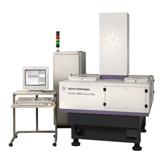
- Page 1 Agilent Technologies 5DX Series 5000 Installation Guide Series 5000 Manual Version A Software Revision 8.0 April 2002 Copyright Agilent Technologies, Inc. All Rights Reserved N7200-90116...
- Page 2 Emergency Shut Down Procedure In the event of a disaster or system emergency, shut down the 5DX by pressing one of the Emergency Stop Buttons, as indicated in Figure T-1: Emergency Stop Button X-ray On Indicator (Locking Switch) Emergency Stop Release Keys Series 5000 Emergency Stop Button locks...
-
Page 3: Notices
INCLUDING, BUT NOT LIMITED TO, THE IMPLIED WARRANTIES OF NONINFRINGEMENT, MERCHANTABILITY AND FITNESS FOR A PARTICULAR PURPOSE. Agilent Technologies shall not be liable for errors contained herein, nor for direct, indirect, general, special, incidental or consequential damages in connection with the furnishing, performance, or use of this material. -
Page 4: Safety Information
Safety Information WARNING This product produces X-rays. Do not attempt to open any part of the product. Exposure to X-rays can cause serious bodily injury. Refer all servicing to service-trained personnel. This product produces X-rays. Do not operate this product or turn on WARNING the X-rays source unless all shielding is in place. - Page 5 SAFETY SYMBOLS WARNING Calls attention to a procedure, practice, or condition that could result in bodily injury or death. Caution Calls attention to a procedure, practice, or condition that could cause damage to equipment or permanent loss of data. Instruction symbol affixed to product. Indicates that the user must refer to the manual for specific WARNING or CAUTION information to avoid personal injury or damage to the product.
- Page 6 POWER and do not use the product until safe operation can be verified by service-trained personnel. If necessary, return the product to an Agilent Technologies Sales and Service Office for service and repair to ensure that safety features are maintained.
-
Page 7: Table Of Contents
Agilent 5DX Installation Guide Emergency Shut Down Procedure ....ii Notices ........iii Safety Information . -
Page 9: Agilent 5Dx Installation
Agilent 5DX Installation Overview This document is intended to guide you through the Agilent 5DX installation process. All major steps have check boxes like this: the left side of the page. Use these check boxes as you proceed with the installation to ensure all steps of the installation are complete. -
Page 10: Time Required For Installation
Time Required for Installation It will generally take one or two days to install the Agilent 5DX System. If this is the first installation at the site, the three-day Basic Maintenance Training should also be provided for the customer’s maintenance personnel and primary operators. -
Page 11: System Arrival, Inspection And Placement
Table 1 Tools/Equipment Required Description Notes Standard CE toolkit with 5DX tool set Agilent PN E7200-67917 Torx Screwdrivers 10, 15, 20, 25 sizes Medium size adjustable wrench Standard (SAE) socket set Multimeter Continuity “beep” is useful Level 25 cm (10 inch) minimum Calipers 6”... - Page 12 This photo shows the 5DX as it is waiting to be shipped from the manufacturing facility. This is how it will look just prior to crating. For shipment, it will have a complete crate around Figure 1 System Arrival The main unit will be on a pallet 165 centimeters wide by 226 centimeters long (87 x 89 inches).
- Page 13 Be careful of cables, hoses, etc., (see the note below about forklift caution.) no more Forklift tines should be than 17.5 centimeters (6.75 inches) wide, set to 87.5 cm (34.5 inch) center-to-center distance apart and be 152 cm (60 inches) long (minimum) (Rear of 5DX shown) Use fork lift here...
- Page 14 — Accessories If there is an accessories crate or pallet, it is advisable to move it to the installation area before opening. (If there is a wooden crate, open it by removing the bolts from the front of each (there are bolts on top as well as on both sides.)) Remove the boxes from the accessory crate or pallet.
- Page 15 Electronics Bay 192 cm (76 in.) high (with status beacon) Height (max.) of main unit is 240 cm (95 in.) Series 5000 Depth (main unit only) 188 cm (74 in.) Width (max.) 146 cm (58 in.) Figure 3 System Dimensions NOTE The main unit while on its pallet is 2.44 meters or 96 inches high.
- Page 16 — Move 5DX To Install Site To remove the 5DX from its pallet, remove the four (15/16”) nuts from the 5DX in the bottom four corners of the main frame. When you are ready, (using acceptable lifting equipment) raise the 5DX from its pallet and move to the install area.
- Page 17 pads with spacers for the estimated height requirement (see Table 3 on page 10). It is recommended that the pads and spacers be put on while the system is elevated by the fork lift. The system can be lowered on to the pads and spacers, however this is extremely difficult to execute.
- Page 18 Table 3 Height Configuration Chart Spacer Combinations Minimum Height in Maximum Height in centimeters (inches) centimeters (inches) 81.0 (31.9) 82.9 (32.6) 82.5 (32.5) 84.4 (33.2) 84.1 (33.1) 86.0 (33.9) 85.7 (33.7) 87.6 (34.5) 87.0 (34.2) 88.9 (35.0) A B B 87.3 (34.4) 89.2 (35.1) 88.6 (34.9)
- Page 19 Use these alignment marks on the 5DX to align the system with the customer’s line. (left side shown) Figure 4 Stage Rail Alignment Markings Agilent 5DX Installation...
- Page 20 Check the height of both stage rail belts. (If the system has a middle rail, you can use only the outer rails “Fixed” Stage Rail for height adjustment.) Adjustable Stage Rail Foot with threaded shaft Height of Stage A spacer Belt (top) Above Floor B spacer...
- Page 21 Recommended Locations ⊗ Air Service ⊕ Electric service Outer Barriers Flexible conduit to allow at least 92 cm (36 in.) movement is ideal. 146 cm 58 in. Main Unit The mobile workstation table would normally be 191 cm positioned here. 75 in.
-
Page 22: System Hardware Installation And Setup
System Hardware Installation and Setup Site preparation and movement to the final location should be complete at this point. Verify correct placement of the main unit, and subsystems (such as the Electronics Bay, user interface and monitor) with your customer (see Figure 6). - Page 23 Remove the inner barrier brackets by removing the three screws (each bracket) securing them to the frame. Screw locations: use a 9/64 hex wrench for the ones on the side and a 5/32 for the top one. Figure 7 Inner Barrier Bracket —...
- Page 24 — Inspect the condition of Electronics Bay Subassemblies & PCBs electronics subassemblies. Inspect the individual subassemblies and pc boards; look for those which may have unseated during shipping. Particular attention should be paid to the motion driver assemblies. — Route the monitor, keyboard and Mobile Workstation Cabling operator console cabling toward the mobile workstation table location.
- Page 25 Electronics Bay (rear view) This drawing is provided for reference. As long as the cable tether is kept in place, the cables should remain installed correctly. (The electronics bay is shown The cable bundle from the main unit without the rear is routed through the larger hole in door.) the bottom panel.
- Page 26 — Unpack and assemble the Mobile Workstation Table Assembly mobile workstation “Computer Table” according to the manufacturer’s instructions included with the unit. Set the height of the keyboard table and monitor shelf according to customer needs. — Unpack the monitor, keyboard, Operator Interface Assemblies and mouse and put them on the workstation table.
- Page 27 to in the Site Preparation Guide) that is provided by local facilities. Do not plug a printer that requires 108-110 volts in to the Caution workstation power supply on the 5DX. This power supply is 200- 208 or 220-240 volts. Damage will occur to the printer. Customers outside the United States and Canada receive printers requiring 220-240 Volts.
- Page 28 Air input assembly Air input Air filter canister - push up in here and turn counterclockwise. Figure 9 Air Input and Filter Canister — Inspect the inside of the Main Cabinet Main Cabinet Inspection • verify that there are no loose items •...
- Page 29 the labels. Be very careful to when making this connection since the pins are very small and fragile. Use great care to orient the sockets correctly! Incorrect connection CAN BE forced. Connector damage will result. If the sockets are incorrectly oriented, there will be no image in the image window.
- Page 30 To Mains E1135C POWER DISTRIBUTION UNIT Supply MAINS 100-240V ~ 1 o 50-60 Hz 200-240V ~ 3 o 200-415V ~ 3 o 80A MAX ___VAC ___ o ___ FLA CB10 Have the electrician secure the conduit with appropriate fittings to the PDU. See the appendix for the PDU for additional information.
- Page 31 The auxiliary outlets are numbered. The following components plug into the respective auxiliary outlets as follows: • Outlet 1 — Rear Laser Displacement Sensor • Outlet 2 — Front Laser Displacement Sensor • Outlet 3 — • Outlet 4 — •...
-
Page 32: System Performance Verification Procedure
System Performance Verification Procedure The following procedures should be closely followed to verify proper system performance.These steps will verify that all levels are correct before full power is applied to all assemblies. — After the site power (main) is connected to the AC Voltage Check PDU, unplug all subassembly AC power cords. - Page 33 Check that the other components in the electronics bay are in the state, so they will power up when the PDU is switched on. Turn on PDU breaker, but not the switch. — The switch should be off on the expansion chassis. CPU Power Up The power for the main CPU (Kayak computer) is controlled by NOTE...
- Page 34 Measure the voltage VACION PUMP POWER SUPPLY here (J04000) INPUT J04000 ~200-240 V 60VA POWER Figure 12 Vacion Power Supply — Enable the X-ray key and press the switch. Check Interlocks Tap each of the 6 side doors, 2 topside access panels, tower door and interlock points with your hand.
-
Page 35: System Start-Up
System Start-up Press Ctrl Alt Del and the login screen Log on to the Computer - will appear. It already has “Administrator” as the user name. Type in the password and press . You will see a dialog box appear like Enter that below;... - Page 36 The system will begin the start-up procedure (see Figure 15). =========================================== PERFORMING AUTOMATIC STARTUP PROCEDURE =========================================== Figure 15 Start-up message - There will be several messages about the system starting up Start-up and initializing subsystems. During this, the system should home the stage and start the rotary scintillator.
- Page 37 Figure 16. Press Esc to exit X-ray Startup, since you don’t want to bring up X-rays yet.Panel Handling should be verified before X-rays are turned on. 5DX X-ray Control COLD Start Agilent Technologies xx minutes remaining Kilovolts (160) MicroAmps (100) Filament (V)
-
Page 38: Panel Handling Subsystem Verification
Panel Handling Subsystem Verification NOTE All main cabinet access panels must be closed and the green and red interlock LEDs lighted on the operator control console. NOTE When installing a Pay Per Use system, remember to use Agilent CE test credits during all panel handling verification, so as not to use customer credits during this setup phase. - Page 39 • Verify that the stage rails align to the production line rails for the load and unload transitions (if this is an in-line installation). Refer to the online Service Guide for troubleshooting. This drawing represents a left to right system. Flow is reversed for a right to left system Board in...
- Page 40 At the prompt, enter (see note below) and press . This Enter 11450 number is the width of the confirmation panel in mils (1 mil equals Ø.ØØ1 inches). NOTE It is recommended you use the value for the newer Confirmation and Adjustment board (E7200-90039) for installation.
- Page 41 • Type to return to the master directory. • Type and press Enter loadinit • Type and press to return to User Interface. Enter auto • Close all access panels. From the menu select Utilities Panel Handling > Home Rails Select .
- Page 42 problem--do not bring up X-Rays. Refer to the online Service Guide (N7200-90041) for troubleshooting. Caution If the reading is not less than 20mv, allow more time for the Vacion power supply to operate. Recheck this again before proceeding. Select System Access then Quit from 5DX.
- Page 43 From the DOS prompt, type and press Enter. Type and edit the line labeled Cold Start vs xray.cfg Rampup so it has a value of (this is the original value). As before, use Alt W to save and Alt X to exit. Type and press Enter to return to the master directory.
- Page 44 Select the camera icon on the graphic display window. Switch the display to Live Laminography. Verify that the 5 dot calibration pattern is visible on the graphic display window. (Some adjustment of the focus (Z axis) may be required.) and press Enter. From the DOS prompt type auto —...
- Page 45 Load the confirmation and adjustment board, if not still in from previous step. From the Utilities menu, select Align Board. When prompted, Manual Use Previous Alignment for all views choose A Caution Box will appear: Board will need to be exposed to continuous X-rays. Do you want to turn on Live X-rays (Y/N) Press Y.
- Page 46 — To verify that system Hardware Reliability Functional Checks hardware is functioning properly, perform the following steps: System Access From the User Interface menu, select menu, select Quit from 5DX. From the DOS prompt type and press Enter. auto -demo NOTE This command will initiate and repeat the automatic inspection mode for the confirmation and adjustment board.
- Page 47 from the Adjust menu and press Enter. Select Backup/Restore and press Enter. Select Backup Adjustments — Request a test panel/board from the Verify a Customer Board customer. If the customer already has 5DX systems in place, check a typical application to be used on this machine. If this is the first 5DX on site, verify that the customer’s board will load and unload.
- Page 48 Save the file and exit from Windows Explorer. You will need to reset the 5DX to allow the changes to be recognized. Before you continue, verify that there is no panel inside the 5DX. Select User Interface > System Access > Shutdown > Long Term Shutdown.
- Page 49 — Mail original X-ray Safety Test Mail All Original Documentation Report (E7200-90084 or N7200-90092) and signed Hardware Acceptance (5021-1982) to: SPT HW Support Manager Agilent Technologies, Inc. 815 14th Street S.W. MS BU221 Loveland, CO 80537-6390 Notes: Agilent 5DX Installation...
- Page 50 Agilent 5DX Installation...
-
Page 51: Appendix A: Smema
Appendix A SMEMA Introduction The communication interface between adjacent machines is provided by way of a Surface Mount Equipment Manufacturers Association (SMEMA) compliant protocol. The purpose of multi-machine in-line interfacing is to allow the Agilent 5DX to integrate directly into your printed circuit assembly manufacturing process. -
Page 52: Smema Signals
SMEMA Signals Table A-1 identifies the SMEMA electrical interface signals that are used by the 5DX. Figure A-2 graphically represents these signals in a process flow diagram. Table A-1 SMEMA electrical interface signals SMEMA Signal Digital I/O Assembly Function Name Description Send Request Input SMEMA SRI - Panel In... - Page 53 Table A-1 SMEMA electrical interface signals SMEMA Signal Digital I/O Assembly Function Name Description Untested Panel Rear SMEMA UPO The 5DX with the middle rail Output (UPO) installed uses this signal to indicate that the panel being sent in the rear lane has not been tested.
- Page 54 NOTE See Table A-1 on page A-44for an explanation of the SMEMA electrical interface signals that are referenced in Figure A-2. Figure A-3 shows the electrical interface schematic for the 5DX, using only the front connectors. The rear connections are a duplicate of the front connections.
-
Page 55: Smema Connectors
SMEMA Connectors Figure A-4 shows a connector with all pin numbers labeled, and Table A-2 shows the pin number and signal description for the 5DX SMEMA connectors., 206043-1 Figure A-4 A typical SMEMA connector with pins numbered Agilent 5DX Installation SMEMA A-47... - Page 56 Table A-2 SMEMA connector information Connector Pin# Signal Description Upstream SMEMA Ready to Accept - 5DX is ready to receive a panel. Floating signal return for (1) Panel Available - Upstream equipment is ready to send a panel. Electrical ground 5-13 Grounded shield Downstream SMEMA...
-
Page 57: Appendix B: Wiring Configuration
Appendix B Wiring Configuration Wiring Configuration This appendix contains the wiring configuration information for the Agilent 5DX System. There are two possible wiring configurations for the 5DX: a three phase wye or delta and a three phase wye with neutral. The drawings in this appendix show how the Power Distribution Unit (PDU) is wired for those configurations. - Page 58 Table B-1 Agilent 5DX Power Source and Loading Configuration Options Power Input Configuration, Description Source Input Wiring, and Terminal Block Wiring Loading 3-Phase Delta 200V Load: L1-L2 200 - 240V 220V L1-L3 Three Phase L2-L3 230V (17 A) Input and Terminal Block Wiring-Figure B-4 240V 3-Phase...
- Page 59 Figure B-2 PDU Outlets 50 Hz 60 Hz 100V 208V 120V 220V 127V 230V 200V 240V Outlet 1 — Laser Displacement Unit 2 Outlet 2 — Laser Displacement Unit 1 Outlet 3 — Outlet 4 — Outlet 5 — X Motor Servo Module Outlet 6 —...
-
Page 60: 3-Phase Wye Or Delta
3-Phase Wye or Delta OPTIONS: 3PD 3PY E4000-61623 Monitor 03066-61635 Expansion Chassis LL1 LL2 NEU G 10A 10A Chassis Ground “MAINS” Figure B-3 Input Wiring — 3-Phase Wye or Delta B-52 Wiring Configuration Agilent 5DX Installation... - Page 61 GRN/YEL Main Cabinet GND GRN/YEL GRN/YEL PDU Outlets BLUE BLUE BLUE BLUE BLUE CB10 GRN/YEL 220Volts AC Switched GRN/YEL Outlets in the Main Cabinet for: GRN/YEL X-ray Tower Fan, VacIon Pump Power Supply and 220Volts AC Switched High Voltage Power Supply Outlets in the Electronics Bay for: Focus Coil Power Supply,...
-
Page 62: 3-Phase Wye With Neutral
3-Phase Wye with Neutral OPTIONS: E4000-61623 Monitor 03066-61635 Expansion Chassis LL1 LL2 NEU G 10A 10A Chassis Ground “MAINS” Figure B-5 Input Wiring — 3-Phase Wye with Neutral B-54 Wiring Configuration Agilent 5DX Installation... - Page 63 GRN/YEL Main Cabinet GND GRN/YEL GRN/YEL PDU Outlets BLUE BLUE CB10 BLUE BLUE 220Volts AC Switched GRN/YEL Outlets in the Main Cabinet for: GRN/YEL X-ray Tower Fan, VacIon Pump Power Supply and 220Volts AC Switched High Voltage Power Supply Outlets in the Electronics Bay for: Focus Coil Power Supply, Low Voltage Power Supply,...
- Page 64 The following table shows the Agilent Country Code and associated power options for most countries of the world. All configurations are three phase. Table B-2 5DX Country Specific Electrical Information Country Agilent Agilent Nominal Nominal Number Country Power Voltage Freq. Code Option Wires*...
- Page 65 Table B-2 5DX Country Specific Electrical Information Country Agilent Agilent Nominal Nominal Number Country Power Voltage Freq. Code Option Wires* Belize Benin 220/380 Bermuda (Dependent Territory of the UK) Bermuda (Dependent 120/208 Territory of the UK) Bolivia Bolivia 230/400 Botswana 230/400 Brazil Brazil...
- Page 66 Table B-2 5DX Country Specific Electrical Information Country Agilent Agilent Nominal Nominal Number Country Power Voltage Freq. Code Option Wires* Cameroon 127/220 Cameroon 230/400 Canada Cape Verde 220/380 Cayman Islands (Dependent Territory of the UK) Central African Republic 220/380 Chad 220/380 Chile 220/380...
- Page 67 Table B-2 5DX Country Specific Electrical Information Country Agilent Agilent Nominal Nominal Number Country Power Voltage Freq. Code Option Wires* Djibouti 220/380 Dominican Republic Ecuador Ecuador 127/220 Egypt 220/380 El Salvador Fiji 240/415 Finland 230/400 France France 127/220 France 220/380 Gabon 220/380 The Gambia...
- Page 68 Table B-2 5DX Country Specific Electrical Information Country Agilent Agilent Nominal Nominal Number Country Power Voltage Freq. Code Option Wires* Grenada 230/400 Guatemala Guinea 220/380 Guinea-Bissau 220/380 Guyana Haiti Honduras Hong Kong 220/380 Hungary 220/380 Iceland 220/380 India 230/400 Indonesia 220/380 Indonesia 127/220...
- Page 69 Table B-2 5DX Country Specific Electrical Information Country Agilent Agilent Nominal Nominal Number Country Power Voltage Freq. Code Option Wires* Jamaica Japan 50 or 60 Jordan 220/380 Kazakhstan 220/380 Kenya 240/415 Korea, Republic of (South Korea) Korea, Republic of (South 220/380 Korea) Kuwait...
- Page 70 Table B-2 5DX Country Specific Electrical Information Country Agilent Agilent Nominal Nominal Number Country Power Voltage Freq. Code Option Wires* Mali 220/380 Malta and Gozo 240/415 Mauritania 220/380 Mauritius 230/400 Mexico 127/220 Monaco 127/220 Monaco 220/380 Morocco 127/220 Morocco 220/380 Mozambique 220/380 Myanmar (Burma)
- Page 71 Table B-2 5DX Country Specific Electrical Information Country Agilent Agilent Nominal Nominal Number Country Power Voltage Freq. Code Option Wires* Nicaragua Niger 220/380 Nigeria 230/400 Norway 220/380 Norway Oman 240/415 Pakistan 230/400 Palau Panama Paraguay 220/380 Peru Peru 220/380 Philippines Philippines 127/220 Poland...
- Page 72 Table B-2 5DX Country Specific Electrical Information Country Agilent Agilent Nominal Nominal Number Country Power Voltage Freq. Code Option Wires* Qatar 240/415 Romania 220/380 Russia 220/380 Rwanda 220/380 Saudi Arabia 127/220 Senegal 127/220 Serbia and Montenegro 220/380 Seychelles 240/415 Sierra Leone 230/400 Singapore 230/400...
- Page 73 Table B-2 5DX Country Specific Electrical Information Country Agilent Agilent Nominal Nominal Number Country Power Voltage Freq. Code Option Wires* Suriname 127/220 Swaziland 230/400 Sweden 230/400 Switzerland 220/380 Syria 220/380 Tahiti, Society and 127/220 Marquesas Islands Taiwan Tajikistan 220/380 Tanzania 230/400 Thailand 220/380...
- Page 74 Table B-2 5DX Country Specific Electrical Information Country Agilent Agilent Nominal Nominal Number Country Power Voltage Freq. Code Option Wires* Uganda 240/415 Ukraine 220/380 United Arab Emirates 230/400 United Kingdom - England 230/415 Scotland Wales N. Ireland United States United States 120/208 Uruguay 220/380...