Table of Contents
Advertisement
Quick Links
Advertisement
Table of Contents

Related Manuals for Agilent Technologies 5975 MSD


Summary of Contents for Agilent Technologies 5975 MSD
- Page 1 Agilent 5975/5977 MSD for OpenLAB CDS Operation Manual Agilent Technologies...
- Page 2 Notices © Agilent Technologies, Inc. 2015 Warranty Safety Notices No part of this manual may be reproduced in The material contained in this docu- any form or by any means (including elec- ment is provided “as is,” and is sub-...
-
Page 3: About This Manual
About This Manual This manual contains information for operating and maintaining the Agilent 5975 through 5977 series of MSD with OpenLAB CDS software. Agilent OpenLAB CDS is a new operating system for Agilent instruments. The Agilent 5977B Series Mass Selective Detector (MSD) is the base instrument described in this manual. -
Page 4: Hardware User Information
Hardware User Information 5977B MSD Accompanying your hardware and software, is a comprehensive collection of manuals, videos, user applications, and method development tools. These are located on the Agilent GC and GC/MS User Manuals and Tools DVD set. See the Agilent 5977B MSD System Quick Start document (G7077-90103) for more details on how to install this information on your computer. -
Page 5: Table Of Contents
Contents About This Manual Hardware User Information 5977B MSD 5975/5977 Series MSD prior to the 5977B MSD Introduction 5977B Series MSD Version Abbreviations Used The 5977B Series MSD MSD Hardware Description Important Safety Warnings Hydrogen Safety GC precautions Precautions Safety and Regulatory Certifications (5977B) Cleaning/Recycling the Product Liquid Spillage Moving or Storing the MSD... - Page 6 To Install a Capillary Column in the GC/MS Interface Using a Standard Column Nut Operating in Electron Ionization (EI) Mode Operating the MSD from the Data System Operating the MSD from the GC control panel Configuring the MSD through the Web User Interface (WUI) To change the network settings of the MSD Operating the 5975/5977 MSD from the local control panel (LCP)
- Page 7 To Pump Down the MS To Move or Store the MSD General Maintenance Before Starting Maintaining the Vacuum System Maintaining the Analyzer To Open the Analyzer Chamber To Remove the EI Ion Source To Disassemble the Standard or Inert EI Ion Source To Disassemble the Extractor EI Ion Source To Clean the EI Ion Source To Assemble a Standard or Inert EI Ion Source...
- Page 8 5975/5977 Series MSD Operation Manual...
- Page 9 Safety and Regulatory Certifications (5977B) Cleaning/Recycling the Product Liquid Spillage Moving or Storing the MSD To Replace the Primary Fuses This chapter describes general information about the MSD, including a hardware description, general safety warnings, and hydrogen safety information. Agilent Technologies...
-
Page 10: Introduction
Introduction 5977B Series MSD Version The 5977B Series MSDs are equipped with a turbomolecular (turbo) pump and a choice of four foreline pumps or a diffusion pump paired with a Pfeiffer DUO 2.5 foreline pump. There are two types of EI sources, a standard stainless steel EI source and an extraction EI source available on the Inert Plus MSD model. -
Page 11: Abbreviations Used
Introduction Abbreviations Used The abbreviations in Table 2 are used in discussing this product. They are collected here for convenience. Table 2 Abbreviations Abbreviation Definition Alternating current Automatic liquid sampler Bromofluorobenzene (calibrant) Chemical ionization Direct current DFTPP Decafluorotriphenylphosphine (calibrant) Direct insertion probe Data System Electron ionization Electron multiplier (detector) - Page 12 Introduction Table 2 Abbreviations (continued) Abbreviation Definition Mass selective detector Negative CI Octafluoronaphthalene (calibrant) Positive CI PFDTD Perfluoro-5,8-dimethyl-3,6,9-trioxydodecane (calibrant) PFHT 2,4,6-tris(perfluoroheptyl)-1,3,5-triazine (calibrant) PFTBA Perfluorotributylamine (calibrant) Quad Quadrupole mass filter Radio frequency RFPA Radio frequency power amplifier Torr Unit of pressure, 1 mm Hg Turbo Turbomolecular (pump) 5975/5977 Series MSD Operation Manual...
-
Page 13: The 5977B Series Msd
Introduction The 5977B Series MSD The 5977B Series MSD is a stand-alone capillary GC detector for use with either an Agilent 7890B Series or an Agilent 7820 Gas Chromatograph. The MSD features: • WEB User Interface (WUI) for locally monitoring and operating the MSD •... - Page 14 Introduction Vacuum gauge The MSD may be equipped (or ordered) with an ion vacuum gauge. The OpenLAB CDS Acquisition software can be used to read the pressure (high vacuum) in the vacuum manifold. Operation of the gauge controller is described in this manual. Table 3 5977B Series MSD features Feature...
-
Page 15: Msd Hardware Description
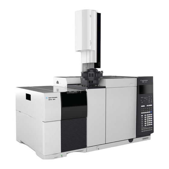
Introduction MSD Hardware Description Local control panel 7890B GC 5977B Series MSD power switch Front panel LED GC power switch Figure 1 5977B Series GC/MSD system, shown with Agilent 7890B GC 5975/5977 Series MSD Operation Manual... -
Page 16: Important Safety Warnings
Introduction Important Safety Warnings There are several important safety notices to always keep in mind when using the MSD. Many internal parts of the MSD carry dangerous voltages If the MSD is connected to a power source, even if the power switch is off, potentially dangerous voltages exist on: •... - Page 17 Introduction Many parts are dangerously hot Many parts of the GC/MSD operate at temperatures high enough to cause serious burns. These parts include but are not limited to: • The GC inlets • The GC oven and its contents including the column nuts attaching the column to a GC inlet, GC/MS interface, or GC detector •...
-
Page 18: Hydrogen Safety
Introduction Hydrogen Safety Using hydrogen as a GC carrier gas is potentially dangerous. WARNING When using hydrogen (H ) as the carrier gas or fuel gas, be aware that hydrogen WARNING can flow into the GC oven and create an explosion hazard. Therefore, be sure that the supply is turned off until all connections are made and ensure that the inlet and detector column fittings are either connected to a column or capped at all times when hydrogen is supplied to the instrument. - Page 19 Introduction Dangers unique to GC/MSD operation Hydrogen presents a number of dangers. Some are general, others are unique to GC or GC/MSD operation. Dangers include, but are not limited to: • Combustion of leaking hydrogen • Combustion due to rapid expansion of hydrogen from a high-pressure cylinder •...
-
Page 20: Precautions
Introduction Table 4 Hydrogen accumulation mechanisms (continued) Mechanism Results Mass spectrometer manual shutoff Some mass spectrometers are equipped with manual valves closed diffusion pump shutoff valves. In these instruments, the operator can close the shutoff valves. Closing the shutoff valves does not shut off the flow of carrier gas. As a result, hydrogen may slowly accumulate in the mass spectrometer. - Page 21 Introduction Equipment precaution You MUST make sure the front side-plate thumbscrew is fastened finger-tight. Do not overtighten the thumbscrew; it can cause air leaks. Failure to secure your MSD as described above greatly increases the chance of WARNING personal injury in the event of an explosion. You must remove the plastic cover over the glass window on the front of a 5977B Series MSD.
- Page 22 Introduction 4 Eliminate all potential sources of ignition in the room. 5 Open the vacuum manifold of the MSD to atmosphere. 6 Wait at least 10 minutes to allow any hydrogen to dissipate. 7 Start up the GC and MSD as normal. When using hydrogencheck the system for leaks to prevent possible fire and explosion hazards based on local Environmental Health and Safety (EHS) requirements.
-
Page 23: Safety And Regulatory Certifications (5977B)
ISO 9001. The 5977B Series MSD is RoHS compliant. Information The Agilent Technologies 5977B Series MSD meets the following IEC (International Electro-technical Commission) classifications: Equipment Class I, Laboratory Equipment, Installation Category II, Pollution Degree 2. This unit has been designed and tested in accordance with recognized safety standards and is designed for use indoors. - Page 24 Failure to comply with these precautions violates safety standards of design and the intended use of the instrument. Agilent Technologies assumes no liability for the customer’s failure to comply with these requirements.
- Page 25 Ensure that all peripheral devices are also certified. Ensure that appropriate cables are used to connect the device to peripheral equipment. Consult your equipment dealer, Agilent Technologies, or an experienced technician for assistance. Changes or modifications not expressly approved by Agilent Technologies could void the user’s authority to operate the equipment.
-
Page 26: Cleaning/Recycling The Product
Introduction Cleaning/Recycling the Product To clean the unit, disconnect the power and wipe down with a damp, lint-free cloth. For recycling, contact your local Agilent sales office. Liquid Spillage Do not spill liquids on the MSD. Moving or Storing the MSD The best way to keep your MSD functioning properly is to keep it pumped down and hot, with carrier gas flow. -
Page 27: To Replace The Primary Fuses
Introduction To Replace the Primary Fuses Materials needed • Fuse, T12.5A, 250 V (2110-1398) – 2 required • Screwdriver, flat-blade (8730-0002) The most likely cause of failure of the primary fuses is a problem with the foreline pump. If the primary fuses in your MSD fail, check the foreline pump. Procedure Vent the MSD and unplug the power cord from the electrical outlet. - Page 28 Introduction Primary fuses in holders Figure 2 Primary fuses Repeat steps through for the other fuse. Always replace both fuses. Reconnect the MSD power cord to the electrical outlet. Pump down the MSD. 5975/5977 Series MSD Operation Manual...
-
Page 29: Installing Gc Columns
Before you can operate your GC/MSD system, you must select, install, and condition a GC column. This chapter shows you how to install and condition a column. For correct column and flow selection, you must know what type of vacuum system your MSD has. Agilent Technologies... -
Page 30: Columns
Installing GC Columns Columns Many types of GC columns can be used with the MSD but there are some restrictions. During tuning or data acquisition, the rate of column flow into the MSD should not exceed the maximum recommended flow. Therefore, there are limits to column length, diameter, and flow. - Page 31 Installing GC Columns Conditioning columns Conditioning a column before it is connected to the GC/MSD interface is essential. See “To Condition a Capillary Column” on page 36. A small portion of the capillary column stationary phase is often carried away by the carrier gas.
- Page 32 Installing GC Columns Always wear safety glasses when handling capillary columns. Use care to avoid WARNING puncturing your skin with the end of the column. 5977B Series MSD Operation Manual...
-
Page 33: To Install A Capillary Column In A Split/Splitless Inlet
Installing GC Columns To Install a Capillary Column in a Split/Splitless Inlet Materials needed • Gloves, clean • Large (8650-0030) • Small (8650-0029) • Metric ruler • Wrench, open-end, 1/4-inch and 5/16-inch (8710-0510) • Capillary column • Column cutter, ceramic (5181-8836) or diamond (5183-4620) •... - Page 34 Installing GC Columns Always wear clean gloves while handling any parts that go inside the GC or analyzer CA UT IO N chambers. Procedure 1 Cool the oven and inlet to room temperature. 2 Wearing clean gloves, press the column through the septum (this takes a bit of pressure).
- Page 35 Installing GC Columns 7 Position the column so it extends 4 to 6 mm past the end of the ferrule (Figure Insulation cup Reducing nut Capillary column 4 to 6 mm Ferrule (inside nut) Inlet column nut Septum Figure 4 Installing a capillary column for a split/splitless inlet 8 Slide the septum up to the bottom of the nut to fix the correct column insertion length.
-
Page 36: To Condition A Capillary Column
Installing GC Columns To Condition a Capillary Column Materials needed • Carrier gas, (99.9995% pure or better) • Wrench, open-end, 1/4-inch and 5/16-inch (8710-0510) Do not condition your capillary column with hydrogen. Hydrogen accumulation in WARNING the GC oven can result in an explosion. If you plan to use hydrogen as your carrier gas, first condition the column with ultrapure (99.999% or better) inert gas such as helium, nitrogen, or argon. -
Page 37: To Install A Capillary Column In The Gc/Ms Interface Using The Self-Tightening Column Nut
Installing GC Columns To Install a Capillary Column in the GC/MS Interface Using the Self-Tightening Column Nut This procedure is for the installation of a capillary column directly into the analyzer using the Agilent recommended self-tightening column nut. Materials needed ... - Page 38 Installing GC Columns Procedure 1 Condition the column. (See “To Condition a Capillary Column” on page 36.) The analyzer, GC/MS interface, and other components in the analyzer chamber WARNING operate at very high temperatures. Do not touch any part until you are sure it is cool. Dangerous voltages exist inside the analyzer chamber, which can result in fatal WARNING injury.
- Page 39 Installing GC Columns 8 Slide the column into the GC/MS interface. For an EI Source Installation (Figure 5), the column extends 1 to 3 mm. Use the flashlight and magnifying loupe, if necessary, to see the end of the column inside the analyzer chamber.
- Page 40 Installing GC Columns Figure 6 Installing a capillary column in the GC/MS interface Use care when placing the isolation tip on the end of the GC/MS interface to avoid CA UT IO N damaging the column. 12 Install the isolation tip on end of the GC/MS interface. For the CI GC/MS interface and the EI GCMS interface with an extractor EI source (Figure install the tip seal spring, then align and gently slide the tip with knurled...
-
Page 41: Gcms Transfer Line Tip Seals
Installing GC Columns 13 Gently check the alignment of the ion source and the interface tip seal. When the ion source is aligned correctly, the front analyzer chamber can be closed all the way with no resistance except the spring tension from the interface tip seal. -
Page 42: To Install A Capillary Column In The Gc/Ms Interface Using A Standard Column Nut
Installing GC Columns To Install a Capillary Column in the GC/MS Interface Using a Standard Column Nut This procedure is for the installation of a capillary column directly into the analyzer. There are two types of column nuts that can be used in the GC/MS interface: The standard column nut explained here, and the self tightening column nut explained in the next section. - Page 43 Installing GC Columns Procedure Always wear clean gloves while handling any parts that go inside the GC or the CA UT IO N analyzer chambers. The analyzer, GC/MS interface, and other components in the analyzer chamber WARNING operate at very high temperatures. Do not touch any part until you are sure it is cool. 1 Condition the column.
- Page 44 Installing GC Columns 10 Tighten the nut 1/4 to 1/2 turn. 11 Check the nut’s tightness after one or two heat cycles; tighten additionally as appropriate. Use care when placing the isolation tip on the end of the GC/MS interface to avoid CA UT IO N damaging the column.
- Page 45 To Open the MSD Covers Vent the MSD To Pump Down the MS To Move or Store the MSD This chapter describes how to perform some basic operating procedures for the Agilent 5975/5977 series GC/MSD using electron ionization. Agilent Technologies...
-
Page 46: Operating In Electron Ionization (Ei) Mode
Operating in Electron Ionization (EI) Mode Operating the MSD from the Data System The Agilent OpenLAB CDS software automates tasks such as pumping down, monitoring settings, setting temperatures, tuning, and venting the MSD. These tasks are described in this chapter. Additional information is described in the manuals and online help supplied with the OpenLAB CDS software. -
Page 47: Operating The Msd From The Gc Control Panel
Operating in Electron Ionization (EI) Mode Operating the MSD from the GC control panel This section only applies to the 5977B MSD. For earlier 5975/5977 MSD models, refer to “Operating the 5975/5977 MSD from the local control panel (LCP)”on page 54. The 7890B GC control panel can show the actual temperature and pressure of the MSD or initiate a task on the MSD without using the Agilent OpenLAB CDS software. - Page 48 Operating in Electron Ionization (EI) Mode Press Enter to apply the changes. To view MSD vacuum pressure and Turbo speed/Foreline Pressure from the GC control panel Press MS/Aux Det to display the 5977B MSD menu. Press the down arrow to scroll to HiVac Pressure, or Turbo Speed % of full Foreline Pressure.
- Page 49 Operating in Electron Ionization (EI) Mode To configure the network settings for the MSD from the GC control panel Press Config, and then press MS/Aux Det to bring up the CONFIGURE MS DETECTOR menu. To configure the IP: parameter, use the GC keypad to enter the new IP address for the MSD, then press Enter to complete the entry.
- Page 50 Operating in Electron Ionization (EI) Mode To enable/disable LVDS on MSD Press Config, and then press MS/Aux Det to bring up the CONFIGURE MS DETECTOR menu. Press the down arrow to scroll to Lvds communication. If you want to enable the LVDS, press On/Yes. If you want to disable the LVDS, press Off/No.
-
Page 51: Configuring The Msd Through The Web User Interface (Wui)
Operating in Electron Ionization (EI) Mode Configuring the MSD through the Web User Interface (WUI) If your MSD does not support LVDS communications with an Agilent GC you can use the WUI to configure the MSD network settings. Reasons that a GC does not support configuring a 5977B MSD’s network settings from the GC control panel include any of the following: •... - Page 52 Operating in Electron Ionization (EI) Mode Copy down the IP address, gateway, and subnet mask from the mini display readout. 4 Enter the IP address into a PC web browser URL to display the web user interface (WUI) page shown here. Figure 7 WEB User Interface 5 Click Set Real-Time Clock or Edit NetConfig and go to Edit NetConfig (MSD network...
- Page 53 Operating in Electron Ionization (EI) Mode Figure 8 WUI Edit NetConfig Confirm that BootP is set to OFF. If your LAN assigns IP addresses using a BootP server click ON and skip the next step. To update the MSD IP address, Gateway IPA, and SubNet Mask enter the new values.
-
Page 54: Operating The 5975/5977 Msd From The Local Control Panel (Lcp)
Operating in Electron Ionization (EI) Mode Operating the 5975/5977 MSD from the local control panel (LCP) Agilent 5975 and 5977 MSD models introduced before the 5977B MSD have a local control panel (LCP). The LCP shows the status of the MSD or initiates a task on the MSD without using the data acquisition software. - Page 55 Operating in Electron Ionization (EI) Mode Use [Yes/Select] to accept the current value. Use [No/Cancel] to return to the Status mode. After you make your selection, or if you cycle through all available menus, the display automatically returns to Status mode. Pressing [Menu], then [No/Cancel], will always display the Status mode.
- Page 56 Operating in Electron Ionization (EI) Mode LCP Status Messages The following messages may be displayed on the LCP to inform you of the status of the MSD system. If the LCP is currently in Menu mode, cycle through the menus to return to Status mode. No messages will be displayed if data acquisition software is not controlling the MSD.
-
Page 57: To View System Status During Startup
Operating in Electron Ionization (EI) Mode <method> Complete <timestamp> The run and subsequent data processing are done. The same message appears even if the run was terminated prematurely. Method Loaded <method name> Method parameters were sent to the MSD. MS locked by <computer name> MS parameters can only be changed from the Agilent OpenLAB CDS software. - Page 58 Operating in Electron Ionization (EI) Mode Many menu items, especially on the ChemStation, MS Parameters, and Maintenance NO T E menus, have no effect when the instrument is acquiring data. Table 8 ChemStation menu Action Description Run Method Displays the current method name and starts an analysis. Run Sequence Displays the current sequence and starts a sequence.
- Page 59 Operating in Electron Ionization (EI) Mode Table 10 MS Parameters menu (continued) Action Description Turbo Pump Speed Displays the turbo pump speed. Foreline Pressure Displays the foreline pressure. MSD Fault Status Reports a summary fault status code (number) in ‘dec’ (decimal) and ‘hex’...
- Page 60 Operating in Electron Ionization (EI) Mode Table 12 Version menu (continued) Action Description OpenLAB CDS Operating system Displays the operating system version. Front panel Displays the version of the LCP. Log amplifier Displays version information. Sideboard Displays the sideboard type. Mainboard Displays the mainboard type.
-
Page 61: Emodule Mini Display Readout
Operating in Electron Ionization (EI) Mode eModule mini display readout This section only applies to the 5977B MSD. Earlier 5975/5977 MSD models do not have this feature. The eModule mini display, accessible when the analyzer door cover is open, allows the operator to view the LAN configuration of the instrument including its IP address, subnet mask, default gateway, and MAC address. -
Page 62: The Gc/Msd Interface
Operating in Electron Ionization (EI) Mode The GC/MSD Interface The GC/MSD interface (Figure 9 on page 63) is a heated conduit into the MSD for the capillary column. It is bolted onto the right side of the analyzer chamber, with an O-ring seal. It has a protective cover which should be left in place. - Page 63 Operating in Electron Ionization (EI) Mode Ionization Column chamber GC oven Analyzer chamber Heater sleeve Insulation Heater/Sensor assembly Column end protrudes 1 to 2 mm into the ionization chamber. Figure 9 The GC/MSD interface 5975/5977 Series MSD Operation Manual...
-
Page 64: Before You Turn On The Msd
Operating in Electron Ionization (EI) Mode Before You Turn On the MSD Verify the following before you turn on or attempt to operate the MSD. • The vent valve must be closed (the knob turned all the way clockwise). • All other vacuum seals and fittings must be in place and fastened correctly. The front side plate screw should not be tightened, unless hazardous carrier or reagent gases are being used. -
Page 65: Pumping Down
Operating in Electron Ionization (EI) Mode Pumping Down The data system helps you pump down the MSD. The process is mostly automated. Once you close the vent valve and turn on the main power switch (while pressing on the sideplate), the MSD pumps down by itself. The data system software monitors and displays system status during pumpdown. -
Page 66: Venting The Msd
Operating in Electron Ionization (EI) Mode The MSD can be used to measure actual column flow. You inject a small amount of air or other unretained chemical and time how long it takes to reach the MSD. With this time measurement, you can calculate the column flow. -
Page 67: Set Ms Analyzer Temperatures
Operating in Electron Ionization (EI) Mode Set MS Analyzer Temperatures Setpoints for the MSD ion source and mass filter (quad) temperatures are stored in the current tune (*.u) file. When a method is loaded, the setpoints in the tune file associated with that method are downloaded automatically. Enable Tune Control and click Manual Tune >... - Page 68 Operating in Electron Ionization (EI) Mode Release Tune Control. 5975/5977 Series MSD Operation Manual...
-
Page 69: Enable The Gc/Ms Interface And Oven
Operating in Electron Ionization (EI) Mode Enable the GC/MS Interface and Oven Procedure Click Method > Instrument Setup > GC > Aux Heaters. Select On for Thermal Aux 2. Click Oven and select On. Click Download Method to enable these temperature zones in the GC. Save the method. -
Page 70: View Msd Temperatures And Vacuum
Operating in Electron Ionization (EI) Mode View MSD Temperatures and Vacuum Pressure monitoring requires an optional Micro-Ion vacuum gauge (G3397A for the 5975 and G3397B for the 5977).. If you are using hydrogen as a carrier gas, do not turn on the Micro-Ion vacuum WARNING gauge if there is any possibility that hydrogen has accumulated in the analyzer chamber. - Page 71 Operating in Electron Ionization (EI) Mode The largest influence on operating pressure in EI mode is the carrier gas (column) flow. Table 15 lists typical pressures for various helium carrier gas flows. These pressures are approximate and will vary from instrument to instrument by as much as 30%.
-
Page 72: To Calibrate Column Flow Linear Velocity
Operating in Electron Ionization (EI) Mode To Calibrate Column Flow Linear Velocity Capillary columns must be calibrated prior to use with the MS. Procedure Set Data Acquisition for splitless manual injection and set up a real time plot to monitor m/z 28. Press [Prep Run] on the GC keypad. - Page 73 Operating in Electron Ionization (EI) Mode Verify that the parameters listed (temperature, inlet and outlet pressures, and gas type) are those used in the method to determine the holdup time. Change any parameters that are different than those used in your method. 10 Enter the recorded retention time in the Holdup Time field.
-
Page 74: To Run An Autotune
Operating in Electron Ionization (EI) Mode To Run an Autotune A full autotune run takes about 15 to 20 minutes. When the Quick Tune option is not selected, the autotune requires less than five minutes. Alternatively, you can run an autotune from the dashboard. Procedure Enable Tune Control and select Tune >... - Page 75 Operating in Electron Ionization (EI) Mode Release Tune Control. As needed, generate an Evaluate Tune Report. 5975/5977 Series MSD Operation Manual...
-
Page 76: To Open The Msd Covers
Operating in Electron Ionization (EI) Mode To Open the MSD Covers If you need to open one of the MSD covers, follow these procedures. To remove the analyzer window cover Press down on the rounded area on the top of the window, tilt the window slightly forward and lift off the MSD. -
Page 77: Vent The Msd
Operating in Electron Ionization (EI) Mode Vent the MSD Procedure Select Method > MSD > Maintenance > Vent/Pump Down and click Vent to begin the process. Follow the instructions presented. 5975/5977 Series MSD Operation Manual... - Page 78 Operating in Electron Ionization (EI) Mode When prompted, turn the vent valve knob counterclockwise only 3/4 turns or until you hear the hissing sound of air flowing into the analyzer chamber. If you are using hydrogen as a carrier gas, the carrier gas flow must be off before WARNING turning off the MSD power.
-
Page 79: To Pump Down The Ms
Operating in Electron Ionization (EI) Mode To Pump Down the MS You can also use the 7890B GC control panel to perform this task. See “Operating the MSD from the GC control panel”on page 47. Make sure your MSD meets all the conditions listed in the introduction to this WARNING chapter (page... - Page 80 Operating in Electron Ionization (EI) Mode Press lightly on the metal box of the analyzer quad driver board to ensure a correct seal. Start the OpenLAB Data Acquisition program. If the MS was configured for multiple ion source types, you are prompted for the ion source type that is currently installed.
- Page 81 Operating in Electron Ionization (EI) Mode 10 You are prompted to turn on the transfer line heater and the GC oven. Click OK when you have done so. 11 The software will turn on the ion source and mass filter (quad) heaters. The temperature setpoints are stored in the current autotune file.
-
Page 82: To Move Or Store The Msd
Operating in Electron Ionization (EI) Mode To Move or Store the MSD Materials needed • Ferrule, blank (5181-3308) • Interface column nut (05988-20066) • Wrench, open-end, 1/4-inch × 5/16-inch (8710-0510) Procedure Vent the MSD (See “Vent the MSD”on page 77). Remove the column and install a blank ferrule and interface nut. - Page 83 The MSD must remain upright at all times. If you need to ship your MSD to another CA UT IO N location, contact your Agilent Technologies service representative for advice about packing and shipping. 5975/5977 Series MSD Operation Manual...
- Page 84 Operating in Electron Ionization (EI) Mode 5975/5977 Series MSD Operation Manual...
-
Page 85: General Maintenance
To Assemble the Extractor EI Ion Source To Replace a Filament in an EI Ion Source To Install the EI Ion Source To Attach Wiring from the Ion Source to the feedthrough board To Replace the Electron Multiplier Horn To Close the Analyzer Chamber Agilent Technologies... -
Page 86: Before Starting
General Maintenance Before Starting You can perform much of the maintenance required by your MSD. For your safety, read all of the information in this introduction before performing any maintenance tasks. Table 16 Maintenance schedule Task Every week Every 6 months Every year As needed Tune the MSD... - Page 87 General Maintenance Keep a record of system performance (tune reports) and maintenance operations performed. This makes it easier to identify variations from normal operation and to take corrective action. Tools, spare parts, and supplies Some of the required tools, spare parts, and supplies are included in the GC shipping kit, MSD shipping kit, or MSD tool kit.
- Page 88 General Maintenance Some procedures in this chapter require access to the inside of the MSD while the power switch is on. Do not remove any of the electronics safety covers in any of these procedures. To reduce the risk of electric shock, follow the procedures carefully.
- Page 89 General Maintenance Chemical residue Only a small portion of your sample is ionized by the ion source. The majority of any sample passes through the ion source without being ionized. It is pumped away by the vacuum system. As a result, the exhaust from the foreline pump will contain traces of the carrier gas and your samples.
- Page 90 General Maintenance Electrostatic discharge All of the printed circuit boards in the MSD contain components that can be damaged by electrostatic discharge (ESD). Do not handle or touch these boards unless absolutely necessary. In addition, wires, contacts, and cables can conduct ESD to the electronics boards to which they are connected. This is especially true of the mass filter (quadrupole) contact wires which can carry ESD to sensitive components on the side board.
-
Page 91: Maintaining The Vacuum System
General Maintenance Maintaining the Vacuum System Periodic maintenance As listed earlier in Table 16 on page 86, some maintenance tasks for the vacuum system must be performed periodically. These include: • Checking the foreline pump fluid (every week) • Checking the calibration vial(s) (every 6 months) •... -
Page 92: Maintaining The Analyzer
General Maintenance Maintaining the Analyzer Scheduling None of the analyzer components require periodic maintenance. Some tasks, however, must be performed when MSD behavior indicates they are necessary. These tasks include: • Cleaning the ion source • Replacing filaments • Replacing the electron multiplier horn The Agilent 5977B Series MSD Troubleshooting and Maintenance Manual provides information about symptoms that indicate the need for analyzer maintenance. - Page 93 General Maintenance Some parts can be damaged by electrostatic discharge The wires, contacts, and cables connected to the analyzer components can carry electrostatic discharges (ESD) to the electronics boards to which they are connected. This is especially true of the mass filter (quadrupole) contact wires which can conduct ESD to sensitive components on the side board.
-
Page 94: To Open The Analyzer Chamber
General Maintenance To Open the Analyzer Chamber The analyzer chamber should only be opened to clean or replace the ion source, change the detector’s EM, or to change a filament. Materials needed • Gloves, clean, lint-free • Large (8650-0030) •... - Page 95 General Maintenance The bottom thumbscrew on the front analyzer side plate should be unfastened during normal use. It is only fastened during shipping. The top thumbscrew on the front side plate should only be fastened if hydrogen or other flammable or toxic substances are used for carrier gas. In the next step, if you feel resistance, stop.
-
Page 96: To Remove The Ei Ion Source
General Maintenance To Remove the EI Ion Source Materials needed • Gloves, clean, lint-free • Large (8650-0030) • Small (8650-0029) • Pliers, long-nose (8710-1094) Procedure Vent the MSD. See “Vent the MSD” on page 77. The analyzers, GC/MS interface, and other components in the analyzer chamber WARNING operate at very high temperatures. - Page 97 General Maintenance Table 17 Standard and inert EI ion source wires Wire color Connects to Number of leads Blue Entrance lens Orange Ion focus White Filament 1 (top filament) Repeller Black Filament 2 (bottom filament) Ion source Feedthrough board Thumbscrews Source heater and temperature sensor wires Source radiator...
- Page 98 General Maintenance Table 18 Extractor EI (inert+) ion source wires Wire color Connects to Number of leads Blue Entrance lens Orange Ion focus White Filament 1 (top filament) Repeller Black Filament 2 (bottom filament) Brown Extractor lens Ion source Feedthrough board Thumbscrews Extractor wire Source heater and...
-
Page 99: To Disassemble The Standard Or Inert Ei Ion Source
General Maintenance To Disassemble the Standard or Inert EI Ion Source Materials needed • Gloves, clean, lint-free • Large (8650-0030) • Small (8650-0029) • Hex ball driver, 1.5 mm (8710-1570) • Hex ball driver, 2.0 mm (8710-1804) • Wrench, open-end, 10 mm (8710-2353) Procedure Remove the ion source. - Page 100 General Maintenance Figure 13 Disassembling the standard or inert EI ion source Table 19 Parts list for the standard or inert EI ion source (Figure Item number Item description Part number (SSL) Part number (Inert) Gold plated set screw G1999-20022 G1999-20022 Gold plated screw G3870-20021...
- Page 101 General Maintenance Table 19 Parts list for the standard or inert EI ion source (Figure 16) (continued) Item number Item description Part number (SSL) Part number (Inert) Spring washer and flat washer 3050-1374 and 3050-0982 3050-1374 and 3050-0982 Lens insulator G3170-20530 G3170-20530 Entrance lens...
-
Page 102: To Disassemble The Extractor Ei Ion Source
General Maintenance To Disassemble the Extractor EI Ion Source Materials needed • Gloves, clean, lint-free • Large (8650-0030) • Small (8650-0029) • Hex ball driver, 1.5 mm (8710-1570) • Hex ball driver, 2.0 mm (8710-1804) • Wrench, open-end, 10 mm (8710-2353) Procedure Remove the ion source. - Page 103 General Maintenance Figure 14 Disassembling the extractor EI ion source Table 20 Parts list for the extractor EI ion source (Figure Item number Item description Part number Setscrews G3870-20446 Screws G3870-20021 Source body G3870-20440 Extractor lens G3870-20444 Extractor lens insulator G3870-20445 Filaments G7005-60061...
- Page 104 General Maintenance Table 20 Parts list for the extractor EI ion source (Figure 17) (continued) Item number Item description Part number Spring washer and flat washer 3050-1301and 3050-0982 Lens insulator G3870-20530 Entrance lens G3170-20126 Ion focus lens 05971-20143 Repeller insulator G3870-20133 Repeller G3870-60171...
-
Page 105: To Clean The Ei Ion Source
General Maintenance To Clean the EI Ion Source Materials needed • Abrasive paper (5061-5896) • Alumina abrasive powder (8660-0791) • Aluminum foil, clean • Cloths, clean (05980-60051) • Cotton swabs (5080-5400) • Glass beakers, 500 mL • Gloves, clean, lint-free •... - Page 106 General Maintenance Collect the following parts to be cleaned for an extractor EI ion source: (See Figure 15 on page 107.) • Repeller • Insulator • Source body • Extractor lens • Ion focus lens • Entrance lens These are the parts that contact the sample or ion beam. The other parts normally should not require cleaning.
- Page 107 General Maintenance Standard or inert EI ion source parts to be cleaned Source body Ion focus lens Entrance lens Drawout Drawout plate Interface socket cylinder Extractor EI ion source parts to be cleaned Insulator Extractor lens Repeller Entrance Source body Ion focus lens lens Figure 15...
- Page 108 General Maintenance Procedure The filaments, source heater assembly, and insulators cannot be cleaned CA UT IO N ultrasonically. Replace these components if major contamination occurs. If the contamination is serious, such as an oil backflow into the analyzer, seriously consider replacing the contaminated parts. Abrasively clean the surfaces that contact the sample or ion beam.
- Page 109 General Maintenance Let the parts cool before you handle them. WARNING Take care to avoid recontaminating cleaned and dried parts. Put on new, clean gloves NO T E before handling the parts. Do not set the cleaned parts on a dirty surface. Set them only on clean, lint-free cloths.
-
Page 110: To Assemble A Standard Or Inert Ei Ion Source
General Maintenance To Assemble a Standard or Inert EI Ion Source Materials needed • Gloves, clean, lint-free • Large (8650-0030) • Small (8650-0029) • Hex ball driver, 1.5 mm (8710-1570) • Hex ball driver, 2.0 mm (8710-1804) • Wrench, open-end, 10 mm (8710-2353) Procedure ... - Page 111 General Maintenance Do not overtighten the interface socket. Overtightening could strip the threads. CA UT IO N Figure 16 Assembling the standard or inert EI ion source Table 21 Parts list for the standard or inert EI ion source (Figure Item number Item description Part number (SSL)
- Page 112 General Maintenance Table 21 Parts list for the standard or inert EI ion source (Figure 16) (continued) Item number Item description Part number (SSL) Part number (Inert) Source body G1099-20130 G2589-20043 Drawout cylinder G1072-20008 G1072-20008 Drawout plate 05971-20134 G2589-20100 4-turn filament G7005-60061 G7005-60061 Spring washer and flat washer...
-
Page 113: To Assemble The Extractor Ei Ion Source
General Maintenance To Assemble the Extractor EI Ion Source Materials needed • Gloves, clean, lint-free • Large (8650-0030) • Small (8650-0029) • Hex ball driver, 1.5 mm (8710-1570) • Hex ball driver, 2.0 mm (8710-1804) • Wrench, open-end, 10 mm (8710-2353) Procedure Slide the ceramic washer into the source body. - Page 114 General Maintenance Attach the repeller assembly to the source body using the two gold plated screws and spring washers. Install the filaments using the two gold plated screws and spring washers. Figure 17 Assembling the extractor EI ion source Table 22 Parts list for the extractor EI ion source (Figure Item number...
- Page 115 General Maintenance Table 22 Parts list for the extractor EI ion source (Figure 17) (continued) Item number Item description Part number Extractor lens G3870-20444 Extractor lens insulator G3870-20445 Filaments G7005-60061 Spring washer and flat washer 3050-1301and 3050-0982 Lens insulator G3870-20530 Entrance lens G3170-20126 Ion focus lens...
-
Page 116: To Replace A Filament In An Ei Ion Source
General Maintenance To Replace a Filament in an EI Ion Source Materials needed • Filament assembly (G7005-60061) • Gloves, clean, lint-free • Large (8650-0030) • Small (8650-0029) • Hex ball driver, 1.5-mm (8710-1570) Procedure Vent the MSD. See “Venting the MSD” on page 66. - Page 117 General Maintenance Gold plated screws and washers Figure 18 Changing the filament - standard source shown, Extractor source similar Secure the new filament(s) with the gold plated screw and washer. After installing the filament, verify that it is not grounded to the source body. Install the ion source.
-
Page 118: To Install The Ei Ion Source
General Maintenance To Install the EI Ion Source Materials needed • Gloves, clean, lint-free • Large (8650-0030) • Small (8650-0029) • Pliers, long-nose (8710-1094) Procedure Slide the ion source into the source radiator. Ion source Source feedthrough board Thumbscrews Source heater and temperature sensor wires Source radiator... -
Page 119: To Attach Wiring From The Ion Source To The Feedthrough Board
General Maintenance To Attach Wiring from the Ion Source to the feedthrough board Materials needed • Gloves, clean, lint-free • Large (8650-0030) • Small (8650-0029) • Pliers, long-nose (8710-1094) Procedure Attach the internal front analyzer electrical leads to the pins specified in Table 23 on page 119. - Page 120 General Maintenance Blue wire to entrance lens Orange wire to ion focus lens White wires to filament 1 Red wire to repeller Black wires to Brown extractor filament 2 wire to extractor lens Ion source heater Ion source sensor wires (white) wires (white) Figure 20 Feedthrough board wiring...
- Page 121 General Maintenance Entrance lens Filament 1 FB = Feedthrough Board (blue wire from FB) (white wires from FB) Ion source Repeller heater wires (red wire from FB) Ion focus lens (orange wire from FB) Extractor lens (brown wire Ion source from FB) sensor wires connector pin...
-
Page 122: To Replace The Electron Multiplier Horn
General Maintenance To Replace the Electron Multiplier Horn The replacement EM horn part number for this Series 2 detector is stamped on the front face of the detector.Through OpenLAB CDS, you can determine which series detector you have without having to directly check the detector. The detector series is displayed as “Triple Axis Series 2”... - Page 123 General Maintenance Slide the signal wire from the connector in the sideplate. Hold the new horn with the signal wire end down, and attach the signal wire to the connector in the sideplate. Slide the electron multiplier horn into position. Close the retaining clip.
- Page 124 General Maintenance Series 2 Series 1 Figure 23 Electron multiplier horns 5975/5977 Series MSD Operation Manual...
-
Page 125: To Close The Analyzer Chamber
General Maintenance To Close the Analyzer Chamber Procedure Ensure all the internal analyzer electrical leads are correctly attached. Wiring is not the same for both the EI and CI ion sources. The wiring is described in “To Attach Wiring from the Ion Source to the feedthrough board”... - Page 126 General Maintenance Once the MS has pumped down, close the left analyzer cover and replace the window cover. Tune the MS. 5975/5977 Series MSD Operation Manual...
- Page 128 Agilent Technologies © Agilent Technologies, Inc. 2015, Printed in USA August 2015 *G7077-90014* G7077-90014...