Table of Contents
Advertisement
Quick Links
Advertisement
Table of Contents
Troubleshooting

Related Manuals for Agilent Technologies 5517B


Summary of Contents for Agilent Technologies 5517B
- Page 2 3741A for 5517D New Instruments This manual, with enclosed "Manual Changes" sheet, applies to Agilent 5517B/C/D Laser Heads having serial number prefixes as listed on the "Manual Change" sheets. Older Instruments For serial prefix numbers below those listed above, refer to Section VII for Manual Changes.
- Page 3 General (contd) 2000 This product and related Certification All Rights Reserved. documentation must be Agilent Technologies certifies Reproduction, adaptation, or reviewed for familiarization that this product met its with this safety markings and translations without prior published specification at the instructions before operation.
- Page 4 The 5517B Laser Head complies with U.S. National Center for Devices and Radiological Health regulations 21 CFR 1040.10 and 1040.11. These regulations may also apply to the end product into which the 5517B will be designed. Care must be taken to insure that the end product complies with all...
- Page 5 LASER HEAD SAFETY LABELS...
-
Page 6: Table Of Contents
TABLE OF CONTENTS Section Title Page GENERAL INFORMATION ..................1-1 1-1. Introduction 1 -4. Equipment Description 1-1 1-8. Manual Organization 1 -10. Instruments Covered by this Manual 1-2 1-14. Safety Considerations 1-3 1-16. Equipment Supplied 1-18. Available Accessories 1-22. Specifications 1-4 1-24. -
Page 7: Section Title Page
Introduction 3-4. Power Application ..................3-1 3-6. HP 5517B Laser Head Front Panel Controls 3-8. HP 5517B Laser Head Rear Panel Indicators and Connectors 3-3 3-10. Operating Modes 3-12. Warmup Time Operating Notes 3-13. HP 10740A Coupler Based Systems - Manual Monitoring 3-14. - Page 8 Optical Mode Tuning ................. 8-10 8-42. Laser Assembly Optics ................8-12 8-44. Reference Receiver 8-13 8-46. Shutter Mechanism 8-13 8-48. Assembly/Schematic Locations of HP 5517B Block Diagram Elements 8-13 8-49. Rear Panel LED Indicators 8-13 TABLE OF CONTENTS (Continued) Section Title ......................Page 8-51.
- Page 9 8-94. Clock (A) 8-29 8-96. Dividers (B) 8-29 8-98. State Machine (E) 8-30 8-104. Liquid Crystal (D) 8-30 8-108. Photodiode and Amplifier (D) 8-30 8-110. Warm-up Error Amplifier and Comparator 0) 8-31 8-113. Subtracting Sample and Hold (E) 8-31 8-117. Power Amplifier 8-32 8-120.
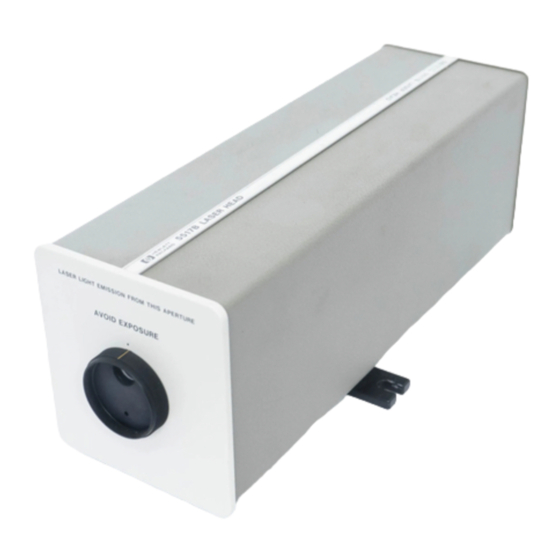
- Page 10 Figure 1-1. HP 5517B Laser Head...
- Page 11 Except as described below, the HP 5517C Laser Head is physically identical to the HP 5517B Laser Head. The primary difference between the two Laser Heads is that the difference between the two HP 5517C laser beam frequencies is approximately 2.8 MHz, versus the 2.1 MHz difference in the HP 5517B. The larger frequency difference allows measurements involving motion to be made at higher velocities (slew rates).
-
Page 12: General Information
1-6. The HP 5517B/C/D laser beam consists of two linearly polarized and mutually perpendicular (orthogonal) components separated in frequency by 1.9 - 2.4 MHz (HP 5517B), 2.4 - 3.0 MHz (HP 5517C), or 3.4 - 4.0 MHz (HP 5517D). The two components have light frequencies of and F . -
Page 13: Manual Organization
HP 5527A. 1-16. If an HP 5527B is not available (for use as a power source for an HP 5517B/C/D), an HP 5527A, an HP 10884A (or even an HP 5501A) can be used. The test, adjustment, and troubleshooting procedures in this manual do not depend on or require laser beam frequency. -
Page 14: Instruments Covered By This Manual
1-23. SAFETY CONSIDERATIONS 1-24. The HP 5517B/C/D Laser Head is designed to receive its power from a Safety Class I product. It is designed and tested in accordance with international safety standard IEC* 348. It is also a Class 11 Laser Product certified as conforming to U.S. - Page 15 HP 5517B to the HP 5501A system power supply and HP 10760A Counter using the HP 10791A/B/C Cable. Figure 2-4 illustrates the cables use in connecting the HP 5517B to the HP 5501A system power supply and the HP 10764C Fast Pulse Converter.
-
Page 16: Specifications
Safety Feature: Front shutter to clock Laser Beam Outputs: Reference signal: 1.9 - 2.4 MHz (5517B), 2.4 - 3.0 MHz (5517C), or 3.4 - 4.0 MHz (5517D) differential square wave (DC isolated). TTL levels are compatible with all Laser Transducer System inputs. -
Page 17: Recommended Test Equipment
Table 1-3. Recommended Test Equipment INSTRUMENT USE* CRITICAL SPECIFICATIONS RECOMMENDED EQUIPMENT (Equipment having equivalent characteristics maybe substituted) Signature Multimeter Detects TTL level signals HP 5005A/B Oscilloscope 100 MHz Bandwidth HP 1740A (if available) Laser Power Meter Range: 1 microwatt to 1 Graseby Optronics, Model 351L milliwatt (Phone 407-282-1408) -
Page 18: Options
3mm beam Option 009 9mm beam Option 030 Replace standard feet with 3 electrically insulated feet. The options listed below can be ordered with any HP 5517B/C/D Laser Head: Option AV4 Laser and Optics Users Manual Option 1BN MIL-STD 45662 Calibration... -
Page 19: Installation
SECTION II INSTALLATION 2-1. INTRODUCTION 2-2. This section provides installation instructions for the HP 5517B/C/D Laser Head including unpacking, inspection and reshipment, installation, operating environment, and storage. Installation includes information on grounding considerations, power supply requirements, power dissipation, fusing, dimensions, and mounting and fixturing. -
Page 20: Packaging For Reshipment
2-16. System Cabling 2-17. The HP 5517B/C/D Laser Head is designed for use with either the HP 5501A Laser Transducer System or the (Figure 2-1) HP 5527A Laser Position Transducer system. The HP 10791A/B/C Power Supply/Reference Cable... - Page 21 Figure 2-1. HP 10791A/B/C Power Supply /Reference Cable 2-21...
-
Page 22: Power And Signal Connections
Figure 2-2. HP 10793A/B/C Laser Head Cable 2-20. Power and Signal Connections 2-21. The HP 5517B/C/D Laser Head rear panel contains an 18-pin connector used for connecting its power and signal lines to other laser transducer system components. (Refer to Figures 2-2... - Page 23 Table 2-1. PC-Compatible System HP Product Number and Cables Additional Information Name Connects HP 5517D Laser DIN connector for power source mates with HP 10881A/B/C Laser Head to HP 10897B VMEbus or cable from HP 10884A Power Supply. Head Cable PC-compatible electronics.
- Page 24 Figure 2-4. Installation of Laser System Cables for HP 10895A VME-Axis Systems Figure 2-5. Installation of Laser System Cables for HP 10897B High Resolution Systems...
- Page 25 Figure 2-7. Typical HP 5501A Laser Transducer System Connections (HP 5517B to HP 10764A Interconnection Diagram)
- Page 26 Figure 2-7. Typical HP 5501A Laser Transducer System Connections (HP 5517B to HP 10764C Interconnection Diagram)
- Page 27 Figure 2-8. Typical HP 5527A Laser Position Transducer Connections Table 2-2 HP 5517B Laser Head System Signal Chart Pin Number Signal Name No Connection ~ MEAS (No Connection) MEAS (No Connection) Signal Return ~ REF G, H Ground +15V Sense...
-
Page 28: Grounding Considerations
2-28. Fusing 2-29. The HP 5517B/C/D has three internal fuses: two that protect the laser head's ±15V lines (both of which are located on the Al Connector Board Assembly), and one fuse that protects the +15V line to the digital and analog circuitry located on the A3 Controller/Reference Assembly (and is located on the A3 Assembly) All three fuses are accessible by removing the left and right covers of the laser head. -
Page 29: Dimensions
+15 Volt Figure 5-1 A1F2 2110-0027 0.12 No Time Delay -15 Volt Figure 5-2 A3F1 2110-0716 No Time Delay +15 Volt 2-30. Dimensions 2-31. Figure 2-9 shows the HP 5517B/C/D Laser Head dimensions. Figure 2-9. Mounting Details and Physical Characteristics... -
Page 30: Mounting And Fixturing
An external heat sink is not required but free air circulation around the laser head will ensure good performance. 2-34 In cases where vertical mounting of the HP 5517B/C/D is desired, care should be taken to minimize laser beam disturbances due to air turbulence caused by the HP 5517B/C heat exchange. It is most important to prevent... -
Page 31: Operating Environment
Temperature (Operating): 0 to 40°C (32 to 104°F) Relative Humidity (Operating): 0 to 95% Non-condensing Vibration: The HP 5517B/C Laser Head has been tested to withstand 0.25 mm (0.01 5 inch) peak-to- peak excursion at 15 to 55 Hz for 15 minutes. - Page 32 FROM THE HP 5517B'S REAR PANEL 3-5. The HP 5517B Laser Head is activated when +15 Vdc and -15 Vdc are applied to the unit. ±15 Volts is applied by connecting either the HP 10791A/B/C Power Supply/Reference Cable (used when connecting the laser head to the HP 5501A system electronics) or the HP 10793A/B/C Laser Head Cable (used when connecting the laser head to the HP 5527A electronics) to the rear panel connector (A1J2).
- Page 33 Figure 3-1. HP 5517B Front Panel Controls 3-8. HP 5517B LASER HEAD REAR PANEL INDICATORS AND CONNECTORS NOTE A TILDE ("~") PRECEDING A SIGNAL NAME INDICATES NEGATIVE- TRUE LOGIC LEVELS. Figure 3-2. 3-9. Following are descriptions of the HP 5517B rear panel features shown in...
- Page 34 +15V POWER ON GREEN LED LED lights when -15 Vdc power is applied to the HP 5517B. This LED extinguishes if the -15V fuse opens.. LED remains off while heating rod to normal operating 3. -15V POWER ON GREEN LED temperature.
- Page 35 3-11. When power is applied to the HP 5517B, an internal state machine resets the laser head to a warmup mode. This mode is used to establish the initial operating temperature of a glass rod that controls the laser cavity length.
- Page 36 Tables 4-12 and 4-13 contained in of the HP 5501A Laser Transducer Operating and Service Manual (HP Part Number 05501-90028). If desired, some form of time-out algorithm can be added to check if the HP 5517B warms up within 10 minutes.
- Page 37 Table 3-2 Table 4-12 3-21. shows the program steps used to modify in the HP 5501A Laser Transducer Operating and Service Manual. The program uses the HP 10760A x-axis card to monitor the laser warmup. Table 3-3 Table 4-13 3-22. shows the program steps used to modify in the system manual.
- Page 38 Table 3-2. Program Modifications (or Table 4-12 in the HP 5501A gab ^warmup": Branch to subroutine to monitor laser status ______ Laser Transducer Operating and Service Manual _____ 38: "warmup":clr 7; Send Device Clear; Send Remote Enable rem 7 X" wrt 709, "0O0 Send 10740A Backplane Reset, preset x-axis counter and select normal resolution...
- Page 39 HP 5517B Operation Table 3-3. Program Modifications for Table 4-13 in the HP 5501A ______ Laser Transducer Operating and Service Manual ____ °* gsb "warmup* Branch to warmup subroutine monitor laser status 66: "wannup :wtb 2,0,0,0 System reset - 10746A 16-bit mode...
- Page 40 Table 3-4. Modified HP 10745A HP-IB Interface Program (Replaces Table 4-12 in the HP 5501A Laser Transducer Operating and Service Manual) 0: gsb "warmup" 1: wrt 709,"006X" 2: wrt 709, "2V30" 3: red 709,C 4: 0>E 5: "loop":E+l)e; if E=10;gto -3 6: wrt 709,"102X30"...
- Page 41 24: B)r3 25: wtb 2, 146, 3 26: 1}F 27: gsb "in" 28: B)r4 29: fmt 1,2f10.0,f10. 7 30: wrt .1,r3-160,r4-160,C 31: if abs(X-r3)<=rl/(.158*C) and abs (Y-r4)<=r2/(.158*C);gto "newdest" 32: gto "newsample" 33: "in":rdb(2)}B;if B<0;65536+B)B 34: if B>=61440;gto "er" 35: rdb(2)}G;if G<0;65536+G}G 36: int (B/4096))D 37: B-4096*D)B 38: (6S536*B+G)*tn"(2-D)}B;ret...
- Page 42 SECTION IV PERFORMANCE TESTS 4-1. INTRODUCTION 4-2. This section contains a performance test for the HP 5517B Laser Head. A test record is included to record test results for future comparison. 4-3. RECOMMENDED TEST EQUIPMENT 4-4. Test equipment requirements are included in the following procedure. Detailed critical specifications for the...
- Page 43 Power Meter, United Detector Technology (Model No. 351 L) 4-13. Procedure a. Connect the Hp 5517B to either the Hp 5501A or HP 5527A system (or any suitable dual DC voltage power supply such as the HP 6255A) using HP 10791A/B/C or HP 10793A/B/C cable.
- Page 44 SECTION V ADJUSTMENTS 5-1. INTRODUCTION 5-2. This section describes adjustments and checks required to return the HP 5517B Laser Head to peak operating capabilities when repairs have been made. Included in this section are the test equipment required, equipment setups, and procedures to perform the adjustments.
- Page 45 Digital Voltmeter to A3TP11, and connect the negative lead to A3TP1. d. If the HP 5517B power has been disconnected for at least 2 hours, reconnect ±15 Volt system power supplies and continue with the adjustment procedure in paragraph 5-16.
- Page 46 +15VFUSE(F1) TEST POINT 1 TEST POINT 11 A3R16 (SET TEMP) (GROUND) (HEATER SENSE) Figure 5-1. A3 Controller/Reference Board, Jumpers, Test Points, and Adjustment Locations 5-20. Procedure: Before measuring the laser tube current, observe the safety precautions in paragraph 5-4, and then proceed as follows: a.
- Page 47 Return all A3 jumpers moved in step 5-20(d) back to NRM position (left-most position). HIGH VOLTAG E AREA Figure 5-2. 5517B High Voltage Area and Anode Lead Instrument Model Number: HP 5517B Page of Instrument Serial...
- Page 48 ±0.1 mA Laser Output µW >180 µW Power (Calculated) 3.5 Laser Tube Current mA ±0.1 mA Instrument Model Number: HP 5517B Page of Instrument Serial Number: HP5517B LASER HEAD ADJUSTMENT RECORD DESCRIPTION DATE MEASURED ACTUAL READING LIMITS Laser Output µW...
- Page 49 ("Contacting Hewlett-Packard"). Please have the following information at hand when you contact HP for help: • Instrument Model Number (example "HP 5517B"). • Complete instrument Serial Number (example "1234A56789"). Information about where to find the serial number is given in the preface of this manual in the "HOW TO USE THIS MANUAL" section.
-
Page 50: Cabinet Parts And Hardware
6-17. For mail correspondence, use the address below: Hewlett-Packard Support Materials Roseville P.O. Box 1145 Roseville, Ca 95661-1145 CABINET PARTS AND HARDWARE: 6.19 To locate and identify miscellaneous chassis parts, refer to Figure 6-1 This figure provides an exploded view of the Laser Head, with the parts identified by reference designations;... - Page 51 HP 551767C/D Replaceable Parts Table 6-1. Reference Designations REFERENCE DESIGNATIONS Abbreviations ■ delay Ins - assembly < -reaiy 3 iransformef > attenuator, » annuncalor *zoi inductor TB - terminal board isolator sgnakng device termination (audible or v«uai,: 3 metre TC 3 r^hermocpupla lamp;...
- Page 52 Reference HP Part Description Designation Number Code Mfr Part Number 05517-60004 CONNECTOR BOARD ASSEMBLY 28480 05517-60004 A1C1 0160-4557 CAPACITOR-FXD 1UF±20%50VDCCER 16299 CAC04X7R104M050A A1C2 0180-4132 CAPACITOR-FXD 6 8UF 10% 35V AX T322D685K035AS A1C3 0150-4557 CAPACITOR-FXD 1UF ±20% 50VDC CER 16299 CAC04X7R104M050A A1C4 0180-2867 28480...
- Page 53 A3C23 0160-4554 CAPACITOR-FXD 01UF ±20% 50VDC CER 2B4B0 0160-4554 A3C24 0160-4554 CAPACITOR FXD 01UF ±20% 50VDC CER 284 80 0160-4554 A3C25 NOT ASSIGNED A3C26 0160-0576 CAPACITOR-FXD 1UF ±20% SOVDC CER 28480 0160-0576 A3C27 0160-0576 CAPACITOR-FXD 1UF ±20% 50VDC CER 2B480 0160-0576 A3C28 0180-0309...
- Page 54 A3R23 0698-3260 1 RESISTOR 464K 1% 125W F TC=0+-100 28480 0698-3260 A3R24 0757-0438 RESISTORS 11K 1% .125W F TC=0+-100 24546 CT4-1/8-TO-S111-F A3R25 0757-0442 3 RESISTOR 10K 1% .125W FTC-0+-100 24546 CT4-1/8-TO-1002-F A3R26 0757-0442 RESISTOR 10K 1% 125W FTC*0+-100 24546 /8-TO-1002-F A3R27 0699-0069 RESISTOR 2 15M 1% 125W F TC=0+-100...
- Page 55 CONNECTOR 4-PIN F POST-TYPE i 1251-6778 INSULATOR-TRANSISTOR. NYLON 1251-6778 0340-0907 0340-0907 05517- 28480 05517-60201 05517-60216 A5 A5 A5 A5 A6 LASER TUBE, 5517B LASER 60201 28480 05517-60225 05517-60220 TUBE, 5517C (180 MW) LASER 05517- 28480 TUBE, 5517C (>400 MW) 05501-60101 60216...
- Page 56 40003 05501- shutter 28480 05501-40004 40004 See introduction to this section for ordering information 'Indicates factory selected value 05501- cover. right - 5517b/c 28480 05501-00010 00010 6-56 05517- cover. left-5517b 28480 05517-60205 60205 Figure 6-1. 5517B Laser Head Exploded View...
-
Page 57: Manual Changes
Office (listed at the back of this manual) if the change information is missing. 7-6. OLDER INSTRUMENTS 7-7. To adapt this manual to older instruments having a serial prefix lower than 3014A for the 5517B or 3002A for Table 7-1. - Page 58 To backdate 5517B Laser Heads from Series 3014A, make the following changes: Page 6-5, Table 6-3. HP 5517B Board Assemblies Replaceable Parts (Continued) Change A2 Power Supply part number from 0950-0470 to 05518-60303 for the 5517B. NOTE POWER SUPPLY PART NUMBER 0950-0470 HAS THREE INPUT WIRES. POWER SUPPLY PART NUMBER 05518-60303 HAS TWO INPUT WIRES.
- Page 59 OF THE HIGH VOLTAGE POWER SUPPLY ASSEMBLY A2. Add the following NOTE and figure after the WARNING: NOTE AFTER SERVICING THE HP 5517B, BE SURE TO SET A1S2 TO THE NORM POSITION, OTHERWISE POWER TO THE HVPS WILL BE DISCONNECTED.
- Page 60 Change paragraph 8-74, d, to read as follows: d. Disconnect power and remove the covers of the HP 5517B. Set A1S2 to TEST and verify that all boards are seated correctly and all test jumpers on the A3 board are in the left-most position (NRM).
- Page 61 REMOVED AND THE TEST-NORM SWITCH A1S2 IN THE TEST POSITION. Paragraph 8-89 Change step 1 to read as follows: Check that A1S2 is set to NORM when HP 5517B covers are on or TEST when the covers are off. Replace Figure 8-17...
- Page 62 Replace step u with the following: u. If ending troubleshooting procedures at this point, disconnect power from HP 5517B Laser Head, set all test jumpers to their left-most (normal) positions, return TEST-NORM switch A1S2 to NORM, and replace laser head front panel and side covers.
- Page 63 Replace step a with the following: a. With power disconnected from the Hp 5517B, Set the TEST-NORM switch to TEST, the -REF ON jumper to LO, and HTR OK jumper to HI. Apply power to HP 5517B. Does the READY LED eventually start blinking then remain on continuously? If no, see HP 5517B Trouble Isolation Procedure, paragraph 8-74 and procedures recommended therein.
- Page 64 CHANGE 4 To backdate A3 Control/Reference Board to Date Codes below 91021: Table 6-3. Page 6-6, 5517B Board Assemblies Replaceable Parts: Change A3Q3 from 1853-0347 to 1853-0332 TRANSISTOR PNP SI DARL PD=70W. Table 6-3. Page 6-10, 5517B/C Replaceable Parts: Add H19, 1200-0081, INSULATOR-FLG BUSHING NYLON.
-
Page 65: Service
SECTION VIII SERVICE 8-1. INTRODUCTION 8-2. This section contains service information for the HP 5517B Laser Head. Also included are safety considerations, theory of operation, block diagrams, schematic diagrams, component locators, and troubleshooting and repair procedures. Other useful service information also provided in other sections of this manual include: performance tests in Section IV, adjustments in Section V, and exploded view illustrations and parts lists in Section VI. - Page 66 NECESSARY PARTS ARE CONNECTED TO THEIR PROTECTIVE GROUNDING MEANS. WARNING FROM 1.2 KILOVOLTS TO 12 KILOVOLTS DC IS PRESENT ON THE ANODE OF THE LASER TUBE IN THE HP 5517B. EXERCISE EXTREME CAUTION WHEN WORKING INSIDE THE INSTRUMENT. THE HIGH VOLTAGE COULD...
- Page 67 67-3...
-
Page 68: Safety Symbols
8-16. Safety Symbols 8-17 . The following safety symbols are used on the instrument or in this manual. Instruction manual symbol. The product will be marked with this symbol when it is necessary for the user to refer to the instruction manual in order to prevent damage to the instrument. Indicates dangerous voltage at input or output terminals that may exceed 1000 volts. -
Page 69: Before And After Service Product Safety Checks
8-25. Before the laser light is emitted from the HP 5517B, a portion of it is sampled by the sampler assembly. Most of this sample feeds into the reference receiver while the remainder is used to control laser tuning. The reference receiver generates the reference frequency signal by mixing the two laser frequencies. - Page 70 HP5517B Service 8-27. The High Voltage Power Supply (HVPS) requires +15 Vdc as input. This supply generates up to 12 kilovolts DC at power-on. After the laser emission starts, the power supply output drops to approximately 1.2 kilovolts DC. Figure 8-4. Feedback Loop During Warmup Mode 8-33.
- Page 71 8-36. Optical Mode Tuning Figure 8-5. Warmup Mode Timing Diagram 8-37. In optical mode, the state machine switches the subtracting sample and hold inputs from warmup feedback to optical feedback as shown in Figure 8-6. The optical mode feedback controls the laser cavity length by measuring and comparing the power of the two laser frequency components.
- Page 72 Figure 8-7. A6 Sampler Assembly, Exploded View 8-39. When the state machine excites the liquid crystal into its active state (see Figure 8-8), the laser beam passes through the liquid crystal unaltered. The polarizer blocks the horizontal component and passes the vertical component onto the photodiode.
- Page 73 HP 5517B. The vertical component is polarized perpendicular to the horizontal component. The laser beam is collimated to minimize variations in beam diameter as it travels away from the laser head.
-
Page 74: Reference Receiver
8-49. REAR PANEL LED INDICATORS 8-50. The status LEDs, mounted on the HP 5517B/C/D's rear panel, provide status information on power supply input (±15 Volts), fuses, laser output and tuning, and the reference frequency output. See Figure 3-2 for a more detailed description of the LEDs. -
Page 75: Assembly Removal Instructions
Paragraph 8-53, Table 8-1, and Figure 8-9 have been deleted. 8-54. ASSEMBLY REMOVAL INSTRUCTIONS 8-55. Figure 6-1, the exploded view diagram in Section VI, shows the HP 5517B assembly locations, provides access and removal information, and gives assembly part number references. - Page 76 Install the A1 Connector Board Assembly; perform the reverse of the removal procedure. 8-59. To remove the A2 High Voltage Power Supply from the HP 5517B chassis, perform the following procedure. a. Remove ±15 Volt power from HP 5517B Laser Head.
- Page 77 Two screws (H5) secure the Sampler Mount to the shield (MP10). Figure 8-11. Factory-adjusted Sampler Mount 8-62. To remove the A5 Laser Tube Assembly (HP Part Number 05517-60201) from the HP 5517B chassis, perform (M1) the following procedure.
-
Page 78: Quick Tuning Checkout Procedure
8-63. If replacement of the clear optical window (which is cemented to the HP 5517B front panel) becomes necessary, proceed with the following procedure: a. Remove front panel and side covers as described in paragraph 8-57. b. Remove mechanical parts MP7 and MP6 from front panel (MP3). -
Page 79: Testing The Liquid Crystal Switch
Figure 8-14. Quick Tuning Check Waveform Display Disconnect the test equipment and set HEATER jumper JMP 7 to NRM. Replace HP 5517B covers. 8-70. Testing the Liquid Crystal Switch 8-71. The following material and test equipment is required for the test: A white piece of cardboard. - Page 80 Test Polarizer (HP Part Number 1000-0616) 8-72. To test the liquid crystal, proceed as follows: Figure 8-15 a. Remove the liquid crystal from the sampler assembly as shown in below...
-
Page 81: Hp 5517B Trouble Isolation Procedure
Do not apply DC voltages across the liquid crystal switch. Sustained dc current flow through the liquid crystal may damage the device. 8-73. HP 5517B/C/D Trouble Isolation Procedure 8-74. Before HP5517B/C/D trouble isolation is attempted, the Laser Head Block Diagram Description paragraphs 8-... - Page 82 A3TP10 (labeled "-15"): -14.7 V to -1 5.3 V Turn the power off for a few seconds, then back on. Observe READY LED on the HP 5517B/C/D. Find the READY LED description in steps g through j that matches your observation and follow that step.
-
Page 83: A1 Connector Board Circuit Theory
(LASER ON LED) lights when the high voltage supply is powered. AT DS7 (READY LED) lights when the HP 5517B/C/D is ready for use. A1 R12 is used to adjust laser current as per the adjustment procedures in Section V. -
Page 84: A2 High Voltage Power Supply Circuit Theory
8-85. The following procedure can be used as an operational check of the rear panel LEDs. Perform only if a problem is suspected. a. With power disconnected from laser head, remove HP 5517B instrument covers as described in paragraph 8-57, b. -
Page 85: High Voltage Power Supply Troubleshooting
DANGEROUS HIGH VOLTAGE EXISTS. 8-88. HIGH VOLTAGE POWER SUPPLY TROUBLESHOOTING WARNING FROM 1.2 KILOVOLTS TO 12 KILOVOLTS DC IS PRESENT ON THE ANODE OF THE LASER TUBE IN THE HP 5517B. EXERCISE EXTREME CAUTION WHEN WORKING INSIDE THE INSTRUMENT. THE HIGH VOLTAGE COULD... -
Page 86: A3 Controller/Reference Bd & A4 Sampler Bd Circuit Theory
NOTE IF A POWER SUPPLY PROBLEM SEEMS INTERMITTENT, GENTLY TAPPING THE HVPS WITH A SCREWDRIVER WILL INDUCE THE PROBLEM FOR TEST PURPOSES. Figure 8-17. High Supply, Schematic Diagram Voltage Power 8-90. A3 CONTROLLER/REFERENCE BD & A4 SAMPLER BD CIRCUIT THEORY 8-91. Introduction Figure 8-22 8-92. - Page 87 8-97. The dividers, consisting of A3U4B and A3U6, convert the 100 Hz oscillator signal into the desired periods. The first stage of the divider is U6, a dual 4-bit counter, which divides the 100 Hz by 256. The last output of A3U6 at Pin 8 has a period of 2.56 seconds (nominal).
- Page 88 If REF ON (a signal from the Reference Receiver) is low, the entire circuit will be reset by the Power- on-Reset circuit. Otherwise A3U1F and A3U19E turn on the rear panel READY (and A3DS1) indicator LED indicating that the HP 5517B is ready for use. 8-104. Liquid Crystal (D) 8-105.
- Page 89 8-116. The first counter (A3U6) in the divider section controls the liquid crystal and the sample and hold circuits. A sample and hold is performed once per cycle of T1.28 alternating between the vertical and horizontal components Figure 8-8 [see (Optical Mode Timing Diagram)].
- Page 90 8-129. +15V and -15V are supplied by the system power supplies via the rear panel connector A1J2. Fuse A3F1 protects both the A3 digital and analog control circuits. The +5V is generated by regulator A3U7. A3CR2 protects A3U7. A3C5 stabilizes A3U7 and A3C4 filters A3U7 +5V output. Output +15V is the supply after being filtered by A3L2 and A3C11.
- Page 91 Warm-up Error Amplifier g. Power Supplies h. Reference Receiver Consult paragraph 8-67, HP 5517B/C/D Trouble isolation, to determine which procedure to use. 8-134. Standard Troubleshooting Procedures ■ 8-135. In the following tests, reference is frequently made to "localize the defective element by standard troubleshooting procedures".
- Page 92 Upon successful completion of a check, unless otherwise specified, return all test jumpers to their original position [i.e., left-most NRM position)]. NOTE A TILDE ("-") PRECEDING ALL SIGNALS INDICATES NEGATIVE-TRUE LOGIC. a. With power disconnected, remove front panel and side covers as described in paragraph 8-57. b.
- Page 93 or - 300 Hz F(U4 pin 15/10) or - 3 Hz f(U4 pin 1/10) or - 3 Hz If no problem is found, proceed to step f. Test jumpers and shorting wires remain in place if continuing with step f. If ending test procedure at this point, remove shorting wires and return all test jumpers to their left-most position.
- Page 94 position. The Digital Section is OK. If A3U2C (Pin 8) doesn't go high, check divider and state machine circuitry. See A3 Power Amp section for additional information. s. Signature Analysis: CAUTION When taking signatures, ensure that heater test jumper is in the off position. Damage to the high voltage power supply or laser tube assembly could result if these instructions are not adhered to.
- Page 95 Table 8-4. Signature Table 1119 41A5 4UHP CCPC 6678 4CCA 41A5 CCPC F9C3 0000 7U30 41A5 0000 FP96 0000 41A5 8816 ■ 41A5 8816 , FP96 8A5F P861 F09F 27HH 7130 F9C3 4 A3 9 41A5 0000 4UHP CU8C 0000 xxxx UA4P 41A5...
- Page 96 The bottom edge of the polarizer should be parallel to the base of the HP 5517B/C/D. Measure A3TP16 voltage. Is it<0.2V? If yes, go to step c. If not, go to step b. b. Rotate polarizer 90 degrees. Is A3TP16 voltage <0.2 V? If yes, go to step c. If no, go to step f.
- Page 97 If ending troubleshooting procedures at this point, disconnect power from HP 5517B Laser Head, set all test jumpers to their left-most (normal) positions, and replace laser head front panel and side covers.
- Page 98 Is A3U15 (Pin 7) between +0.10 and +0.20? If yes, the warmup error amplifier is OK. If no, A3R5E, R48D, U8A orU15 is faulty. If ending troubleshooting procedures at this point, disconnect power from HP 5517B Laser Head, set all test jumpers to their left-most (normal) positions, and replace laser head front panel and side covers.
- Page 99 Power supply components are located on both A1 and A3. 8-150. Reference Receiver Troubleshooting a. With power disconnected from the HP 5517B, the -REF ON jumper to LO, and HTR OK jumper to HI. Apply power to HP 5517B. Does the READY LED eventually start blinking then remain on continuously? If no, see HP 5517B Trouble Isolation Procedure, paragraph 8-74 and procedures recommended therein.
- Page 100 If not, check A3R46, C27, or CR5. A3CR5 can be checked by removing power from the HP 5517B and checking for diode action using a DC ohmmeter. Resistance measured in the reverse direction should be much larger than the resistance measured in the forward direction.
- Page 101 2. Remove A4 Sampler Board. 3. Rest the test polarizer (HP Part Number 1000-0616), which is supplied with the HP 5517B, against the exposed Reference Receiver exit port of the A6 Sampler Assembly. The test polarizer serves as a viewing screen for examining the laser beam, which is normally incident on the Reference Receiver photodiode.