Table of Contents
Advertisement
Quick Links
Advertisement
Table of Contents
Troubleshooting

Related Manuals for Agilent Technologies 5517B


Summary of Contents for Agilent Technologies 5517B
- Page 1 Agilent 5517B/BL/C/D/DL/FL Laser Head User’s Guide Agilent Technologies...
- Page 2 Notices © Agilent Technologies, Inc. 2009 Manual Part Number Restricted Rights Legend No part of this manual may be reproduced 05517-90077 If software is for use in the performance of in any form or by any means (including a U.S. Government prime contract or sub-...
- Page 3 User’s Guide This guide describes how to use the Agilent 5517B/BL/C/D/DL/FL Laser Head. The information in this guide applies to laser heads having the serial prefix number listed below. SERIAL PREFIX NUMBER US4627 for 5517B US4605 for 5517BL US4627 for 5517C...
- Page 4 Certification Safety Considerations Safety Considerations (contd) and Warranty General Certification This product and related Agilent Technologies certifies that documentation must be reviewed this product met its published Indicates Alternating for familiarization with this safety current. specification at the time of markings and instructions before shipment from the factory.
- Page 5 - 15V POWER ON Split Freq: 3.74 MHz ICES/NMB-001 READY ISM 1 - A N10149 LASER ON July, 2005 Agilent Technologies Inc. 5301 Stevens Creek Blvd. Santa Clara, CA 95051 Made in U.S.A. of domestic and foreign content COMPLIES WITH 21 CFR 1040.10 AND 1040.11...
- Page 6 E N D P R O D U C T L A S E R S A F E T Y C O N S I D E R A T I O N S The Agilent 5517B/BL/C/D/DL/FL Laser Head complies with U.S.
-
Page 7: Table Of Contents
Contents Contents 1 General Information Introduction Description of the Agilent 5517B/BL/C/D/DL/FL Laser Head Manual Organization Options Accessories Cables Power Supply Related Documents 2 Laser Head at a Glance Laser Head Front Panel at a Glance Laser Head Rear Panel at a Glance... - Page 8 All Agilent laser systems share a similar configuration A controller is required for all laser positioning systems Setting Up the System Electronics Install the laser electronics board in the PC Connect the electronics cables Power up the laser head viii Agilent 5517B/BL/C/D/DL/FL User’s Guide...
- Page 9 To remove the A3 Controller/Reference Board To remove the A1 Connector Board To remove the A4 Sampler Board To remove the A5 Laser Tube Assembly and A2 Power Supply 8 Specifications Introduction Calibration cycle Specifications and characteristics Specifications and Characteristics Index Agilent 5517B/BL/C/D/DL/FL User’s Guide...
- Page 10 Contents Agilent 5517B/BL/C/D/DL/FL User’s Guide...
- Page 11 Figure 24. DS4, DS6, Q3, TP1 and TP8 locations on A3 Controller/Reference Board Figure 25. Laser head cover removal Figure 26. Agilent 5517B/C/D Laser Head dimensions and mounting location Figure 27. Agilent 5517BL/DL/FL Laser Head dimensions and mounting location Agilent 5577B/BL/C/D/DL/FL User’s Guide...
- Page 12 Figures Agilent 5577B/BL/C/D/DL/FL User’s Guide...
- Page 13 Tables Tables Table 1. Summary of the laser head major operating characteristics Table 2. Laser head mechanical and electronic assembly summary Table 3. Available options Table 4. Laser Head Cables Table 5. Terminal connections (three spade lugs) Table 6. 18-Pin Laser Head Cable and Rear Panel Connector pin assignments Table 7.
- Page 14 Tables Agilent 5577B/BL/C/D/DL/FL User’s Guide...
-
Page 15: General Information
Agilent 5517B/BL/C/D/DL/FL Laser Head User’s Guide General Information Introduction, 2 Description of the Agilent 5517B/BL/C/D/DL/FL Laser Head, 2 Manual Organization, 5 Options, 6 Accessories, 7 Related Documents, 9 Agilent Technologies... -
Page 16: Introduction
This manual contains information required to install, operate, test, adjust, and service the Agilent 5517B/BL/C/D/DL/FL Laser Head. The information in this manual is specific to the Agilent 5517B/BL/C/D/DL/FL Laser Head, unless otherwise stated. This manual does not contain information on how to set up a laser interferometer position measurement system. -
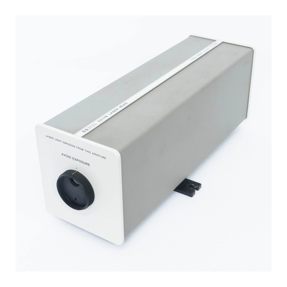
Page 17: Figure 1. Agilent 5517B/C/D And 5517Bl/Dl/Fl Laser Heads
General Information The physical differences between the 5517B/C/D and 5517BL/DL/FL are: • 5517B/C/D has a non- vented cover as shown in Figure • 5517BL/DL/FL has a vented cover for heat isolation as shown in Figure • 5517B/C/D beam height is 79.5 mm (see Figure 26 on page 78). -
Page 18: Table 1 Summary Of The Laser Head Major Operating Characteristics
0 5 5 1 7 - 6 0 0 3 1 B e l o w U S 4 4 1 0 T w o - p i e c e 0 5 5 1 7 - 6 0 0 0 3 Agilent 5517B/BL/C/D/DL/FL User’s Guide... -
Page 19: Manual Organization
Covers product description, manual organization, options, and available accessories. Chapter 2, “Laser Head at a Glance” — Provides a visual introduction to the Agilent 5517B/BL/C/D/DL/FL Laser Head and an overview of its aperture, indicators, and connector. Chapter 3, “Installation” —... -
Page 20: Options
* Support Option W50 is available only at the time of purchase. Service contracts are available from Agilent for instruments which did not include support options at the time of purchase. For information, contact your nearest Agilent Technologies Sales and Support office (offices are listed at the back of this manual). Agilent 5517B/BL/C/D/DL/FL User’s Guide... -
Page 21: Accessories
Agilent 10780C/F, or Agilent E1708A, or Agilent E1709A receivers. The 10884B plugs into ac line power. Alternatively, you can design your own power supply. See Table 5 page 21 for power supply requirements. Agilent 5517B/BL/C/D/DL/FL User’s Guide... -
Page 22: Table 4 Laser Head Cables
Due to higher reference frequencies (and corresponding higher velocities of motion), laser heads with reference frequencies above that of the 5517C do not work with the 10895A or 10885A. For use with the 10884B Power Supply. The N1251 is only available in model suffix B. Agilent 5517B/BL/C/D/DL/FL User’s Guide... -
Page 23: Related Documents
R e l a t e d D o c u m e n t s • Agilent Laser Head User’s Guide, (this document) (p/n 05517- 90077) • Agilent Laser and Optics User’s Manual (p/n 05517- 90086) • Agilent Laser and Optics User’s Manual, CD (p/n 05517- 13602) Agilent 5517B/BL/C/D/DL/FL User’s Guide... - Page 24 General Information Agilent 5517B/BL/C/D/DL/FL User’s Guide...
-
Page 25: Laser Head At A Glance
Agilent 5517B/BL/C/D/DL/FL Laser Head User’s Guide Laser Head at a Glance Laser Head Front Panel at a Glance, 12 Laser Head Rear Panel at a Glance, 13 Agilent Technologies... -
Page 26: Laser Head Front Panel At A Glance
1 S h u t t e r The shutter, also known as the aperture ring, allows for three aperture settings: Open — used during normal operation. Reduced — used during alignment of the measurement axes. Closed — closes the aperture. Agilent 5517B/BL/C/D/DL/FL User’s Guide... -
Page 27: Laser Head Rear Panel At A Glance
It also allows the external power supply ±15V and reference signals (REF and ~ REF), to be connected to other system components via the laser head cables. Table 6 lists all the power and signal lines available on page 24 at the rear- panel connector. Agilent 5517B/BL/C/D/DL/FL User’s Guide... - Page 28 Laser Head at a Glance Agilent 5517B/BL/C/D/DL/FL User’s Guide...
-
Page 29: Installation
Agilent 5517B/BL/C/D/DL/FL Laser Head User’s Guide Installation Introduction, 16 Preparing the Laser Head for Use, 16 Installing the Laser Head, 17 Connecting the Laser Head Cables, 18 Electrical Considerations, 25 Mounting Considerations, 27 Powering Up the Laser Head, 30 Agilent Technologies... -
Page 30: Introduction
Installation I n t r o d u c t i o n This chapter provides installation instructions for the Agilent 5517B/BL/C/D/DL/FL Laser Head. Installation includes information on grounding considerations, power supply requirements, power dissipation, fusing, dimensions, and mounting and fixturing. -
Page 31: Warranty Claims
• Beam- directing optics • Interferometers • Receivers • Cables For details about specific products, refer to their separate manuals. Visit the Agilent web site for lasers at www.agilent.com/find/lasers for a complete selection of products, literature and manuals. Agilent 5517B/BL/C/D/DL/FL User’s Guide... -
Page 32: Connecting The Laser Head Cables
This connector is keyed to fit together only one way. Align the tabs and push the connectors together. If you are using the Agilent 10881A/B/C or N1251B cable, go to step 5. If you are using the Agilent 10881D/E/F Cable, skip to step 6. Agilent 5517B/BL/C/D/DL/FL User’s Guide... -
Page 33: Figure 2 Agilent 10881A/B/C Laser Head Cable
Plug the ac line cord into an operating ac line outlet. The 10884B power supply has no power switch. As soon as it is plugged in, it will provide output power and the Power ON LED will light. Figure 2 Agilent 10881A/B/C Laser Head Cable. Agilent 5517B/BL/C/D/DL/FL User’s Guide... -
Page 34: Figure 3 Agilent N1251B High Performance Laser Head Cable
Connecting Agilent 10881D/E/F to a customer- supplied power supply: Connect the three spade lugs to the terminals of a power supply other than the 10884B as shown in Table Connect the power supply to ac line and turn it on. Agilent 5517B/BL/C/D/DL/FL User’s Guide... -
Page 35: Figure 4 Agilent 10881D/E/F Laser Head Cable
There are a variety of receivers and receiver cables to choose from. For more information on the receivers, cables and axis boards, see the Laser and Optics User's Manual or the individual receiver and axis board manuals. Agilent 5517B/BL/C/D/DL/FL User’s Guide... -
Page 36: Figure 5 Agilent 10791A/B/C Laser Head Cable
- turn to secure the cable to the mating connector. See Table 6 on page 24 for pin- outs of this connector. Plug the smallest connector on the laser head cable into the Reference connector on the axis board. Agilent 5517B/BL/C/D/DL/FL User’s Guide... -
Page 37: Figure 6. Installation Of Laser System Cables
Agilent 10884B Power Supply Cable (Part of Agilent 10884B) Figure 6 Installation of laser system cables Table 6 lists all of the power and signal lines available at the rear panel connector of the laser head. Agilent 5517B/BL/C/D/DL/FL User’s Guide... -
Page 38: Table 6 18-Pin Laser Head Cable And Rear Panel Connector Pin Assignments
MEAS (No connection) Signal Return ~REF G, H Ground +15V Sense +15 Volts –15 Volts +15 Volts N, P Cable Shield Signal Return Ground +15 Volts Cable Shield 18-pin (socket) rear connector 18-pin (plug) cable connector Agilent 5517B/BL/C/D/DL/FL User’s Guide... -
Page 39: Electrical Considerations
P o w e r d i s s i p a t i o n The laser head dissipates approximately 23 watts during operation. F u s i n g The following fuse information applies to all laser heads. Agilent 5517B/BL/C/D/DL/FL User’s Guide... -
Page 40: Figure 7 A1 Connector Board, Component Side, Showing Fuse Locations And High Voltage Connectors
2 1 1 0 - 1 3 8 1 For A3 Controller/Reference Board p/n 05517-60003. For A3 Controller /Reference Board p/n 05517-60031and 05517-60032. Figure 7 A1 Connector board, component side, showing fuse locations and high voltage connectors Agilent 5517B/BL/C/D/DL/FL User’s Guide... -
Page 41: Mounting Considerations
Because there is some heat dissipation from the laser heads, you should choose the mounting method and location with care. Where possible, mount the laser head away from the measuring area, to avoid any thermal effects. Agilent 5517B/BL/C/D/DL/FL User’s Guide... -
Page 42: Heat Flow Considerations
M a g n e t i c s h i e l d i n g Agilent laser heads contain a permanent magnet. When installing an Agilent laser measurement system in an application sensitive to magnetic fields, shielding around the laser head may be required. Agilent 5517B/BL/C/D/DL/FL User’s Guide... -
Page 43: Mounting Plane Tolerance
(depending on the laser head model you are using, refer to Figure 26 on page 78 or Figure 27 page 79 for exact locations and dimensions). The mounting feet may be Agilent 5517B/BL/C/D/DL/FL User’s Guide... -
Page 44: Powering Up The Laser Head
The 5517B/C/D Laser Head requires a 90- minute warmup period to stabilize the frequencies before a reliable measurement can be made. The 5517BL/DL/FL Laser Head (vented cover) requires a typical warmup period of 45 minutes, but only if a fan and exhaust hose are connected to the vented cover;... -
Page 45: Performance Tests
Agilent 5517B/BL/C/D/DL/FL Laser Head User’s Guide Performance Tests Introduction, 32 Recommended Test Equipment, 32 Performance Tests, 33 Performance Test Record, 37 Agilent Technologies... -
Page 46: Introduction
U s e w i t h 1 0 8 8 4 B o r 1 0 8 8 1 D w h e n u s i n g t h e E 3 6 1 5 A . Agilent 5517B/BL/C/D/DL/FL User’s Guide... -
Page 47: Performance Tests
On the laser head, set the exit shutter of the turret assembly to the open position (largest aperture). See Figure10. LASER LIGHT EMISSION FROM THIS APERTURE AVOID EXPOSURE Open Position Shutter or (Aperture Ring) Figure 10 Front Panel Turret and Aperture Agilent 5517B/BL/C/D/DL/FL User’s Guide... -
Page 48: Figure 11 Measuring The Laser Beam Power With Power Meter Detector
. Figure 11 Measuring the laser beam power with power meter detector Record the date measured and actual reading on line 1 of the “Performance Test Record" on page 37. Agilent 5517B/BL/C/D/DL/FL User’s Guide... -
Page 49: Split Frequency Test
Connect the laser head LEMO connector to the Laser Breakout Box as shown in Figure12, and connect the connector from the Laser Breakout Box to the cable to Channel 1 on the frequency counter. Figure 12 Split frequency test setup Agilent 5517B/BL/C/D/DL/FL User’s Guide... -
Page 50: Wavelength Test
You can search the National Institute of Standards and Technology in the USA at the following web site: www.nist.gov. Agilent 5517B/BL/C/D/DL/FL User’s Guide... -
Page 51: Performance Test Record
5 5 1 7 D 3 . 4 t o 4 . 0 M H z 5 5 1 7 D L 4 . 4 M H z 5 5 1 7 F L 7 M H z Agilent 5517B/BL/C/D/DL/FL User’s Guide... - Page 52 Performance Tests Agilent 5517B/BL/C/D/DL/FL User’s Guide...
-
Page 53: Adjustments
Agilent 5517B/BL/C/D/DL/FL Laser Head User’s Guide Adjustments Introduction, 40 Safety Considerations, 40 Recommended Test Equipment, 41 Laser Head Adjustments, 41 Adjustment Test Record, 49 Agilent Technologies... -
Page 54: Introduction
. Agilent 5517B/BL/C/D/DL/FL User’s Guide... -
Page 55: Recommended Test Equipment
. The laser head cover will need to be removed for all adjustments. Refer to the cover removal procedure in the “Disassembly Procedures" on page 68. Agilent 5517B/BL/C/D/DL/FL User’s Guide... -
Page 56: Preheat Setting
48). Now, reconnect the laser head cable to the laser head to power it on. Connect the DMM negative (–) lead to ACOM or , signal ground. Connect the DMM positive (+) lead to A3TP11. Agilent 5517B/BL/C/D/DL/FL User’s Guide... - Page 57 The DMM should display a voltage reading from 5V to 7.5V (for standard tube) or 6.5V to 9V (for short tube). Record the date measured and the actual voltage read at A3TP11 on line 3 in the adjustment test record on the “Adjustment Test Record" page 49. Agilent 5517B/BL/C/D/DL/FL User’s Guide...
-
Page 58: Table 10. Setpoint Voltages At Tp11 And Tp15 - Standard Tube With 05517-60031 A3
Adjustments Table 10 Setpoint voltages at TP11 and TP15 – standard tube with 05517-60031 A3 Board Actual R14 Adjusted Actual R14 Adjusted Actual R14 Adjusted Reading Voltage Reading Voltage Reading Voltage V (TP11) V (TP15) V (TP11) V (TP15) V (TP11) V (TP15) 0.201 0.258... -
Page 59: Table 11 Setpoint Voltages At A3Tp11 And A3Tp15 - Short Body Tube
Adjustments Table 11 Setpoint voltages at A3TP11 and A3TP15 – short body tube* Actual R14 Adjusted Actual R14 Adjusted Actual R14 Adjusted Reading Voltage Reading Voltage Reading Voltage V (TP11) V (TP15) V (TP11) V (TP15) V (TP11) V (TP15) 0.201 0.281 0.236... -
Page 60: Table 12. Setpoint Voltages At Tp11 And Tp15 - Standard Tube With 05517-60003 A3
Adjustments Table 12 Setpoint voltages at TP11 and TP15 – standard tube with 05517-60003 A3 Board Actual R16 Adjusted Actual R16 Adjusted Actual R16 Adjusted Reading Voltage Reading Voltage Reading Voltage V (TP11) V (TP15) V (TP11) V (TP15) V (TP11) V (TP15) 0.201 0.258... -
Page 61: Figure 13. Jumper Locations On A3 Controller/Reference Board (05517-60031)
Adjustments Figure 13 Jumper Locations on A3 Controller/Reference Board (05517-60031) Figure 14 Jumper Locations on A3 Controller/Reference Board (05517-60003) Agilent 5517B/BL/C/D/DL/FL User’s Guide... -
Page 62: Figure 15 High Voltage Area And Anode Lead
Adjustments Figure 15 High voltage area and anode lead Figure 16 Three-pin high voltage power supply connector Agilent 5517B/BL/C/D/DL/FL User’s Guide... -
Page 63: Adjustment Test Record
5 V t o 7 . 5 V ( s t a n d a r d t u b e ) 6 . 5 V t o 9 V ( s h o r t t u b e ) Agilent 5517B/BL/C/D/DL/FL User’s Guide... - Page 64 Adjustments Agilent 5517B/BL/C/D/DL/FL User’s Guide...
-
Page 65: Using The Laser Head In A System
Agilent 5517B/BL/C/D/DL/FL Laser Head User’s Guide Using the Laser Head in a System Introduction, 52 Setting Up the System Electronics, 54 Aligning the Optics, 56 Making Measurements — An Example, 57 Solving Problems, 60 Agilent Technologies... -
Page 66: Introduction
Figure 17 shows the components of a typical single- axis Agilent laser system. All Agilent laser systems combine optics (interferometer and reflector), electronics, and opto- electronics (laser head and receiver) to make a highly accurate positioning system. Agilent 5517B/BL/C/D/DL/FL User’s Guide... -
Page 67: All Agilent Laser Systems Share A Similar Configuration
The optics and receiver must be aligned so the beam strikes the lens of the receiver to generate a measurement signal. Misalignment results in loss of the measurement signal. Agilent 5517B/BL/C/D/DL/FL User’s Guide... -
Page 68: A Controller Is Required For All Laser Positioning Systems
Connect the receiver cable to the back of the receiver and to one of the three MEASurement connectors* on the electronics board. * To line up the connectors for the electronics board’s Ref and Meas cables, the red dot on the cable connector is to the right. Agilent 5517B/BL/C/D/DL/FL User’s Guide... -
Page 69: Power Up The Laser Head
) o r t h i s c o u l d r e s u l t i n e y e d a m a g e . Now, align the optics as described in the following section titled “Aligning the Optics.” Agilent 5517B/BL/C/D/DL/FL User’s Guide... -
Page 70: Aligning The Optics
LED goes out. When the beam is unblocked, the LED should light again, indicating that the optics are aligned properly. If the green LED does not light, readjust beam alignment until it does light. Agilent 5517B/BL/C/D/DL/FL User’s Guide... -
Page 71: Making Measurements - An Example
T h e P C I b u s a n d s l o t n u m b e r m a y d i f f e r f r o m t h o s e s h o w n i n F i g u r e 1 9 NO T E Agilent 5517B/BL/C/D/DL/FL User’s Guide... -
Page 72: Figure 19. Monitor Screen After Opening The Application
Position boxes corresponding to axes that have valid measurement signals as shown in Axis 2 in Figure * These raw count values must be multiplied by 0.31nm/count and a compensation number (0.999728766 for standard air) to convert them into a measurement value. Agilent 5517B/BL/C/D/DL/FL User’s Guide... -
Page 73: Figure 20 Measurement Screen
Figure 20 Measurement screen To exit this application, click the button in the lower- left corner C l o s e of the application’s screen, or the close (X) button in the upper- right corner of the window. Agilent 5517B/BL/C/D/DL/FL User’s Guide... -
Page 74: Solving Problems
LED is lighted. • If the receiver’s green LED remains lighted when no measurement signal is present, reduce the receiver’s gain via its gain control. • Ensure that the controller is on and the program is running. Agilent 5517B/BL/C/D/DL/FL User’s Guide... -
Page 75: Service
Agilent 5517B/BL/C/D/DL/FL Laser Head User’s Guide Service Introduction, 62 Laser Head Shipment, 63 Laser Head Troubleshooting, 64 Disassembly Procedures, 68 Agilent Technologies... -
Page 76: Introduction
• By web site, visit www.parts.agilent.com, where you will find “Find- A- Part - Agilent Parts Reference Tool”. • By telephone, see “Service and Support" on page 83 to speak with an Agilent Representative and order parts. Agilent 5517B/BL/C/D/DL/FL User’s Guide... -
Page 77: Laser Head Shipment
Seal the shipping container securely. Mark the shipping container “FRAGILE” to assure careful handling. Also mark “MAGNETIZED MATERIAL UN 2807” on the container to indicate that the laser head contains magnetic material. Agilent 5517B/BL/C/D/DL/FL User’s Guide... -
Page 78: Laser Head Troubleshooting
– 1 5 V P O W E R O N lit. If one or more of the above symptoms are observed, use the troubleshooting flowchart, Figure 21, to assist in determining if the laser head is actually at fault. Agilent 5517B/BL/C/D/DL/FL User’s Guide... -
Page 79: Figure 21 Laser Head-Primary Troubleshooting Flowchart
Replace laser tube and of the laser head. Is Split Freq System problem exists See the board trouble high voltage power within range? elsewhere. isolation flowchart on the supply. next page. Figure 21 Laser Head—primary troubleshooting flowchart Agilent 5517B/BL/C/D/DL/FL User’s Guide... -
Page 80: Figure 22 Board Trouble Isolation Flowchart
Replace Q3 Replace Q3 Run for 24 hours Replace A4 Sampler (Could be over (Could be over to verify operation. Assembly. heated from poor heated from poor heat sinking). heat sinking). Figure 22 Board trouble isolation flowchart Agilent 5517B/BL/C/D/DL/FL User’s Guide... -
Page 81: Figure 23 Ds1 Through Ds4 Locations On A3 Controller/Reference Board
Service Figure 23 DS1 through DS4 locations on A3 Controller/Reference Board Figure 24 DS4, DS6, Q3, TP1 and TP8 locations on A3 Controller/Reference Board Agilent 5517B/BL/C/D/DL/FL User’s Guide... -
Page 82: Disassembly Procedures
T h e p r o c e d u r e s a r e t h e s a m e f o r p a g e 7 0 a l l b o a r d s S a m p l e r b o a r d p a g e 7 1 Agilent 5517B/BL/C/D/DL/FL User’s Guide... -
Page 83: To Remove The Front Panel And The Cover
(MP3) and the laser base. When reinstalling the cover (MP10), ensure the cover edges are properly engaged against the gasket material in the retaining groves of the laser base and the rear panel (MP3). Agilent 5517B/BL/C/D/DL/FL User’s Guide... -
Page 84: To Remove The A3 Controller/Reference Board
At the top of the rear panel (MP3), remove the two screws (H10) and washers (H6) that attach to the A1 Connector Board. Using TORX #8 screwdriver, remove the two screws (H11) that attach A1 Connector Board to the rear panel (MP3). Agilent 5517B/BL/C/D/DL/FL User’s Guide... -
Page 85: To Remove The A4 Sampler Board
“bulge” centered lengthwise between the front and rear feet of the tube. From underneath the laser baser, remove the two screws (H4) that attach A2 Power Supply to the laser base. Agilent 5517B/BL/C/D/DL/FL User’s Guide... - Page 86 Service Agilent 5517B/BL/C/D/DL/FL User’s Guide...
-
Page 87: Specifications
Agilent 5517B/BL/C/D/DL/FL Laser Head User’s Guide Specifications Introduction, 74 Specifications and Characteristics, 74 Agilent Technologies... -
Page 88: Introduction
Specifications I n t r o d u c t i o n This chapter contains specifications and characteristics for the Agilent 5517B/BL/C/D/DL/FL Laser Head. The specifications in this chapter apply to all functions over the ⋅ ⋅ temperature range 0 C to +40 C and relative humidity <... -
Page 89: Table 15 Agilent Laser Head Specifications And Characteristics
Beam diameter (visible, typical) 6 mm (0.24 in), 3 mm (0.12 in), and 9 mm (0.35 in) beam diameters are available on some models. Wavelength (vacuum, nominal.) 632.991354 nm for 5517B/BL/C/D/DL/FL Wavelength accuracy ± 0.1 ppm standard. With optional calibration: +-0.02... - Page 90 Warmup 35 Watts Warm-up time (thermal 90 minutes is required for a typical warmup period for the 5517B/C/D Laser Head stabilization) 45 minutes is required for a typical warmup period for the 5517BL/DL/FL Laser Head, but only if a fan and exhaust hose is connected to the vented cover. Otherwise, the warmup period is 90 minutes.
- Page 91 Type IP10 per IEC 529 These values are based on use of current receivers and liner interferometers. Also, if the Agilent N1225A Board is being used in the system, these velocity of motion values will decrease by 70 mm/s. Agilent 5517B/BL/C/D/DL/FL User’s Guide...
-
Page 92: Figure 26 Agilent 5517B/C/D Laser Head Dimensions And Mounting Location
198.06 Figure 26 Agilent 5517B/C/D Laser Head dimensions and mounting location T h e b e a m h e i g h t s a r e d i f f e r e n t . T h e 5 5 1 7 B / C / D L a s e r H e a d b e a m h e i g h t NO T E i s 7 9 . -
Page 93: Figure 27 Agilent 5517Bl/Dl/Fl Laser Head Dimensions And Mounting Location
7 9 . 5 m m . T h e 5 5 1 7 B L / D L / F L L a s e r H e a d b e a m h e i g h t i s 8 0 . 8 m m . Agilent 5517B/BL/C/D/DL/FL User’s Guide... - Page 94 Specifications Agilent 5517B/BL/C/D/DL/FL User’s Guide...
-
Page 95: Index
PC, connector powering up the laser head, installing the laser head, board-to-board, problems, solving, connector, rear panel, contacting Agilent Technologies, controller, 54, cover removal, laser head powerup, rear panel at a glance, laser heads rear panel LEDs,... - Page 96 Index related documents, related manuals, replacing assemblies, safety considerations service, service, shipping container inspection, unpacking, shutter, shutter, front panel, specifications, starting laser head, starting system, system power-up, test equipment recommended, test record adjustment, performance, thermal isolation, thermal stabilization, troubleshooting laser head, troubleshooting tree (flowchart), 65, turning on the laser head, unpacking,...
- Page 97 Service and Support Contacting Agilent Technologies: For more information about Agilent test and measurement products, applications, and services, visit our web site at http://www.agilent.com/services/English/index.html. Agilent’s Test Measurement Fax Service for United States and Canada: Technical information for test and measurement products and services is available 24 hours a day, 7 days a week, by calling 1-800-829-4444.
- Page 100 Continued from front matter. . . Warranty (contd) TO THE EXTENT ALLOWED BY Agilent does not warrant that the LOCAL LAW, THE REMEDIES IN operation of Agilent products will THIS WARRANTY STATEMENT be uninterrupted or error free. If ARE CUSTOMER’S SOLE AND Agilent is unable, within a EXCLUSIVE REMEDIES.
- Page 102 *05517-90077* Manual Part Number 05517- 90077 Printed in U.S.A, JUNE 18, 2009...