
Related Manuals for Boston Scientific EKOS Control System 4.0


Summary of Contents for Boston Scientific EKOS Control System 4.0
- Page 1 EKOS Control System 4.0 ™ Console User’s Manual ������������������������������������������ 2 CV03 Black (K) ∆E ≤5.0...
-
Page 2: Table Of Contents
TABLE OF CONTENTS DEVICE DESCRIPTION ����������������������������������������������������������������������������������������������������������������������������������������������������������������������������������������� 6 Figure 1� EKOS Endovascular System (Power Cord Not Shown) ������������������������������������������������������������������������������������������������������������ 6 Contents������������������������������������������������������������������������������������������������������������������������������������������������������������������������������������������������������� 6 EKOS Device ������������������������������������������������������������������������������������������������������������������������������������������������������������������������������������������������� 6 EKOS Control System 4�0 ����������������������������������������������������������������������������������������������������������������������������������������������������������������������������� 6 Operating Principle ���������������������������������������������������������������������������������������������������������������������������������������������������������������������������������������7 Overview �������������������������������������������������������������������������������������������������������������������������������������������������������������������������������������������������������7 Table 1� �������������������������������������������������������������������������������������������������������������������������������������������������������������������������������������������������7 Front View ���������������������������������������������������������������������������������������������������������������������������������������������������������������������������������������������������� 8 Figure 2�... - Page 3 HOW SUPPLIED ��������������������������������������������������������������������������������������������������������������������������������������������������������������������������������������������������19 Device Details ���������������������������������������������������������������������������������������������������������������������������������������������������������������������������������������������19 Cleaning the Control Unit ����������������������������������������������������������������������������������������������������������������������������������������������������������������������������19 Table 10� ��������������������������������������������������������������������������������������������������������������������������������������������������������������������������������������������� 20 Storing the Control Unit Within the Clinical Facility ����������������������������������������������������������������������������������������������������������������������������������� 20 Environmental Conditions ������������������������������������������������������������������������������������������������������������������������������������������������������������������������� 20 OPERATIONAL INSTRUCTIONS ������������������������������������������������������������������������������������������������������������������������������������������������������������������������� 20 Expected Service Life ���������������������������������������������������������������������������������������������������������������������������������������������������������������������������������� 21 Ultrasound Operation �������������������������������������������������������������������������������������������������������������������������������������������������������������������������������� 21 System Configurations ��������������������������������������������������������������������������������������������������������������������������������������������������������������������������������...
- Page 4 Monitoring Ultrasound �������������������������������������������������������������������������������������������������������������������������������������������������������������������������������33 Figure 26� One Channel with Ultrasound Running Screen �����������������������������������������������������������������������������������������������������������������33 Figure 27� Two Channels with Ultrasound Running Screen ����������������������������������������������������������������������������������������������������������������34 Figure 28� Ultrasound Paused/Ready Screen �������������������������������������������������������������������������������������������������������������������������������������34 Figure 29� Ultrasound Paused/Ready Screen �������������������������������������������������������������������������������������������������������������������������������������35 Transporting the Patient and Control Unit ��������������������������������������������������������������������������������������������������������������������������������������������������35 Disposal ������������������������������������������������������������������������������������������������������������������������������������������������������������������������������������������������������35 Completing Ultrasound�������������������������������������������������������������������������������������������������������������������������������������������������������������������������������36 Figure 30�...
- Page 5 Channel Messages ������������������������������������������������������������������������������������������������������������������������������������������������������������������������������������� 48 Figure 44� Channel A Message ����������������������������������������������������������������������������������������������������������������������������������������������������������� 48 Figure 45� Channel A and B Messages ���������������������������������������������������������������������������������������������������������������������������������������������� 48 INFUSION STAND ���������������������������������������������������������������������������������������������������������������������������������������������������������������������������������������������� 49 Selecting the Appropriate Infusion Stand ������������������������������������������������������������������������������������������������������������������������������������������������� 49 Table 21� ��������������������������������������������������������������������������������������������������������������������������������������������������������������������������������������������� 49 Attaching the Control Unit to an Infusion Stand ���������������������������������������������������������������������������������������������������������������������������������������� 50 Figure 46�...
-
Page 6: Device Description
Devices will function as intended whether connected to a Control System 4�0 or PT-3B Control System� EKOS Control System 4.0 The EKOS Control System 4�0 includes a portable Control Unit and reusable Connector Interface Cables� The Control Unit has two ports or channels for Connector Interface Cable connections�... -
Page 7: Operating Principle
The Control Unit provides electrical energy to the transducers of the Ultrasonic Core and monitors the device temperature during ultrasound therapy� The temperature data is used to automatically optimize ultrasound therapy to the treatment area� The Control Unit also allows the operator to monitor, control and troubleshoot operation of the device�... -
Page 8: Front View
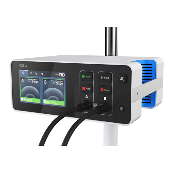
Front View Display/Touch Screen Hard Controls Start Start Stop Stop Channel A Channel B Figure 2. Front View of Control Unit Table 2. Control/Indicator/Connector Description Power Button: Turns the Control Unit ON and OFF� When the Control Unit is ON, a green LED illuminates� Press and hold the button for 3 seconds to turn the Control Unit OFF�... -
Page 9: Back View
Control/Indicator/Connector Description Start Start Ultrasound Channel: Stop Stop The Control Unit has two ports or channels for Connector Interface Cable connections� The channels are labeled A and B and can provide energy for up to two devices at the same time� Ultrasound Start Button: Start Starts energy transmission for a specific channel when pressed�... -
Page 10: Side View
Mounting Bracket: Secures Control Unit to infusion stand or EKOS CU 4�0 Cart� USB Port: Used by Boston Scientific authorized personnel to download data and event logs using only a USB memory stick� Equipotential Terminal: In the absence of adequate grounding on the A/C mains power line, this terminal can be connected to a locally available external equipotential line to prevent danger caused by the difference in the potentials between this device and other devices�... - Page 11 Menu Tabs AC Power/Battery Status Channel A Channel B Message Area Message Area Figure 5. Example Screen-Prior to Connection Table 4 Item Description Home Tab: Displays cable connection and system instructions, and ultrasound runtime� Information Tab: Displays Control Unit model number and software version, Connector Interface Cable and device information and the EKOS help line phone number Graph Tab: Displays a line graph that shows the percentage of the maximum average power delivered for...
-
Page 12: Screen Layout - During Ultrasound Therapy
Screen Layout – During Ultrasound Therapy During ultrasound therapy, the display/touch screen provides helpful information to monitor the ultrasound therapy� This information is provided for each channel independently and channels can be interacted with separately� The channels are labeled A and B and can provide energy for up to two devices at the same time�... -
Page 13: Color Coding Glossary
The Control Unit is designed to be operated by medical personnel who have knowledge of endovascular interventional procedures and who are responsible for direct patient care in the areas of the hospital where the unit is used� Optional in-service training from an authorized EKOS or Boston Scientific trainer is available� INTENDED USE The EKOS Control System 4�0 is intended to be used with EKOS Endovascular Devices to employ high frequency (2 MHz - 3 MHz), low power... -
Page 14: Warnings
Note: The following warning and precaution statements provide important information for safe operation of the Control Unit� Observe all warnings and precautions provided in these Instructions for Use� Failure to do so may result in patient injury, operator injury or product damage�... -
Page 15: Precautions
The Control Unit is designed to be operated by medical personnel who have knowledge of endovascular interventional procedures and who are responsible for direct patient care in the areas of the hospital where the unit is used� Optional in-service training from an authorized EKOS or Boston Scientific trainer is available� •... -
Page 16: Adverse Events
• When using two EKOS Devices (one in channel A and one in channel B), care should be taken to not cross the device cables� Ensure each pair of device cables is connected to a single Connector Interface Cable� If the device cables are crossed, ultrasound is not operational and could result in delay of ultrasound therapy�... -
Page 17: Electromagnetic Emissions Declarations
Electromagnetic Emissions Declarations Table 7. Guidance and manufacturer’s declaration – electromagnetic emissions The Control Unit is intended for use in the electromagnetic environment specified below� The customer or the user of the Control Unit should assure that it is used in such an environment� Emissions text Compliance Electromagnetic environment - guidance... - Page 18 Guidance and manufacturer’s declaration – electromagnetic immunity Power frequency 3 A/m 3 A/m Power frequency magnetic fields should be at levels (50/60 Hz) characteristic of a typical location in a typical commercial magnetic field or hospital environment� IEC 61000-4-8 NOTE: U is the a�c�...
-
Page 19: How Supplied
Table 9. Recommended separation distances between portable and mobile RF communication equipment and the Control Unit The Control Unit is intended for use in an electromagnetic environment in which radiated RF disturbances are controlled� The customer or the user of the Control Unit can help prevent electromagnetic interference by maintaining a minimum distance between portable and mobile RF communications equipment (transmitters) and the Control Unit as recommended below, according to the maximum output power of the communications equipment�... -
Page 20: Storing The Control Unit Within The Clinical Facility
Note: Carefully clean the connector ports� Do not use excessive amounts of cleaning fluids� See table below for example cleaning and disinfection products� Table 10. Solution Example Product Up to 90 % isopropyl alcohol Super Sani‐Cloth™ by PDI Healthcare 10 % solution of bleach and water Sani‐Cloth™ Bleach by PDI Healthcare 5�... -
Page 21: Expected Service Life
2 hours of operation when no therapy is running for at least two years of service� If you find the battery is discharging quickly, contact Boston Scientific to arrange a battery replacement� Note that battery maintenance may be needed every two years�... - Page 22 Figure 7. Settings Menu Screen Audible Alert Volume 1� To increase the volume, tap the right volume symbol until the desired volume is achieved� 2� To lower the volume, tap the left volume symbol until the desired volume is achieved� Note: The minimum setting reduces the volume but does not silence the tone�...
-
Page 23: Preparing For Ultrasound Use
Figure 9. Language Confirmation Screen Preparing for Ultrasound Use 1� Verify the Control Unit is securely attached to the recommended infusion stand, EKOS CU 4�0 Cart, or placed on a table near the patient� 2� Connect the Control Unit power cord to an appropriate hospital-grade outlet� Warning: Connect the Control Unit only to a properly grounded hospital-grade outlet using the specified power cord�... -
Page 24: Using Ac Power And Charging The Battery
Figure 11. Logo Screen (Starting) 4� Allow the Control Unit to warm up to operating temperature (see Specifications) with power on prior to starting ultrasound therapy� Power The Control Unit operates on AC power or its internal lithium-ion battery� The system can switch from battery to AC power or from AC power to battery while the Control Unit is turned ON�... - Page 25 Table 11. Item Description Connected to AC power and battery is charging� Connected to AC power and battery is fully charged� If the battery is defective the battery icon is red with an X� The battery charge level (shown in %) is displayed in the upper right corner of the display, next to the AC power / battery status indicator (see Figure 12)�...
-
Page 26: Battery Gauge
Battery Gauge When the Control Unit is turned ON and is powered by the battery, a battery gauge shows the level of battery charge� As battery charge decreases, the battery gauge shows the decrease in battery charge� The battery gauge with a red bar indicates a very low or fully depleted battery�... -
Page 27: Critically Low Battery
The red battery gauge with an X indicates the battery is defective� Even with a battery error, the Control Unit can continue to operate as long as it is connected to AC power� Do not attempt to open the Control Unit and change the battery� Contact your Boston Scientific representative for information on replacing the battery�... -
Page 28: Battery Charging Indicator - Control Unit Turned Off
Figure 15. Battery Error Message Battery Charging Indicator – Control Unit Turned Off When the Control Unit is turned OFF, a battery icon is illuminated on the front of the Control Unit to indicate the battery charging status (see Figure 16)� Start Start Charging... -
Page 29: Starting Ultrasound
Table 14. Control Unit Turned Off & AC Not Connected Indicator Description Blinking red (once every 10 seconds) indicates Control Unit is not connected to AC power and reminds to plug into AC power (Charge greater than 30 %�) (Blinking) Blinking red (once every 10 seconds) and an audible alert indicates Control Unit is not connected to AC, the battery has reached a low charge state, and reminds to plug into AC power immediately�... - Page 30 Figure 18. Connect Interface Cable Screen Note: If the Connector Interface Cable is already connected when the Control Unit is turned ON, the channel is automatically activated and a connect device cables message is displayed (see Figure 20)� Similarly, if the Connector Interface Cable is connected after the Control Unit is turned ON, the channel is automatically activated and a connect device cables message is displayed (see Figure 20)�...
- Page 31 After the Connector Interface Cable is connected to the Control Unit, a connect message displays indicating to connect the device connectors to the Connector Interface Cable (see Figure 20)� Figure 20. Connect Device Cables Screen 3� Connect the Ultrasonic Core to the Connector Interface Cable (see Figure 21)� 4�...
- Page 32 Figure 22. Connect Infusion Catheter Screen Figure 23. Connect Ultrasonic Core Screen Once the device is properly connected, a ready message displays indicating the Control Unit is ready (see Figure 24)� Figure 24. Ready Screen 5� Turn on the drug and coolant pumps, and set the specified flow rate per the physician’s orders and within the flow rates specified in the EKOS Device Instructions for Use�...
-
Page 33: Monitoring Ultrasound
Warning: Secure device cables and the Connector Interface Cable using standard practices to preserve the integrity of the device, minimize device movement at the insertion site, and prevent device dislodgement� If the Connector Interface Cable is dropped, it has sufficient weight to pull on the device and possibly dislodge it from where it has been inserted into the patient�... - Page 34 Figure 27. Two Channels with Ultrasound Running Screen 2� Monitor the runtime clock to determine how long the channel has delivered ultrasound therapy� The runtime is shown as Hours:Minutes:Seconds� Time segments not yet reached are dimmed� In the example below, ultrasound therapy has been running for 23 minutes and 47 seconds (see Figure 28)�...
-
Page 35: Transporting The Patient And Control Unit
Figure 29. Ultrasound Paused/Ready Screen 4� To restart the ultrasound, press the Start button on the Control Unit for the appropriate channel� The runtime will resume from Start the time at which it was stopped� If the Start button is not pressed within 5 minutes the start reminder activates� Transporting the Patient and Control Unit Warning: Always use the handle when carrying the Control Unit�... -
Page 36: Completing Ultrasound
Device should be safely disposed of in accordance with hospital, administrative, and/or local government policy� Completing Ultrasound Ultrasound therapy can be provided for an individual device on a single channel or two devices using both channels� Because each channel operates independently, ultrasound can be stopped and completed for one or both channels at any time� 1�... -
Page 37: Information To Brief The Patient
Figure 33. Logo Screen (Shutting Down) Precaution: After each use, the Control Unit should be plugged into a hospital-grade outlet to ensure the battery is recharged fully� Failure to plug in the AC power after use could result in the battery not being fully charged and delay of ultrasound therapy� 5�... -
Page 38: Troubleshooting
Table 15. Item Description Control Unit Serial number for Control Unit Software Version Version number for Software Indication of Channel A or B CIC Serial # Serial number for the Connector Interface Cable Ultrasound Serial # Serial number for the Ultrasonic Core Catheter Serial # Serial number for the Infusion Catheter Ultrasound Zone... - Page 39 Channel A Channel B Power Information Power Information Figure 36. Screen Layout-Power Graph Table 16. Item Description Channel label (A and B): • Green icon indicates ultrasound is ready to start or currently running� • Yellow icon indicates further steps are required to start the ultrasound� •...
-
Page 40: Example Power Graphs
Example Power Graphs The power graph screen (Figure 37) shows an example of what is displayed for two devices using two channels� One device is connected to channel A and one device is connected to channel B� Ultrasound therapy has been running for approximately 13�5 hours continuously for both devices and is currently on as indicated by the green channel icons and the 63 % and 67 % power levels�... -
Page 41: Troubleshooting
Figure 39. Example-Snapshot Power Graph Troubleshooting The Control Unit provides system errors, channel errors and channel messages to communicate status information� Descriptions of these errors/messages and troubleshooting steps are provided in this section� In rare circumstances, the Control Unit may present fault dialogs, reboot, fail to properly boot at power on, or fail to turn off as a result of software anomalies�... -
Page 42: Technical Support
Technical Support The telephone numbers listed below are not intended for the handling of medical emergencies� Boston Scientific provides assistance only for technical issues involving the operation of the EKOS Control System 4�0� Use this contact information for assistance in Control Unit problems where the Control Unit requires attention to prevent compromising patient or user well-being in future operations�... -
Page 43: Channel Errors
Message Error Possible Cause Troubleshooting Step Description Code Battery/charge E008 Control Unit may have 1� Ensure the power cord is firmly connected to the Control Unit and error (AC not been dropped and is not plugged into AC power OR if the Control Unit is plugged into a power connected)�... -
Page 44: Technical Support
Technical Support The telephone numbers listed below are not intended for the handling of medical emergencies� Boston Scientific provides assistance only for technical issues involving the operation of the EKOS Control System 4�0� Use this contact information for assistance in Control Unit problems where the Control Unit requires attention to prevent compromising patient or user well-being in future operations�... - Page 45 Table 20. Message Error Possible Cause Troubleshooting Step Description Code Check the E300 Poor connection of the 1� Disconnect the Infusion Catheter� catheter E309 Infusion Catheter� 2� Inspect for fluid or damage to the pins� connector� E310 Infusion Catheter 3� Dry the Infusion Catheter connector, if necessary�...
- Page 46 Message Error Possible Cause Troubleshooting Step Description Code Check the E302 Poor connection of the 1� Disconnect the Ultrasonic Core or leave disconnected� Ultrasound Ultrasonic Core� 2� Inspect for fluid or damage of the pins� connector� 3� Dry the Ultrasonic Core connector, if necessary� Ultrasonic Core 4�...
- Page 47 Message Error Possible Cause Troubleshooting Step Description Code Check the E306 Connector Interface 1� Ensure the Connector Interface Cable is securely connected to the Control Unit� Connector Cable is disconnected 2� If the error persists, disconnect and reconnect the CIC� Interface Cable from the Control Unit 3�...
-
Page 48: Channel Messages
Channel Messages A channel message is specific to a particular channel and indicates a task needs to be completed for the Control Unit to provide ultrasound therapy to that channel� The message may also ask the operator to confirm a particular action that was initiated by the operator� It does not indicate that an error or failure has occurred�... -
Page 49: Infusion Stand
INFUSION STAND Using an Infusion Stand or EKOS CU 4�0 Cart During use or storage, the Control Unit can be attached to the EKOS CU 4�0 Cart or an infusion stand that meets at least the minimum specifications� Alternatively, the Control Unit can be placed on a flat table or cart� Note: For more information on the EKOS Cart see the EKOS CU 4�0 Cart Instructions for Use�... -
Page 50: Attaching The Control Unit To An Infusion Stand
Attaching the Control Unit to an Infusion Stand Follow the mounting instructions below to ensure the Control Unit is securely attached to the infusion stand� 1� Select a position to attach the Control Unit on the infusion stand� Ensure: • The infusion pumps and Control Unit are positioned as low as practical on the pole�... -
Page 51: Symbols And Indicators
Figure 48. Secure SYMBOLS AND INDICATORS The following symbols and indicators appear in these instructions, on the Control Unit, or on its components (e�g�, Connector Interface Cable)� Table 22. Symbol Description Power Button: Turns the Control Unit ON and OFF� When the Control Unit is ON, a green LED illuminates� Press and hold the button for 3 seconds to turn the Control Unit OFF�... - Page 52 Symbol Description Channel A: Channel icon may be green, yellow, red, or black on the display/touchscreen� The label for the hard buttons is always gray� Channel B: Channel icon may be green, yellow, red, or black on the display/touchscreen� The label for the hard buttons is always gray�...
- Page 53 Symbol Description Disables channel when pressed� Disable button may be green, yellow or red� Displays the current runtime for the channel� Runtime is the length of time a device has delivered ultrasound therapy on a channel� Time is displayed in Hours:Minutes:Seconds� Ultrasound therapy is ON�...
-
Page 54: Specifications
WARRANTY For device warranty information, visit (www�bostonscientific�com/warranty)� EKOS and EkoSonic are trademarks of Boston Scientific Corporation or its affiliates� Sani-Cloth and Super Sani-Cloth are trademarks of Professional Disposables International, Inc� All other trademarks are the property of their respective owners�... - Page 55 Si experimenta alguna dificultad para acceder a las Instrucciones de uso por Internet o si prefiere recibir un ejemplar impreso, diríjase al Servicio de Atención al Cliente de Boston Scientific o al representante en su país� Se le enviará un ejemplar gratuito, que debería recibir en un plazo de siete días�...
- Page 56 Se tiver dificuldade em aceder às IDU online ou se preferir receber uma cópia em papel, contacte o Apoio ao cliente da Boston Scientific ou o seu representante nacional local� Ser-lhe-á enviada uma cópia sem qualquer custo, que deverá ser recebida no prazo de sete dias�...
- Page 57 Em caso de dificuldade para acessar as instruções de uso on-line ou preferir receber um exemplar impresso, entre em contato com o serviço de atendimento ao cliente da Boston Scientific ou com o representante no seu país� Você receberá um exemplar gratuito em até sete dias�...
- Page 58 NÁVOD NA POUŽITIE Návod na použitie k tomuto produktu v elektronickej podobe je k dispozícii na internete. Návod na použitie vo formáte Adobe Portable Document Format (PDF) nájdete na stránkach www�IFU-BSCI�com� Pripravte si štítok produktu, budete potrebovať informácie, ktoré sú v ňom uvedené. Ak máte problémy s prístupom k návodu na použitie online alebo by ste radšej uprednostnili kópiu vo vytlačenej podobe, obráťte sa na zákaznícky servis spoločnosti Boston Scientific alebo miestneho zástupcu vo vašej krajine. Vytlačenú kópiu vám zašleme bezplatne do siedmich dní. ИНСТРУКЦИИ ЗА УПОТРЕБА Инструкциите за употреба за този продукт се предоставят в електронен формат по интернет. Посетете www�IFU-BSCI�com, за да получите достъп до ИЗУ като Adobe Portable Document Format (PDF) файл, и се уверете, че етикетът на продукта е достъпен за справка. Ако имате затруднения при достъпа до инструкциите за употреба онлайн или предпочитате да получите хартиен екземпляр, моля, обърнете се към отдела за обслужване на клиенти на Boston Scientific или към лицето за контакт за вашата страна. Безплатно ще ви бъде изпратен такъв екземпляр, който би трябвало да пристигне при вас в рамките на седем дни. UPUTE ZA UPOTREBU Upute za upotrebu ovog proizvoda isporučene su u elektroničkom obliku putem interneta. Posjetite stranicu www�IFU-BSCI�com da biste pristupili Uputama za upotrebu u formatu Adobe Portable Document Format (PDF) i pripremite oznaku proizvoda za referencu�...
- Page 59 Jika Anda kesulitan mengakses IFU secara online, atau lebih suka menerima salinan cetak, silakan hubungi Layanan Pelanggan Boston Scientific atau kontak negara setempat Anda� Anda akan dikirimi satu salinan secara gratis dan salinan akan sampai di alamat Anda dalam tujuh hari�...
- Page 60 Catalog Number Electrostatic Sensitive Device Humidity limitation. Número de catálogo Dispositivo sensible a la electrostática Límites de humedad. Numéro de catalogue Dispositif sensible aux décharges Limitation d'humidité. Bestell-Nr. électrostatiques Luftfeuchtigkeitsbegrenzung. Numero di catalogo Elektrostatisch empfindliches Gerät Limiti di umidità. Catalogusnummer Dispositivo sensibile all'energia elettrostatica Vochtigheidsgrens.
- Page 61 Boston Scientific Corporation 300 Boston Scientific Way Marlborough, MA 01752 USA Customer Service +1-888-272-1001 www.bostonscientific.com Do not use if package is damaged. Recyclable Package 2797 © 2022 Boston Scientific Corporation or its affiliates� 2022-03 All rights reserved� 51011236-001 Black (K) ∆E ≤5.0...
Need help?
Do you have a question about the EKOS Control System 4.0 and is the answer not in the manual?
Questions and answers