Table of Contents
Advertisement
Quick Links
Advertisement
Table of Contents

Related Manuals for Vatech PaX-i Insight


Summary of Contents for Vatech PaX-i Insight
- Page 1 Installation Manual Model : PCH-30CS Version : 1.42 • English Full version...
- Page 3 The information contained in this manual may be subject to change without notice, justification, or notification of the persons concerned. VATECH Co., Ltd. (manufacturer) reserves intellectual property rights (IPR) for this manual and the equipment described herein. This IPR is protected by related laws and reproduction of this manual, in part or in full, is prohibited without the prior written consent of the Manufacturer.
- Page 4 Notice Manual Name: PaX-i Plus / Insight (Model: PCH-30CS) Installation Manual Document number: VDH-IM-070 Version: 1.42 Publication Date: 2022-07 PaX-i Plus / Insight (Model: PCH-30CS) Installation Manual...
- Page 5 Important Notes Important Notes Moisture could be built upon the equipment from a sudden temperature change inside and outside the installation room. Allow at least an hour before turning ON the equipment to avoid condensation. To avoid improperly balanced equipment, install the device on a ▪...
- Page 6 Important Notes This Page Intentionally Left Blank PaX-i Plus / Insight (Model: PCH-30CS) Installation Manual...
-
Page 7: Table Of Contents
Table of Contents Table of Contents Notice Important Notes Table of Contents Introduction Manufacturer's Liability ............... 1 Customer’s Responsibility ..............1 Conventions in this Manual ..............2 Marks and Symbols ................8 Choosing an Installation Site Room Requirements ................9 Specifications for Electrical Installation .......... - Page 8 Table of Contents Installing the CEPH Unit (Optional) ..........49 Fixing the Base (Optional) ..............52 Connecting the Cables to the Equipment.......... 55 Leveling the Equipment ..............57 4.10 Aligning the Ceph unit ............... 60 4.11 Tightening the Bolts ................64 Installing the Equipment: Wall Mount Installing the Equipment ..............
- Page 9 Table of Contents Installing Software Before Beginning ................93 Software Installation Flow ..............94 Installing Image Viewer Program ............. 94 Installing the InstallShield ..............95 Setting up the User Information ............. 107 Technical Specifications 10.1 Mechanical Specifications..............121 10.2 Environmental Specifications ............
- Page 10 Table of Contents This Page Intentionally Left Blank viii PaX-i Plus / Insight (Model: PCH-30CS) Installation Manual...
-
Page 11: Introduction
1. Introduction Introduction Manufacturer's Liability As the manufacturer, VATECH assumes liability for the safe and reliable installation and operation of this equipment only when: ▪ Equipment installation, including software installation, was carried out by an authorized agent by this installation manual. -
Page 12: Conventions In This Manual
1. Introduction Conventions in this Manual The following symbols are used throughout this manual to emphasize information or indicate a potential risk to the equipment or user. Make sure that you fully understand each symbol and follow the instructions accompanied. To prevent physical injury and/or damage to the equipment, please observe all warnings and safety information included in this document. - Page 13 1. Introduction Never touch or hold the Sensor or Tube Head areas while moving, installing, or operating the equipment. Do not use the electrical power drill during installation unless it can do so. Do not use the electrical power drill during installation unless it can do so.
- Page 14 1. Introduction The recommended holding area during transportation is as below. Three installers are required to install the equipment safely. The Main Power Switch and Emergency Stop Switch are located at the bottom of the Vertical Frame as below. PaX-i Plus / Insight (Model: PCH-30CS) Installation Manual...
- Page 15 Do not connect any items or equipment to this system which are not part of the system: IEC60601-1-1 (3 edition: 2005). ▪ Any equipment not approved by VATECH must comply with the applicable standards: IEC 60950-1 (2 edition: 2005) for IT equipment (Ex: PC) and IEC 60601-1 (3 edition: 2005) for medical electrical equipment.
- Page 16 1. Introduction Installation Site ▪ The PC monitor, emergency cut off switch, and X-ray Exposure Switch should be installed near the operator so that he or she can manage them simultaneously in an emergency. ▪ Proper shielding of the room is essential: Since these requirements vary depending on the country, it is the installer’s responsibility to verify that all applicable radiation safety requirements.
- Page 17 ▪ Any equipment not provided by VATECH can be connected when the following standards are complied with: IEC 60950-1 and IEC 60601-1 ▪ The electrical installation shall comply with local code requirements for electro-medical systems: IEC 60364-7- 710: 2002.
-
Page 18: Marks And Symbols
1. Introduction Marks and Symbols Symbols Description Location Power board / Dangerous voltage Inverter board / Monoblock Protective earth (Ground) Column Off (power: disconnected to the Main Power Main Power Switch) Switch On (power: connected to the Main Power Main Power Switch) Switch MCU board / Warns ESD hazard. -
Page 19: Choosing An Installation Site
2. Choosing an Installation Site Choosing an Installation Site Room Requirements The location of this equipment should allow for high ▪ visibility of the patient by the operator and the operator should be as near to the patient as possible. ▪... - Page 20 2. Choosing an Installation Site <With CEPH Unit (optional): 2,805 (L) x 2,233 mm (W) or wider > <Ceiling Height: 2,420 mm (H) or higher > PaX-i Plus / Insight (Model: PCH-30CS) Installation Manual...
- Page 21 2. Choosing an Installation Site Minimum Space Required Without CEPH unit 1,890 mm (L) x 2,233 mm (W) x 2,420 mm (H) With CEPH unit 2,805 mm (L) x 2,233 mm (W) x 2,420 mm (H) If the ceiling height is less than 2392 mm (without Base) / 2420 mm (with Base) (= max.
-
Page 22: Specifications For Electrical Installation
2. Choosing an Installation Site Specifications for Electrical Installation These specifications are based on the MEIGaN (Medical electrical installation guidance notes). Electrical Requirement This equipment must be connected to a grounded outlet to fulfill the safety provisions specified in IEC 60364: the 2 edition (2006). - Page 23 2. Choosing an Installation Site To assure line voltage quality, a separate 3-core ▪ grounded power cable connected directly to the central distribution panel with an over-current circuit breaker rated for 20A must be used. ▪ Maximally allowed deviation of the tube voltage/tube current/exposure time: Tube Voltage (kVp) ±...
-
Page 24: Environmental Specifications
2. Choosing an Installation Site Environmental Specifications Item Description 10 ~ 35 ℃ Temperature During Operation Relative humidity 30 ~ 75 % Atmospheric pressure 860 ~ 1060 hPa Temperature -10 ~ 60 ℃ During Transport Relative humidity 10 ~ 75 % and Storage Atmospheric pressure 860 ~ 1060 hPa... -
Page 25: Exposure Switch Installation Options
2. Choosing an Installation Site Exposure Switch Installation Options There are three options for installation, depending on the configuration of the site. Nevertheless, the 2 option is preferred. Option No. 1: The user operates the Exposure Switch from inside the X-ray room. Option No. - Page 26 2. Choosing an Installation Site Option No. 3: The 3 party Exposure Switch (not VATECH’s) is used on the demand of the customers. For this scenario, see Appendix D “Connecting the 3 party The Exposure Switch” for details. PaX-i Plus / Insight (Model: PCH-30CS) Installation Manual...
-
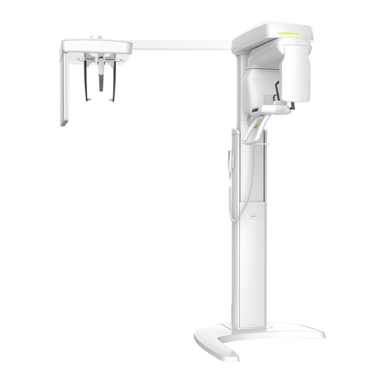
Page 27: Installation Versions
2. Choosing an Installation Site Installation Versions Base-stand Type PaX-i Plus / Insight (Model: PCH-30CS) Installation Manual... - Page 28 2. Choosing an Installation Site Wall-mount Type PaX-i Plus / Insight (Model: PCH-30CS) Installation Manual...
-
Page 29: Installing The Warning Lamp And Door Interlock Switch
2. Choosing an Installation Site Installing the Warning Lamp and Door Interlock Switch Refer to Appendix A for a complete installation guide. ▪ This system can be equipped with a warning lamp and the Door Interlock Switch which are activated when the X-ray is energized. ▪... -
Page 30: Before Installing The System
3. Before Installing the System Before Installing the System Before or during the system installation, make sure that you use the checklist No.3 through No.6 in the Appendix F. Installation Checklist. Required Tools The following tools are necessary to install the PaX-i Plus / Insight. Item Figure Size... - Page 31 3. Before Installing the System Item Figure Size Cross Head Screw Driver w/ Magnetic L = 200 mm (7.9”) Spirit Level Anti-Static Glove Knife Tape Ruler : for Wall Mount type Marker Pen (thick tip) : for Wall Mount type Hammer : for Wall Mount type Multimeter...
-
Page 32: Checking The Shockwatch And Tiltwatch Indicators
If either the packaging is damaged or the ShockWatch or TiltWatch indicators have been activated, please do not open the package and immediately contact the shipping company, agent, or VATECH. Shock Watch Tilt Watch PaX-i Plus / Insight (Model: PCH-30CS) Installation Manual... -
Page 33: Unpacking Boxes
Unpacking Boxes ▪ All packaging and Styrofoam used to ship this equipment are recyclable. ▪ Return the packaging to VATECH representatives or dispose of it in compliance with the legal regulations of your country. Box No. 1 - Main Box 3.3.1... - Page 34 3. Before Installing the System Removing the Cover Move the Main Box to a convenient place as close as possible to the installation location. Remove the Top Cover. Remove a single side cover. In case of unable to lift the side cover-up fully, due to ceiling height, cut the box in half using the utility knife instead.
- Page 35 3. Before Installing the System Put the PC System (Optional) down on the floor. Separate two side EPS (A, B). The resulting view is as follows. Do not discard these EPS (A, B), so that they are reused later when the CEPH unit is installed. Separate two side EPS (A, B).
- Page 36 3. Before Installing the System ⚫ The view after removal of the EPS is as below. PaX-i Plus / Insight (Model: PCH-30CS) Installation Manual...
- Page 37 3. Before Installing the System Box No. 2 - Base Unit 3.3.2 Component Size (mm / inch) Weight (kg / lbs.) 1046 (L) x 1056 (W) x 185 (H) / Base 47 / 103 41" (L) x 41.5" (W) x 7" (H) Removing the cover Open the box cover, the Base Cover appears.
- Page 38 3. Before Installing the System Remove the upper box, the Base Unit appears. PaX-i Plus / Insight (Model: PCH-30CS) Installation Manual...
- Page 39 3. Before Installing the System Box No. 3 – CEPH Unit (Optional) 3.3.3 Component Size (mm / inch) Weight (kg / lbs.) 1590(L) x 820(W) x 870(H) / CEPH unit 50 / 110 62.6"(L) x 32.3"(W) x 34.3"(H) Removing the cover Open the box cover and remove the packing material as shown in the figure.
-
Page 40: Checking The Parts
3. Before Installing the System Checking the Parts Location Layout of the Parts and Accessories 3.4.1 PaX-i Plus / Insight (Model: PCH-30CS) Installation Manual... - Page 41 3. Before Installing the System Parts List 3.4.2 In the Accessory Box 1 & 2 Part Confirmed Items Specification Figure Comments (OK?) User Manual Yes □ No □ Installation Manuals Yes □ No □ Manual 2D Viewer Yes □ No □ Manual Installation Yes □...
- Page 42 3. Before Installing the System Part Confirmed Items Specification Figure Comments (OK?) Temple Right & Left 1 set Yes □ No □ Supports Cap Ear Right & Left 1 set Yes □ No □ Rods Anti-Static 1 pair Yes □ No □ Gloves Chin Block ABS (WHITE)
- Page 43 3. Before Installing the System Part Confirmed Items Specification Figure Comments (OK?) Blank Silicon Cap White Yes □ No □ Base Cap 1 Yes □ No □ Base Cap 2 Yes □ No □ Blank Blank Cable Tie Yes □ No □ Optic Cable Yes □...
- Page 44 3. Before Installing the System Part Confirmed Items Specification Figure Comments (OK?) M10 x 25 Wrench Bolt w/ Spring and Yes □ No □ Flat Washers Wrench Bolt M10 x 25 Yes □ No □ M8 x 45 Wrench Bolt w/ Spring and Yes □...
- Page 45 3. Before Installing the System Part Confirmed Items Specification Figure Comments (OK?) Ficher strong M10 x 40 Yes □ No □ anchor EAM8N column M10-L20 Wrench Bolt w/ Spring Yes □ No □ Washer Ficher strong M8 x 30 Yes □ No □ anchor EAM8N wall...
-
Page 46: Installing The Equipment: Base Stand (Optional)
4. Installing the Equipment: Base Stand (Optional) Installing the Equipment: Base Stand (Optional) Unloading the Base and Main Unit First, unload the Main Unit on the floor. ▪ Place some protective stuff on the floor to avoid the scratches on the surface. ▪... - Page 47 4. Installing the Equipment: Base Stand (Optional) Put the Main Unit back on the master packing EPS and remove the protective plastic cover with a knife. Then put the cables down on the floor carefully. Be careful not to damage the cables or have the column surface scratched.
- Page 48 4. Installing the Equipment: Base Stand (Optional) Remove the carrying handle at the bottom of the column unit. Allen Wrench 6 mm / 0.24” PaX-i Plus / Insight (Model: PCH-30CS) Installation Manual...
-
Page 49: Assembling The Base With The Column Unit
4. Installing the Equipment: Base Stand (Optional) Assembling the Base with the Column Unit If the installation site is a concrete floor, go to section 4.5 Fixing the base (Optional) and do number 1 first, after that turn back 4.2 Assembling the Base with the Column Unit. Hang the base unit onto two bolts temporarily as shown below. - Page 50 4. Installing the Equipment: Base Stand (Optional) Fasten the Base Unit with two Wrench Bolts. Allen Wrench 8 mm / 0.3” M10 x 20 Wrench Bolt w/ Spring (Part No. 23) Put the bolts into the holes until about 20 mm are left outside.
- Page 51 4. Installing the Equipment: Base Stand (Optional) Put the equipment in a vertical position slowly while holding the upper handle. Be sure not to damage the cables. Before erecting the equipment, keep them clear of the equipment. Tighten the three Wrench Bolts to attach the base unit. Allen Wrench 8 mm / 0.31”...
-
Page 52: Removing The Transportation Handle (Without The Ceph Unit)
4. Installing the Equipment: Base Stand (Optional) Removing the Transportation Handle (without the CEPH unit) Remove the upper carrying handles. Allen Wrench 6 mm / 0.24” One installer should hold the handle, while the other is removing the bolts. PaX-i Plus / Insight (Model: PCH-30CS) Installation Manual... -
Page 53: Installing The Wall And Column Brackets
4. Installing the Equipment: Base Stand (Optional) Installing the Wall and Column Brackets Assembling the Column Bracket Remove the plastic wrap covering the column unit by using a cutter. Prepare the column bracket. Wall Bracket 2 (Part. No. 22) Attach the above bracket to the back of the column with the four Wrench Bolts. M8 x 20 w/ spring and Wrench Bolt... - Page 54 4. Installing the Equipment: Base Stand (Optional) Combining Column and Wall Brackets Prepare the wall bracket. Wall Bracket (Part No. 35) Combine the column and wall brackets in the following manner with the 2 Wrench Bolts. Allen Wrench 6 mm / 0.24” M8 x 25 w/ Spring and Flat Wrench Bolt...
- Page 55 4. Installing the Equipment: Base Stand (Optional) Marking Points on the Wall Move the equipment to the installation site as close as possible. Adjust the distance between the wall and equipment by moving it slightly, so that the wall bracket touches the wall. Mark four anchor bolt locations on the wall.
- Page 56 4. Installing the Equipment: Base Stand (Optional) Drilling on the Wall Drill the wall holes of size 10.5 mm x 30 mm (depth) using the concrete hammer drill. Remove the debris and clean the holes using the dust pump. Using the hammer, insert a Ficher strong anchor into the hole. Ficher Strong Anchor M8 x 30 Hammer...
- Page 57 4. Installing the Equipment: Base Stand (Optional) Combining the Equipment with the Anchor Bolts Place the equipment on the alignment plate, while observing 4 Hex bolts are being inserted properly through each hole. Hex Bolt M8 x 15 Spring Washer Flat Washer Torque Wrench Spanner type...
-
Page 58: Removing The Transportation Safety Bolts
4. Installing the Equipment: Base Stand (Optional) Removing the Transportation Safety Bolts Remove the semi-transparent tape on both sides of the vertical top cover. When removing the semi-transparent tape, be careful not to scratch the surface of the equipment. Remove the vertical top cover. Remove the safety lock bolt with a wrench. -
Page 59: Installing The Ceph Unit (Optional)
4. Installing the Equipment: Base Stand (Optional) Installing the CEPH Unit (Optional) Never hold the areas of the collimator, sensor, and tube head. Now it is assumed that the CEPH box has already been opened. Remove the plastic wrap covering the column unit and the tape for fixing the CEPH cables by using a cutter. - Page 60 4. Installing the Equipment: Base Stand (Optional) Tighten the four wrench bolts to attach the base unit. Allen Wrench 6 mm / 0.24” M8 x 45 w/ Spring and Wrench Bolt Flat Washers (Part No. 25) ▪ When fastening a bolt, make sure that the cable is not stuck on the surface.
- Page 61 4. Installing the Equipment: Base Stand (Optional) Connect H002010A of the CEPH unit to CN1202 of the MCU board. Connect the H002040A fiber optic cable to the CEPH port of the optic hub. When handling fiber optic cable, Do not bend, pull, and/or crushing it. Ensure that the caps of the fiber optic cable be removed Do not touch the tip of the fiber optic cable to prevent it from being dirty.
-
Page 62: Fixing The Base (Optional)
4. Installing the Equipment: Base Stand (Optional) Fixing the Base (Optional) Concrete Floor L = 200 mm (7.9”) Hammer Drill Hammer Ficher Strong M10 x 40 Anchor (Part No. 34) 8 mm / 0.3” Allen Wrench M10 x 25 Wrench Bolt w/ Spring and Flat Washers (Part No. - Page 63 4. Installing the Equipment: Base Stand (Optional) Secure the anchor bolts with the hammer. Place the base unit combined equipment in the proper position, lock the nuts and washers using a ratchet wrench. PaX-i Plus / Insight (Model: PCH-30CS) Installation Manual...
- Page 64 4. Installing the Equipment: Base Stand (Optional) Wooden Floor M12 x 70 Wood Screws (Part No. 34) L = 200 mm Hammer Drill (7.9”) Secure the base unit using the wood screws. PaX-i Plus / Insight (Model: PCH-30CS) Installation Manual...
-
Page 65: Connecting The Cables To The Equipment
4. Installing the Equipment: Base Stand (Optional) Connecting the Cables to the Equipment. Connect the cables in the back of the column as shown in the figure. Cable No. Optic Cable H002040A (Part No. 21) Cable Tie (Part No. 20) PaX-i Plus / Insight (Model: PCH-30CS) Installation Manual... - Page 66 4. Installing the Equipment: Base Stand (Optional) Use the Cable Tie (Part No. 20) or Cable Holder (Part No.20) to fix the cables as shown below after the connection is completed. PaX-i Plus / Insight (Model: PCH-30CS) Installation Manual...
-
Page 67: Leveling The Equipment
4. Installing the Equipment: Base Stand (Optional) Leveling the Equipment T-shaped Hex 8 mm / 0.3” Wench Spirit Level Ensure that the Spirit Level should rest only on the locations indicated in the following figures to obtain the accurate center. Prepare the Spirit Level. - Page 68 4. Installing the Equipment: Base Stand (Optional) Leveling Right and Left Place the Spirit Level, as shown in the figure. Adjust the base until the bubble on the Spirit Level centers in the middle, by turning left and right screws clockwise or vice versa. PaX-i Plus / Insight (Model: PCH-30CS) Installation Manual...
- Page 69 4. Installing the Equipment: Base Stand (Optional) Leveling the Front and Back Place the Spirit Level on the Vertical Frame, as shown in the following figure. Adjust the screws until the bubble of Spirit Level centers (level), by turning the front and/or back screws clockwise or vice versa.
-
Page 70: Aligning The Ceph Unit
4. Installing the Equipment: Base Stand (Optional) Aligning the Ceph unit 4.10 Allen Wench 8 mm / 0.3” Allen Wench 10 mm / 0.4" Spirit Level Ensure that the Spirit Level should rest only on the locations indicated in the following figures to obtain the accurate center. - Page 71 4. Installing the Equipment: Base Stand (Optional) When the Ceph unit is tilted to the right or left To adjust the Align bolt, untighten four Wrench Bolts (M8) slightly. Adjust the level of the Ceph unit on both the right and left sides until the bubble on the Spirit Level sensors in the middle, by adjusting Align Bolt (M10).
- Page 72 4. Installing the Equipment: Base Stand (Optional) When the aligning is completed, tighten four Wrench Bolts (M8) of the Main unit fully. When the Ceph unit is tilted to the front or back Untighten four Wrench Bolts (M8) of the Ceph unit slightly. Align the level of the Ceph on both the front and back sides unit until the bubble on the Spirit Level centers in the middle, by adjusting the Align Bolt (M10).
- Page 73 4. Installing the Equipment: Base Stand (Optional) When the aligning is completed, tighten four Wrench Bolts (M8) fully. PaX-i Plus / Insight (Model: PCH-30CS) Installation Manual...
-
Page 74: Tightening The Bolts
4. Installing the Equipment: Base Stand (Optional) Tightening the Bolts 4.11 Tighten the joint bracket bolts. Allen Wrench 6 mm / 0.24” Monkey Wrench PaX-i Plus / Insight (Model: PCH-30CS) Installation Manual... -
Page 75: Installing The Equipment: Wall Mount
5. Installing the Equipment: Wall Mount Installing the Equipment: Wall Mount Installing the Equipment You are advised to plan and study the installation environment carefully in advance before proceeding since the installation involves drilling the wall and floor. Pre- installation planning is crucial to a successful installation. Accurate marking is of critical importance for a successful installation. - Page 76 5. Installing the Equipment: Wall Mount Marking Points on the Floor Put the aligning plate on the floor near the wall where the equipment should be installed as shown in the figure. Alignment Plate (Part No. 4) Mark 6 anchor bolts holes on the floor. Marker PaX-i Plus / Insight (Model: PCH-30CS) Installation Manual...
- Page 77 5. Installing the Equipment: Wall Mount Drilling the Floor Remove the aligning plate. Drill the floor holes (size: 10.5 x 30 mm) by using the concrete hammer drill. Remove the debris and clean the holes with the dust pump. Put the Ficher strong anchor bolts into the holes and attach them with the hammer.
- Page 78 5. Installing the Equipment: Wall Mount Combining the Equipment with the Anchor Bolts Put the aligning plate on the floor while making sure that the align plate’s holes engage in the anchored bolts. Put the equipment in a vertical position slowly while holding the upper handle as shown in the figure.
- Page 79 5. Installing the Equipment: Wall Mount Put the Equipment on the aligning plate while making sure that the column bottom holes engage in the anchored bolts. Put the washers and nuts into the six anchored bolts on the floor and tighten the nuts loosely.
-
Page 80: Removing The Transportation Handle)
5. Installing the Equipment: Wall Mount Removing the Transportation Handle) (without the CEPH unit) Please refer to section 4.3 Installing the CEPH Unit (Optional). Installing the Wall and Column Brackets Please refer to section 4.4 Installing the Wall and Column Brackets. Removing the Transportation Safety Bolts Please refer to section 4.5 Removing the Transportation Safety Bolts. -
Page 81: Leveling The Equipment
5. Installing the Equipment: Wall Mount Leveling the Equipment T-shaped Hex 8 mm / 0.3” Wench Spirit Level Ensure that the Spirit Level should rest only on the locations indicated in the following figures to obtain the accurate center. Prepare the Spirit Level. Turn the Rotating Unit clockwise so that the X-ray tube head faces the front as shown in the figure. - Page 82 5. Installing the Equipment: Wall Mount Put the set screws into the four holes and turn them clockwise with the hex wrench until they touch the aligning plate. T-shaped Hex Wench 8 mm / 0.3” M10 x 20 Set Screw (Part No.
- Page 83 5. Installing the Equipment: Wall Mount Leveling the Front and Back Assemble the vertical top cover. Turn each set screw clockwise or counterclockwise to make the equipment level while another person monitors the level indicator. Assemble the column front case PaX-i Plus / Insight (Model: PCH-30CS) Installation Manual...
-
Page 84: Tightening The Bolts
5. Installing the Equipment: Wall Mount Tightening the Bolts Tighten the joint bracket bolts. Allen Wrench 6 mm / 0.24” Monkey Wrench Allen Wrench 8 mm / 0.3” Tighten the nuts in the anchored bolts on the floor. PaX-i Plus / Insight (Model: PCH-30CS) Installation Manual... -
Page 85: Completing Miscellaneous Works
6. Completing Miscellaneous Works Completing Miscellaneous Works Assembling Base Cover (Optional) When removing the semi-transparent tape, be careful not to scratch the surface of the equipment. Assemble the base cover. Base Cover Fix the base cover with 3 truss bolts. M5 x 8 Truss Bolt (Part No. - Page 86 6. Completing Miscellaneous Works Cover the holes. (Cap1: 3, Cap2: 6) Base Caps 1 (Part No. 17) Base Caps 2 (Part No. 17) PaX-i Plus / Insight (Model: PCH-30CS) Installation Manual...
-
Page 87: Assembling The Temple Supports And The Chinrest
6. Completing Miscellaneous Works Assembling the Temple Supports and the Chinrest Assembling the Temple Supports and the Bite Block should be done after Acquiring a test image is completed Insert the normal Chinrest and the normal Bite Block into the unit. Chin Block-High (Part No.7) Chin Bite... -
Page 88: Installing The Switch Holders
6. Completing Miscellaneous Works Installing the Switch Holders Up / Down (Part No. 2) Switch Holder Up / Down Optional Switch (Part No. 2) Exposure (Part No. 2) Switch Holder Double-Sided (Part No. 2) Sticker M3X16 Screws (Part No. 2) Up / Down Switch Holder Peel out the papers on the double-sided sticker. -
Page 89: Setting Up Pc
7. Setting up PC Setting up PC Direct Connection Diagram Fiber Optic Cable - Used to transfer image data to the PC. Warning System Panel - Used to provide a visible indicator: Light on when the equipment is irradiating X-ray. PaX-i Plus / Insight (Model: PCH-30CS) Installation Manual... -
Page 90: The Recommended Pc Requirements
7. Setting up PC The Recommended PC Requirements ▪ It is mandatory to ensure that the PC system configuration is compatible with the PC system requirements for the imaging and image viewer software. ▪ Since image quality may be deteriorated from lack of resources, observe the requirement guideline specified in the following tables. - Page 91 7. Setting up PC ◼ PaX-i Insight Item Specifications Intel Core i5-7500 3.4 2133 4C CPU Chipset Intel C236 Chipset 16GB DDR4-2400 nECC (2X8GB) Unbuffered RAM Hard disk drive 1TB SATA 7200 1st HDD Graphic board NVIDIA GTX 1050Ti ®...
- Page 92 7. Setting up PC Disabling Windows Defender Open the Start screen, type Windows Defender in the search box. Click the Windows Defender icon to start Windows Defender on the search result. Click the Settings icon. On the Settings window, click Add an exclusion in the Exclusions section. On Select Folder window, type C:\VcaptureSW in the folder field and click Exclude this folder.
-
Page 93: Installing The Internal Peripherals
7. Setting up PC Installing the Internal Peripherals Allow enough time to dissipate remnant energy after unplugging the power cord from the main outlet or PC. ▪ Disregard this section in case the PC system is supplied with the equipment. (The peripherals have already been installed inside the PC.) ▪... - Page 94 7. Setting up PC Installing the Fiber Optic Frame Grabber Board Unplug the power cable from the back of t h e PC and wait for a while. Open the PC cover. Insert the fiber grabber board (Part No. 21) carefully into that PCIe2 x 4 slot and lock it.
-
Page 95: Connecting The Cables To Pc
7. Setting up PC Connecting the Cables to PC ▪ Always check the cable condition visually. Surprisingly, unexpected errors affecting image acquisition arise from the bad cable or its bad contact condition. ▪ Connect the regular cables for PC: keyboard, mouse, and video in advance. - Page 96 7. Setting up PC Confirm the result after connections are as same as below. The illustrations may differ from the actual product. PaX-i Plus / Insight (Model: PCH-30CS) Installation Manual...
-
Page 97: Setting Up Pc's Environment Variables
8. Setting up PC’s Environment Variables Setting up PC’s Environment Variables Disregard this section in case the PC system is supplied with the equipment. (The environment variables of the PC have already been set on the PC.) Before Beginning ▪ Ensure that the Emergency Stop Switch is in the OFF position before starting with the InstallShield installation. -
Page 98: Turning Off The Firewall
8. Setting up PC’s Environment Variables Turning off the Firewall The LAN port and/or local IP may be blocked by the Windows Firewall property, leading to interruptions in imaging acquisition and data transmission. For this reason, it is required to disable the Windows Firewall by using the following procedures. Open the Start screen, type Windows Firewall in the search box. -
Page 99: Setting Up The Power Management Options
8. Setting up PC’s Environment Variables Setting up the Power Management Options To avoid disruptive and abnormal operation while acquiring an image, it is required to reconfigure some parameters on the Windows operating system. Disable the Screen Saver Open the Start screen, type Screen Saver in the search box. On-Screen Saver Settings screen, select (None) in the pull-down menu. - Page 100 8. Setting up PC’s Environment Variables Selecting the Power Options: Monitor and System Open the Start screen, type Power Options in the search box. Click Choose when to turn off the display. Select Never for both Turn off the display and Put the computer to sleep fields. Click Save changes to apply the settings.
-
Page 101: Turning Off The User Account Control
8. Setting up PC’s Environment Variables Turning off the User Account Control Open the Start screen, type User Account Control in the search box. Disable the UAC by moving the slider bar down to the bottom, Never notify. Then, click OK to apply change settings. PaX-i Plus / Insight (Model: PCH-30CS) Installation Manual... -
Page 102: Setting Folder Exclusions With Anti-Virus Software
For the PaX-i Plus / Insight, the following folders and files inside for relevant software should be excluded from the virus scan. Path Software C:\Program Files\Vatech EzDent-i C:\VCaptureSW Console Software ▪... -
Page 103: Installing Software
9. Installing Software Installing Software Disregard this section in case the PC system is supplied with the equipment. (The software has already been installed.) Before Beginning ▪ Ensure that the Emergency Stop Switch is in the OFF position before starting with the InstallShield installation. -
Page 104: Software Installation Flow
9. Installing Software Software Installation Flow Installing Image Viewer Program One of the image viewer programs among EzDent-i or 3 party program must be installed at this time. For the details on the installation procedures, refer to the corresponding manuals. PaX-i Plus / Insight (Model: PCH-30CS) Installation Manual... -
Page 105: Installing The Installshield
9. Installing Software Installing the InstallShield The InstallShield installation information is included in the USB drive provided as an accessory. Please check the serial number.txt (eg 047-011752.txt) file. Turn on the PC and the equipment if they are not yet. Insert the CD into the CD-ROM drive or connect the USB drive to the USB connector and then perform a virus scan for the PC before installing the CD. - Page 106 9. Installing Software Check the equipment model (PaX-i Plus_Insight) and click Next Make sure that all modalities are checked as the following. If the equipment does not include the CEPH feature, uncheck the CEPH option, and then click Next. PaX-i Plus / Insight (Model: PCH-30CS) Installation Manual...
- Page 107 9. Installing Software Make sure that “I2Pano or WidePano” is selected in the Pano sensor type selection window and then click Next. (Optional) Confirm that the “WideCeph” is selected in the CEPH sensor type selection window and click Next. Select COM2 for the default port number and click Next. PaX-i Plus / Insight (Model: PCH-30CS) Installation Manual...
- Page 108 9. Installing Software 10. Select the language and click Next. 11. Select the 3 party software in use and click Next. when EzDent-i is installed, select SDK. Then, click Next to continue. 12. Check the options according to the product specifications. When the AutoSave is checked, the image data acquired saved automatically.
- Page 109 9. Installing Software 14. Confirm that the following drivers are selected. For the first-time installation, select all. 15. You can check the information entered so far with the Ready to Install window. If necessary, you can modify it by clicking Back. 16.
- Page 110 9. Installing Software Installing the DirectX InstallShield will continue to DirectX® installation process. Select “I accept the agreement” in the Welcome window. PaX-i Plus / Insight (Model: PCH-30CS) Installation Manual...
- Page 111 9. Installing Software Click Next to start the installation. PaX-i Plus / Insight (Model: PCH-30CS) Installation Manual...
- Page 112 9. Installing Software Click Finish to exit the wizard. PaX-i Plus / Insight (Model: PCH-30CS) Installation Manual...
- Page 113 9. Installing Software Installing the Frame Grabber (Virtual Serial 1.x) <Flectron Grabber> After completing the Direct X® installation, Grabber Driver Setup will be started. Select the language in the installer language window and press the OK button. When the Grabber Driver Setup window appears, click the Next button. Enter the installation location and click the Install button.
- Page 114 9. Installing Software The "Installing" window will appear and disappear, and the Completing Grabber Driver Setup window will appear. Choose the Reboot now or I want to reboot later and click the button manually. If an error occurs during installation, it will be displayed in red font color below.
- Page 115 9. Installing Software <V.Grabber-OCS > 1) After completing the Direct X® installation, the installation program will be started. Select the language in the installer language select window and press the OK button. 2) Press the V.Grabber’s Install button. 3) The installation is completed and the V.Grabber Installation Program window appears.
- Page 116 9. Installing Software Finishing Installation The installation has just been completed. Click Finish and restart PC. Verifying that All Components are Properly Installed Locate the file: PaX-i Plus_Insight_Install_Log.txt on the desktop. Open it to check the file. You can find out that all components are installed. Go to section 9.5 Setting up the User Information.
-
Page 117: Setting Up The User Information
9. Installing Software Setting up the User Information Go to the corresponding section for set-up instructions, based on the viewer program (EzDent-i (SDK)) installed on EzDent-i: Refer to section 9.5.1 when EzDent-i is installed. The automatic interworking function is activated only when using the Console program with automatic interworking function and EzDent-i program. - Page 118 9. Installing Software Click the Compatibility tab, select Run this program as an administrator in the Settings section and click OK to apply the settings. (In case there are multiple log-in users to the computer and it needs to apply the settings to all users on the computer, utilize Change settings for all users button.
- Page 119 9. Installing Software Setting EzDent-i 9.5.1 Setting the Imaging Acquisition Options Start EzDent-i on your PC. Click Main Menu, then select Settings. In setting widow, click Acquisition. PaX-i Plus / Insight (Model: PCH-30CS) Installation Manual...
- Page 120 9. Installing Software In the Acquisition tab, click Console Program. In the Console Program tab, check: whether “Sync capture setting with console program” is selected Console software path Patient information fire path Display acquisition button. Click OK and restart the computer to apply the new setting. PaX-i Plus / Insight (Model: PCH-30CS) Installation Manual...
- Page 121 9. Installing Software Creating a New Patient Information For the features not explained in this section, go to the EzDent-i user manual. Click the Add Patient from the PATIENT tab. Enter the required fields (*) in the patient information: Chart number ...
- Page 122 9. Installing Software Initiating the Imaging Program Click the Acquisition tab. The imaging mode selection menu appears in the left pane (see below). The imaging mode selection menu may differ due to your equipment’s option (CEPH or non-CEPH) or the Display option you selected in the setting menu.
- Page 123 From the main GUI window, click the settings icon in the upper right corner. Log in the tap will be open by default. On the right side of the screen, select Engineer and type the password ('vatech') and then click Log In. Click the User tab.
- Page 124 9. Installing Software Select Use Label in the Image Label Options section. When selected, the character string in the Label Text field is displayed. By default, the equipment model name is displayed. Set the DAP (Dose Area Product) Level and DAP Unit for the unit which is displayed on the screen.
- Page 125 9. Installing Software In the Patient Information Setting, configure Link Type and File Path as shown below. In the Database & Linking, configure Link Type and File Extension as follows. Fields When EzDent-i is used CT / CR Link SDK Link Type CR Save Name PaX-i Plus / Insight (Model: PCH-30CS) Installation Manual...
- Page 126 9. Installing Software 10. Click the Default Set tab and configure the user-defined parameters. The default feature can be modified, according to the user’s requirement. 11. Click Save if changes occurred. PaX-i Plus / Insight (Model: PCH-30CS) Installation Manual...
- Page 127 9. Installing Software Disabling the Packing Mode Unless the packing mode is disabled, the equipment will not operate even after it is turned on. PaX-i Plus_Insight has a unique feature─ packing mode─ built into the system to prevent the unit from being damaged while shipping and transporting.
- Page 128 9. Installing Software Enter the command PKEN_0000] to exit the packing mode. Now note that the equipment is out of the packing mode. Click the Exit button and terminate the control panel. Exit the imaging program and restart the equipment to take the changes into effect.
- Page 129 9. Installing Software Selecting an Announcement Mode (Optional) When selecting an announcement between music and beep arises, take the following procedures. Commands specifications: Command format: [SPM_MPOP_XXXX] Announcement XXXX Imaging Modes Division Mode 0000 PANO/CEPH Music Different for each mode 0001 PANO/CEPH Music The same for each mode...
- Page 130 9. Installing Software Finalizing the Console Software Settings Click the Exit → Close button and terminate the control panel. (Important!) Exit the imaging program (main GUI) and restart the equipment to take the changes into effect. PaX-i Plus / Insight (Model: PCH-30CS) Installation Manual...
-
Page 131: 10. Technical Specifications
10. Technical Specifications 10. Technical Specifications Mechanical Specifications. 10.1 Dimensions (unit = mm) With CEPH Unit Without CEPH Unit With Base Without Base PaX-i Plus / Insight (Model: PCH-30CS) Installation Manual... - Page 132 10. Technical Specifications Item Description 95 kg (209.4 lbs. – without Base) Without CEPH unit 135 kg (297.6 lbs. – with Base) Weight 120 kg (264.5 lbs. - without Base) With CEPH unit 160 kg (352.7 lbs. - with Base) Without Base Max.
-
Page 133: Environmental Specifications
10.3 PANO Option Reconstruction Time Insight PAN Approximately 1 minute Reconstruction time exists for PaX-I Insight only. ⚫ The above data is obtained from a computer system which is based on HP ⚫ Z440 and GeForce GTX1060 6GB Image reconstruction time varies depending on computer specifications ⚫... -
Page 134: Appendix
Appendix Appendix A. Installing the Warning Lamp and Door Interlock Switch Requirement The warning control system shall be connected to the ERB (earth reference bar) of the room that it is associated with. The switching arrangements, location, height, and several illuminated warning signs shall be agreed with the local radiation protection advisor (RPA). - Page 135 Appendix Schematic Diagram Components Supplied Procedures <The individual cable length:> Signal Cable: 5m/198” ⚫ Door interlock cable: 5m/198” ⚫ Warning lamp: 1m/40” ⚫ Power source cable: 1m/40” ⚫ PaX-i Plus / Insight (Model: PCH-30CS) Installation Manual...
- Page 136 Appendix Prepare the Warning System Panel (Part No. 28) Install the Warning System Panel at the proper height after taking each cable length into account. Connect the warning lamp (not provided). Connect the door interlock switch (not provided). Connect the power source for the warning lamp. PaX-i Plus / Insight (Model: PCH-30CS) Installation Manual...
-
Page 137: Installing The Emergency Stop Switch
Appendix B. Installing the Emergency Stop Switch Install the Emergency Stop Switch on the power cable line. ⚫ Install this switch so that it is easy to reach in the emergency case but can’t ⚫ be pushed by mistake. The switch shall be a type of mistake-proof. ⚫... -
Page 138: Limiting The Column Height
Appendix C. Limiting the Column Height This section explains how to limit the column height within the permissible range. Measure the ceiling height in the X-ray shield room: H ceiling < Removing the column covers > Remove three Fixing Bolts as shown in the figure. Remove the Column Rear-Top Cover as shown in the figure. - Page 139 Appendix Remove the side cover. PaX-i Plus / Insight (Model: PCH-30CS) Installation Manual...
- Page 140 Appendix Determining the Height Calculate the adjustment bolt position by using the following formula. -d, where d is the minimum distance, 30 cm (12") between the screw height ceiling ceiling and the top of the equipment (when the equipment is fully loaded). (e.g.
- Page 141 Appendix Adjusting the Screw Height We know the H is 220 mm from the previous example. So, we will move the screw height screw from the default (current) position to the new one. Loosen two bolts halfway (important!). Do not unscrew completely the bolt. If not, it could drop into the column and may cause big trouble to retrieve it out.
-
Page 142: Connecting The 3 Rd Party Exposure Switch (Optional)
D. Connecting the 3 party Exposure Switch (Optional) This section explains how to connect the third-party Exposure Switch with the equipment from VATECH. < How to > Cut the Exposure Switch cable provided with the equipment. According to the following schematic diagram, rewire the cables. -
Page 143: Checking Pc Bios Settings
Appendix E. Checking PC BIOS Settings < HP PC BIOS Setup > PC Model: HP Z440 PC BIOS default Main Menu Sub1 Menu Sub2 Menu Setup Value Advanced Power Options Runtime Power Management [Disable] Advanced Power Options Idle Power Savings [Normal] Advanced Power Options... -
Page 144: Installation Checklist
Appendix F. Installation Checklist 1. General Information: Customer Information about the Equipment Purchaser Name of Clinic or Hospital Address Phone E-Mail Website Dealer Information about the Equipment Seller Name of Dealer Address Phone E-Mail Website PaX-i Plus / Insight (Model: PCH-30CS) Installation Manual... - Page 145 Appendix 2. Installation Information: Address of Installation Site Names of Installers Scheduled Date of Installation Date of installation Model Serial No. 3. System Delivery to Site: Did you review and identify the delivery route and method for equipment in advance? Is the freight elevator available? Is the security guard, if any, notified of the installation in advance?
- Page 146 Appendix 4. Before Installation: Site Check List Is the room large enough? At minimum, with CEPH unit: 2,805 mm (L) x mm 2,233 (W) x 2,420 mm (H) / 111” x 88” x 96” Without CEPH unit: 1,890 mm (L) x 2,233 mm (W) x 2,420 mm (H) / 75”...
- Page 147 Appendix After Opening Boxes Did the installers make sure there are not any scratches or broken surface equipment? Are all accessories and cases included in the box? Have you read the installation manual out in its entirety before starting the installation? Did the installer take pictures after opening the boxes? Did the installer make sure there are not any suspicious holes or scratches on the box after opening?
- Page 148 Type: Is the 3 party software installed? If yes, indicate the name(s) and versions. Are they compatible with software from Vatech®? If No, Version: indicate the name(s) and versions. 8. Electrical Requirements: Is the circuit breaker installed and tested in the distribution...
- Page 149 Appendix 9. Network Configuration: Is the network configured with 1 Gbit/s of CAT5? Is the equipment connected to the network? Is the network installation company identified? What is the TCP/IP address assigned? Address: What is the subnet masking address? Address: Is there a DHCP server? PaX-i Plus / Insight (Model: PCH-30CS) Installation Manual...
- Page 151 No part of this manual may be reproduced, transmitted, or transcribed without the expressed written permission of the manufacturer. We reserve the right to make any alterations that may be required due to technical improvement. For the most current information, contact your VATECH representative. Tel: (+82) 1588-9510 Email: gcs@vatech.co.kr Website: www.vatech.com...
- Page 152 설치 설명서 Postal Code: 18449 13, Samsung 1-ro 2-gil, Hwaseong-si, Gyeonggi-do, Korea www.vatech.com...
Need help?
Do you have a question about the PaX-i Insight and is the answer not in the manual?
Questions and answers