Table of Contents
Advertisement
Quick Links
Advertisement
Table of Contents

Related Manuals for Vatech Premium PAX-i3D


Summary of Contents for Vatech Premium PAX-i3D
- Page 2 PCT-90LH User Manual...
-
Page 3: Notice
Due to constant technological improvement, the manual may not contain the most updated information and is subject to change without prior notice to the persons concerned. For further information not covered in this manual, please contact us at: VATECH Co., Ltd. Phone: +82-1588-9510 E-mail: gcs@vatech.co.kr This document is originally written in English. -
Page 4: Table Of Contents
Table of Contents Notice ........................ v Table of Contents ..................... vi Introduction ..................1 Overview ..................1 Indications for use ................1 Intended purposes ................1 Intended User Profile................ 2 General Information................3 Manufacturer's Liability ..............3 Owner and Operator's Obligations ............. 3 Conventions in this Manual ............... - Page 5 Getting Prepared for Patient Positioning ........... 62 Patient Positioning ................64 X-ray Exposure ................78 Checking the captured image ............80 Acquiring i-CEPH Images (Optional) ..........81 i-CEPH Imaging Program Overview ..........81 Configuring Exposure Parameters ............ 83 Getting Prepared for Patient Positioning ........... 86 Patient Positioning ................
- Page 6 15.4 Environmental Specifications ............159 Appendices ..................161 16.1 Recommended X-ray Exposure Table ..........161 16.2 X-ray Dose Data ................166 16.3 Electromagnetic Compatibility (EMC) Information ......175 16.4 Hand-wrist Image Evaluation References ........180 16.5 Acquiring Images for Pediatric Dental Patients ........184 16.6 Abbreviations ................195 viii PaX-i3D Green Premium™...
-
Page 7: Introduction
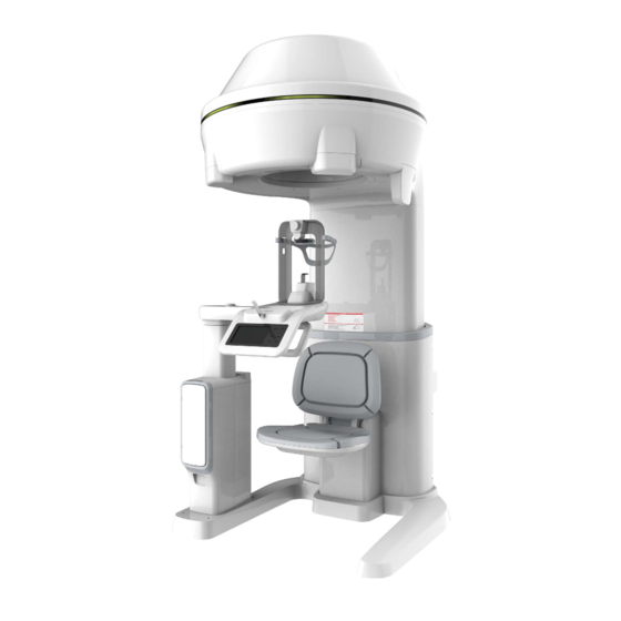
1. Introduction Introduction Overview PaX-i3D Green Premium™ (Model: PCT-90LH) is an advanced 4 in 1 digital X-ray imaging system that incorporates PANO, i-CEPH (Optional), 3D CT (Dental / ENT) and 3D PHOTO (Optional) imaging capabilities into a single system for Dental and ENT (Ear, Nose and Throat) diagnostics. -
Page 8: Intended User Profile
1. Introduction - Planning any craniofacial surgery where 3D models of the jaw/facial skeleton/skull are required - Diagnosis of most malformations and dysplasia, traumatic lesions and thin osseous labyrinthine wall erosion or dehiscence through CBCT inner ear imaging - Visualization of eustachian tube obstruction - Reconstruction of position, malformations and fractures of nasal and facial bones and paranasal sinuses as 3D pictures for operational planning and patient education - Air-mucosa-bone contrast for detailed study of air cavity anatomy and ventilation... -
Page 9: General Information
The equipment has been installed in accordance with all of the cautions and conditions required for installation. The genuine VATECH approved equipment and components have been used at all times. All maintenance and repairs have been performed by a VATECH-authorized ... -
Page 10: Conventions In This Manual
2. General Information Conventions in this Manual The following symbols are used throughout this manual. Make sure that you fully understand each symbol and follow the instructions accompanied. To prevent physical injury and/or damage to the equipment, please observe all warnings and safety information included in this document. -
Page 11: Marks And Symbols
2. General Information Marks and Symbols Symbols Description Location Power Dangerous voltage board board / Warns ESD hazard. Board package Protective earth (Ground) Column Main Off (power: disconnected to the Main Power Power Switch) Switch Main On (power: connected to the Main Power Power Switch) Switch... - Page 12 2. General Information Symbols Description Location Indicates that electrical and electronic equipment must not be disposed of as Label unsorted municipal waste and must be collected separately. Indicates that this equipment is classified as a CLASS 1 LASER Label PRODUCT in accordance with IEC 60825-1 ED.2 regulations.
- Page 13 2. General Information 2.4.1 Label Locations Item PaX-i3D Green Premium™ (Model: PCT-90LH) Main Label X-ray GENERATOR Label - This part has two types according to the X-ray Tube model implemented. * Type 1: Superior tube (SXR-130-15-0.5) * Type 2: C.E.I tube (OX/115-05) CLASS 1 LASER PRODUCT Label PCT-90LH User Manual...
- Page 14 2. General Information Item X-ray CAUTION Label - X-ray / Attention: X-ray on when equipment in operation. Wheelchair Height Limit CAUTION Label - In case a wheelchair must be used, the overall height of the wheelchair must not exceed the designated line. PaX-i3D Green Premium™...
-
Page 15: Warnings And Precautions
3. Warnings and Precautions Warnings and Precautions Be sure to strictly observe all warnings and safety instructions included in this manual. This X-ray unit may be dangerous to patients and operators unless safe exposure factors, operating instructions and maintenance schedules are observed. General Safety Guidelines Operator qualifications This equipment may only be operated by personnel fully trained in its operation. - Page 16 If this product is exposed to water, moisture, or a foreign substance, immediately turn off main power of the equipment and contact your VATECH technical support representative. If there are signs of oil leakage, immediately cease all operations of this ...
- Page 17 3. Warnings and Precautions Hygiene Always disconnect the equipment from the power outlet when disinfecting the surfaces of the equipment. Never expose this equipment to liquids, mists or sprays. Exposing this equipment to liquids may cause an electric shock or otherwise damage the system.
- Page 18 No part of this equipment is serviceable by the operator. All maintenance and repair of this equipment must be performed by a VATECH qualified service technician. This product may only be operated with original VATECH accessories or third- ...
-
Page 19: Electricity-Related Safety Precautions
3. Warnings and Precautions Electricity-related Safety Precautions To avoid risk of electric shock, this equipment must only be connected to supply mains with protective earth. Check the status of the power source, PC and cables prior to operating the equipment. - Page 20 3. Warnings and Precautions Static Discharge Connector pins or sockets bearing ESD warning labels must not be touched or interconnected without observing ESD protective measures. Electrostatic discharge (ESD) ESD protective measures include Procedures for preventing electrostatic charge build-up (e.g. temperature control, ...
-
Page 21: Radiation Safety
3. Warnings and Precautions Radiation Safety Since rules and regulations concerning radiation safety differ between countries, it is the responsibility of the owner and/or operator of this equipment to comply with all applicable rules and regulations concerning radiation safety and protection in their area. This equipment must be housed inside an X-ray shielded room. -
Page 22: Warnings
3. Warnings and Precautions Warnings The following warning statements should be obeyed with the utmost care. Failure to follow these warnings may cause severe damage to the equipment or physical injuries to the patient and/or the operator. X-ray equipment is hazardous to patient and the operator if proper ... - Page 23 The use of accessories and cables other than those specified, with the exception of cables sold by VATECH of the medical electrical equipment or medical electrical system as replacement parts for internal components, may result in increased EMISSIONS or decreased IMMUNITY of EQUIPMENT or SYSTEM.
- Page 24 3. Warnings and Precautions In case of electrical fire Use only fire extinguishers designed for electrical fires to extinguish fires on this equipment. (Liquid extinguishers, such as those which use water, could damage the equipment and/or cause physical injury.) Unplug the equipment’s power cable before extinguishing any fire.
-
Page 25: Imaging System Overview
4. Imaging System Overview Imaging System Overview System Components PaX-i3D Green Premium™ digital X-ray equipment PC system Console Software: PANO, i-CEPH (Optional), Dental CT, ENT CT and 3D PHOTO EzDent-i: 2D viewer and patient management software Ez3D-i: 3D viewer and image analysis software ... -
Page 26: Standards And Regulations
4. Imaging System Overview Auto Ceph option is available under DENTAL CT (FOV: 21x19) and ENT CT (FOV: 21x19) modality. * When selected, Auto Pano and/or Auto Ceph image is automatically acquired and can be seen on the Viewer. EzDent-i Standards and Regulations Standards PaX-i3D Green Premium™... -
Page 27: Imaging System Configuration
4. Imaging System Overview Imaging System Configuration PCT-90LH User Manual... - Page 28 4. Imaging System Overview PC Signal Input / Output Item USB Camera input (USB 3.0 Cable) To avoid any connection problem, it is highly recommended to install a USB 3.0 PCI card for USB 3.0 cables. 3D Viewer License Key Video output Fiber optic cable (Data in / out) Ethernet cable (LCD in / out)
-
Page 29: Equipment Overview
4. Imaging System Overview Equipment Overview PCT-90LH User Manual... - Page 30 4. Imaging System Overview Item Description Displays the status of X-ray exposure. - Green: Ready LED Lamp - Yellow: X-ray ON LED Lamps provide enough light for 3D LED lights (TOP) & Photography. Eye marks (#2,#3) Eye marks help to position the patient' head correctly when taking a 3D photograph.
- Page 31 4. Imaging System Overview Item Description Chinrest Adjusts the height of the Chinrest. Up/Down Switch PCT-90LH User Manual...
- Page 32 4. Imaging System Overview 4.5.1 Control Panel Buttons Description Configures the parameter settings in each imaging mode. For more information, refer to 4.5.2 Touch Touch Screen Screen. Laser Beam ON/OFF Turns on/off the vertical Laser Beam. button Indicates that imaging is ready after parameter settings READY button and the patient positioning are complete.
- Page 33 4. Imaging System Overview 4.5.2 Touch Screen Set options for imaging of each mode by using Touch Screen. It provides the same function as the PC's Console Software. Touch Screen and Console Software (5.3. Console Software) are interlocked mutually therefore indicate the same environment setting values always.
- Page 34 4. Imaging System Overview PANO Main Screen Function Description Displays available PANO Examination programs. Examination mode (In PANO – Orthogonal mode, press UP/DOWN button selection panel to scroll through next/previous ROI option) NEXT button Moves to the next step. Moves back to the modality (PANO, i-CEPH (Optional), BACK button Dental CT, ENT CT and 3D PHOTO (Optional)) selection screen.
- Page 35 4. Imaging System Overview PANO Settings Screen Function Description kVp/mA Adjusts kVp and mA. control button Patient’s gender Selects patient's gender / age group. / age group Selects X-ray intensity. Depending on the circumference of the patient’s X-ray intensity head, X-ray intensity may be classified as Hard, Normal, or Soft : Soft ≤...
- Page 36 4. Imaging System Overview i-CEPH Main Screen Function Description Examination Displays available i-CEPH Examination programs. selection panel NEXT button Moves to the next step. Moves back to the modality (PANO, i-CEPH (Optional), BACK button Dental CT, ENT CT and 3D PHOTO (Optional)) selection screen.
- Page 37 4. Imaging System Overview i-CEPH Settings Screen Function Description kVp/mA Adjusts kVp and mA. control button Patient’s gender Selects patient's gender / age group. / age group Selects X-ray intensity. Depending on the circumference of the patient’s X-ray intensity head, X-ray intensity may be classified as Hard, Normal, or Soft : Soft ≤...
- Page 38 4. Imaging System Overview CT (Dental / ENT) Main Screen Function Description FOV selection panel Displays available FOV modes. Moves to the next step. NEXT button Moves back to the modality (PANO, i-CEPH (Optional), BACK button Dental CT, ENT CT and 3D PHOTO (Optional)) selection screen.
- Page 39 4. Imaging System Overview CT (Dental / ENT) Settings Screen Function Description kVp/mA Adjusts kVp and mA. control button Patient’s gender / age Selects patient's gender / age group. group Selects X-ray intensity. Depending on the circumference of the patient’s X-ray intensity head, X-ray intensity may be classified as Hard, Normal, or Soft :...
- Page 40 4. Imaging System Overview 3D PHOTO Main Screen Function Description TOP LED light Press UP/DOWN button to adjust brightness of the LED Brightness control lights on the top. panel BOTTOM LED light Press UP/DOWN button to adjust brightness of the LED Brightness control light on the bottom.
- Page 41 4. Imaging System Overview 4.5.3 Emergency Stop Switch During operation, the following emergency situations may occur: X-ray emission even after the Exposure Switch has been released Physical injury to the patient or damage to the equipment Other emergency situations ...
- Page 42 4. Imaging System Overview 4.5.4 Exposure Switch The Exposure Switch allows the operator to control image acquisition from outside of the X-ray room. Press and hold the Exposure Switch down until acquisition is complete. Premature release of the Exposure Switch will abort image acquisition. Pressing the Exposure Switch activates the LED indicator to turn yellow.
- Page 43 4. Imaging System Overview 4.5.5 Enclosed Components The enclosed components can be disassembled and cleaned. All enclosed components that are used to support the patient (the Bite Block, the Chinrest and the Headrest) should be cleaned with ethanol and wiped with clean towels. Components Name and Function Contact (duration)
- Page 44 4. Imaging System Overview Left blank intentionally PaX-i3D Green Premium™ User Manual...
-
Page 45: Imaging Software Overview
5. Imaging Software Overview Imaging Software Overview Three programs are included in this equipment to acquire, process, and view the image: EzDent-i: 2D viewer and patient management Ez3D-i: 3D viewer Console software: PANO, i-CEPH (Optional), Dental CT, ENT CT and 3D ... -
Page 46: Pc Specifications (Recommended)
5. Imaging Software Overview PC Specifications (Recommended) The PC system plays an important role in image processing and verification. Configure the PC environment to meet the following specifications. If the PC specifications are not met, the image quality can be lower. Do not place patients near the equipment and PC. -
Page 47: Ezdent-I
5. Imaging Software Overview EzDent-i EzDent-i is dental imaging software from VATECH Co., Ltd. that manages patient images to make faster and more accurate diagnoses. EzDent-i, linked with the console software and 3D viewer, makes it convenient for the operator to use and process necessary images. -
Page 48: Console Software
5. Imaging Software Overview Console Software Use the Console Software to configure the imaging environment according to the mode. You can set the imaging parameters on either the Touch Screen or the Console Software running on the PC. They are synched and display the same environmental settings. - Page 49 5. Imaging Software Overview Item Description Imaging Mode Displays the current imaging mode. Display Scanning Status and Shows image acquisition progression and displays preview of Image the images acquired. Preview window Patient Information Displays information on the selected patient. window Guide Message Displays various text instructions for the operator.
- Page 50 5. Imaging Software Overview Item Description Moves to the next step. (Exposure parameter setting > Patient positioning > Ready for NEXT / exposure) READY button Activated when you click NEXT button after the patient positioning is completed. Click the button when all aspects of preparation are completed for image acquisition.
- Page 51 5. Imaging Software Overview Item Description 4. Press and hold down the Exposure Switch. Reconstructs the image manually when automatic image reconstruction fails: Manual Reconstructi Select a Modality after clicking this button. > Click Search on button button. > Select an image to reconstruct. > Click Reconstruction button.
- Page 52 5. Imaging Software Overview Left blank intentionally PaX-i3D Green Premium™ User Manual...
-
Page 53: Getting Started
6. Getting Started Getting Started Turning on the Equipment Do not place the patient close to the equipment when it’s be turned on. Doing so may cause physical injury to the patient and damage to the equipment. Do not operate the PC while the equipment is in operation. Doing ... -
Page 54: Running The Image Viewer (Ezdent-I)
6. Getting Started Running the Image Viewer (EzDent-i) The Imaging Program is interfaced with EzDent-i and the user can analyze the image acquired from the Console Software easily and rapidly. On your desktop, double-click EzDent-i icon. The EzDent-i main window will be displayed. For further details on this subject, refer to the EzDent-i User Manual. - Page 55 6. Getting Started 6.2.1 Creating a New Patient Record To create a new patient record, follow the procedure outline below: Click the Add Patient icon from the main GUI window. Enter the required patient information. Chart Number, E-Mail address, First Name, and Last Name are required fields which must be filled in.
- Page 56 6. Getting Started − Search by Name: Search by the name of the patient is possible. − Search by Gender / Age group can be used to divide the search results further, for patients with the same name. The user’s Login/Logout time and work duration can be traced via ...
-
Page 57: Initiating The Console Software
6. Getting Started Initiating the Console Software For a new patient, the patient information needs to be registered first. Search and select the patient to be captured. Click ACQUISITION tab and select the imaging mode (CT, Panorama, or Cephalo). The Main Screen for the selected mode appears. (Refer to 4.3 Console Software) From the Main Screen, you can configure the imaging parameter settings prior to acquiring an image. - Page 58 6. Getting Started Left blank intentionally PaX-i3D Green Premium™ User Manual...
-
Page 59: Acquiring Pano Images
7. Acquiring PANO Images Acquiring PANO Images PANO Imaging Program Overview Result Images It provides conventional 2D panoramic images. Image Acquisition Method It reconstructs U-shaped arch data to a single 2D image utilizing multiple images taken with the X-ray beam scanning specific oral & maxillofacial regions at different angles. Examination Programs It is classified as below based on the ROI (Region of Interest). - Page 60 7. Acquiring PANO Images Examination Arch Selection Example Type Bitewing Left* TMJ LAT Open TMJ LAT Close SPECIAL Examination Sinus LAT Sinus PA * Bitewing imaging mode is activated only when Orthogonal is selected in Arch Selection. PaX-i3D Green Premium™ User Manual...
- Page 61 7. Acquiring PANO Images Imaging Main Programs Examination Arch Description & Sample Image Type Selection A panoramic imaging mode for patients with a V-shaped arch trajectory. (Typically for some females) Narrow Standard A panoramic imaging mode for adult patients with a normal arch trajectory.
- Page 62 7. Acquiring PANO Images Examination Arch Description & Sample Image Type Selection A panoramic imaging mode to minimize the overlapped region of the teeth from the X-ray exposure which is beamed perpendicularly between teeth. Standard A panoramic imaging mode to acquire an image only for the region of interest through the orthogonal trajectory.
- Page 63 7. Acquiring PANO Images Examination Arch Description & Sample Image Type Selection An imaging mode to acquire a lateral image of the TMJ, in which the X-ray beam is directed on the lateral TMJ region. (TMJ Open and Close) TMJ LAT Open/Close A special imaging mode to acquire a Sinus image, in which X-ray beam is...
-
Page 64: Configuring Exposure Parameters
7. Acquiring PANO Images Configuring Exposure Parameters To acquire PANO Images, 6. Getting Started must be completed first. If not, you must return to the 6. Getting Started and finish the step first. You can set the imaging parameters either on the Touch Screen or through the Console Software running on the PC. - Page 65 7. Acquiring PANO Images “i-CEPH” and “3D PHOTO” buttons exist only when each imaging program is included in the equipment. Select a PANO Option. (On Touch Screen, click Settings button before selecting options.) <Console Software> <Touch Screen> Mode Description Normal Normal option Reconstructs the image with optimized focus Magic PAN...
- Page 66 7. Acquiring PANO Images For more information about Arch type, refer to 7.1.2 Main Imaging Program. Select an Examination Program. <Console Software> <Touch Screen> To activate three Bitewing examination options- Bitewing, Bitewing Right and Bitewing Left, select Orthogonal Arch in the Arch Selection panel.
- Page 67 7. Acquiring PANO Images Select X-ray intensity. <Console Software> <Touch Screen> Depending on the circumference of the patient’s head, X-ray intensity may be classified as Hard, Normal, or Soft : Soft ≤ Normal ≤ Hard The values of tube voltage and current are configured automatically according to the patient's gender / age group and X-ray intensity.
-
Page 68: Getting Prepared For Patient Positioning
7. Acquiring PANO Images Getting Prepared for Patient Positioning Have patients (especially pregnant women and children) wear a lead apron to protect themselves from residual radiation. Be careful not to direct the Laser Beam into the patient's eyes. Doing so may result in a permanent loss of vision. - Page 69 7. Acquiring PANO Images Getting prepared Let the patient remove all the metal objects (glasses, earrings, hair pins, braces, false teeth, etc.). Metal objects may induce ghost images and lower the image quality. Let the patient wear a lead apron to protect themselves from residual radiation. Push the Handle Frame’s Open/Close button inward and open the Handle Frame.
-
Page 70: Patient Positioning
7. Acquiring PANO Images Patient Positioning PANO Standard and Bitewing mode 7.4.1 For Normal patients Let the patient hold the handle in comfortable posture and see front. Patients need to keep the following poses during imaging process. Sit close against the chair. ... - Page 71 7. Acquiring PANO Images Insert the Bite Block into the Chinrest and cover it with a sanitary vinyl cover. The sanitary vinyl cover is for single use only. It should be replaced for each patient. Be sure to use the approved vinyl cover. ...
- Page 72 7. Acquiring PANO Images The vertical Laser Beam will be activated to make patient positioning easier. The DAP (Dose Area Product), Scan Time and Exposure Time will be displayed below Patient Information window. You can see the patient through the Touch Screen. Make sure that the horizontal lines displayed in the screen are parallel to the ...
- Page 73 7. Acquiring PANO Images Press READY button. No X-ray will be emitted at this point. <Console Software> <Touch Screen> Go to 7.5 X-ray Exposure to start the exposure. PCT-90LH User Manual...
- Page 74 7. Acquiring PANO Images For Edentulous Patients Let the patient hold the handle in comfortable posture and see front. Patients need to keep the following poses during imaging process. Sit close against the chair. Hold the handle. See front. ...
- Page 75 7. Acquiring PANO Images Insert the Sinus / Edentulous Bite into the Chinrest. Clean the Chinrest and the Bite Block with ethanol and wipe with a dry towel before the next patient. On the Console Software, Click NEXT button when the exposure parameter setting is completed.
- Page 76 7. Acquiring PANO Images You can see the patient through the Touch Screen. Make sure that the horizontal lines displayed in the screen are parallel to the patient’s Frankfurt line by using the Chinrest UP/DOWN button. Let the patient smile and make sure that the patient's canine teeth are positioned ...
- Page 77 7. Acquiring PANO Images 7.4.2 TMJ Mode Steps for TMJ Mode Patient’s positioning for TMJ Open > X-ray Exposure > Patient’s positioning for TMJ Close > X-ray Exposure TMJ Open mode Let the patient hold the handle in comfortable posture and see front. Patients need to keep the following poses during imaging process.
- Page 78 7. Acquiring PANO Images Insert the TMJ Bite into the Chinrest. Clean the Chinrest and the Bite Block with ethanol and wipe with a dry towel before the next patient. Let the patient place the base of their nose (acanthion point) against the Chinrest and bend the head forward about 5˚.
- Page 79 7. Acquiring PANO Images When you click NEXT (OK in Touch Screen) button, The Rotating Unit will come down to the positioning location. The vertical Laser Beam will be activated to make patient positioning easier. The DAP (Dose Area Product), Scan Time and Exposure Time will be displayed below Patient Information window.
- Page 80 7. Acquiring PANO Images TMJ Close mode The TMJ Close image can be acquired after the TMJ Open image is acquired. "Do you want to capture a TMJ Close image?" message will appear when the TMJ Open mode is completed. Press/Click OK button to begin TMJ Close mode. <Console Software>...
- Page 81 7. Acquiring PANO Images 7.4.3 Sinus Mode Let the patient hold the handle in comfortable posture and see front. Patients need to keep the following poses during imaging process. Sit close against the chair. Hold the handle. See front. ...
- Page 82 7. Acquiring PANO Images Let the patient bend the head backward around 10˚-15˚. Be careful the patient does not to touch the equipment with their jaw. Doing so may cause difficulty to maintain the proper position to get images of good quality. Align the Vertical Beam to the center of the patient's face.
- Page 83 7. Acquiring PANO Images Let the patient maintain the posture as follows: Close the mouth. Place the tongue to the roof of the mouth. Close the eyes. Before conduct the next step, be sure to let the patient know that the Rotating Unit will be lower to the exposure location and instruct him or her to relax down.
-
Page 84: X-Ray Exposure
7. Acquiring PANO Images X-ray Exposure If an emergency occurs during image acquisition, release the Exposure Switch to cease X-ray emission. The operator shall observe the X-ray safety regulations applicable to their area at all times during the operation of this equipment. During image acquisition (X-ray exposure), don’t use the Chinrest ... - Page 85 7. Acquiring PANO Images During X-ray exposure, the status appears as follows. The Green LED lights of the Exposure Switch and Rotating Unit turn yellow. An alert sound comes out to indicate that X-ray emission is currently underway. The X-ray Indicator icon of the Console Software turns yellow.
-
Page 86: Checking The Captured Image
7. Acquiring PANO Images Checking the captured image Acquired images can be reconstructed and converted to DICOM format. The exported images can be confirmed in EzDent-i. Refer to the EzDent-i User Manual for more information. The images are transferred to EzDent-i automatically. The images are automatically saved if automatic save option is configured as default. -
Page 87: Acquiring I-Ceph Images (Optional)
8. Acquiring i-CEPH Images (Optional) Acquiring i-CEPH Images (Optional) i-CEPH Imaging Program Overview Result Images It provides 2D images similar to conventional cephalometric images. Image Acquisition Method It reconstructs specific oral & maxillofacial regions to a single 2D image utilizing the data acquired through CT imaging method.. - Page 88 8. Acquiring i-CEPH Images (Optional) Examination Description Position Area Used to study the base of the skull, horizontal angulation of the mandibular condylar axis, the sphenoidal sinus, the curvature of the lower jaw, the side wall of the maxillary sinus, and zygomatic arch fractures.
-
Page 89: Configuring Exposure Parameters
8. Acquiring i-CEPH Images (Optional) Configuring Exposure Parameters To acquire i-CEPH images, 6. Getting Started must be completed first. You can set the imaging parameters on either the Touch Screen or the Console Software running on the PC. They are synched and display the same environmental settings. - Page 90 8. Acquiring i-CEPH Images (Optional) Select an i-CEPH Examination. <Console Software> <Touch Screen> For more information about i-CEPH examination, refer to 7.1 i-CEPH Imaging Program. The gender / age group of the patient is selected automatically based on the patient information.
- Page 91 8. Acquiring i-CEPH Images (Optional) Depending on the circumference of the patient’s head, X-ray intensity may be classified as Hard, Normal, or Soft : Soft ≤ Normal ≤ Hard The values of tube voltage and current are configured automatically according to the patient's gender / age group and X-ray intensity.
-
Page 92: Getting Prepared For Patient Positioning
8. Acquiring i-CEPH Images (Optional) Getting Prepared for Patient Positioning Have patients (especially pregnant women and children) wear a lead apron to protect themselves from residual radiation. Be careful not to direct the Laser Beam into the patient's eyes. ... - Page 93 8. Acquiring i-CEPH Images (Optional) Getting prepared Let the patient remove all the metal objects (glasses, earrings, hair pins, braces, false teeth, etc.). Metal objects may induce ghost images and lower the image quality. Let the patient wear a lead apron to protect themselves from residual radiation. Push the Handle Frame’s Open/Close button inward and open the Handle Frame.
-
Page 94: Patient Positioning
8. Acquiring i-CEPH Images (Optional) Patient Positioning Lateral, PA, SMV and Waters’ view Let the patient hold the handle in comfortable posture and see front. Patients need to keep the following poses during imaging process. Sit close against the chair. ... - Page 95 8. Acquiring i-CEPH Images (Optional) Put the Headrest Strap on the patient’s head and turn the knob clockwise to hold the head tightly. Remove the Chinrest from the unit. On the Console Software, Click NEXT button when the exposure parameter setting is completed.
- Page 96 8. Acquiring i-CEPH Images (Optional) You can see the patient through the Touch Screen. Make sure that the horizontal lines displayed in the screen are parallel to the patient’s Frankfurt line by using the Chinrest UP/DOWN button. Let the patient maintain the posture as follows: Close the mouth.
- Page 97 8. Acquiring i-CEPH Images (Optional) Carpus Make sure that the patient's upper arm is aligned with the Carpus Guideline engraved on the bottom surface of the Rotating Unit as shown below. If necessary, adjust the height by using the Rotating Unit UP/DOWN button on the Control Panel. Let the patient put the right hand splaying on the inner side of the Rotating Unit as shown below.
- Page 98 8. Acquiring i-CEPH Images (Optional) Click NEXT button when the patient positioning is completed. Then, READY button will be activated on the Touch Screen and the Console Software. Press READY button. No X-ray will be emitted at this point. <Console Software> <Touch Screen>...
-
Page 99: X-Ray Exposure
8. Acquiring i-CEPH Images (Optional) X-ray Exposure If an emergency occurs during image acquisition, release the Exposure Switch to cease X-ray emission. The operator shall observe the X-ray safety regulations applicable to their area at all times during the operation of this equipment. During image acquisition (X-ray exposure), don’t use the Chinrest ... - Page 100 8. Acquiring i-CEPH Images (Optional) During X-ray exposure, the status appears as follows. The Green LED lights of the Exposure Switch and Rotating Unit : [In Lateral, PA, SMV and Waters’ view modes ] become flashing for 6 seconds and turn yellow. : [In Carpus mode] turn yellow without flashing.
-
Page 101: Checking The Captured Image
8. Acquiring i-CEPH Images (Optional) Checking the captured image Acquired images can be reconstructed and converted to DICOM format. The exported images can be confirmed in EzDent-i. Refer to the EzDent-i User Manual for more information. The images are transferred to EzDent-i automatically. The images are automatically saved if automatic save option is configured as default. - Page 102 8. Acquiring i-CEPH Images (Optional) Left blank intentionally PaX-i3D Green Premium™ User Manual...
-
Page 103: Acquiring Dental Ct Images
9. Acquiring Dental CT Images Acquiring Dental CT Images Dental CT Imaging Program Overview Result Images It provides conventional 3D CT sliced images Image Acquisition Method It acquires images with the X-ray beam scanning specific oral & maxillofacial regions and reconstructs them to 3D sliced images. - Page 104 9. Acquiring Dental CT Images FOV (cm) Description Special Mode Dental CT + 3D PHOTO : 3D PHOTO images can be acquired as well as Dental CT images at one time. Special Option Auto Pano / Auto Ceph : 2D images of conventional panoramic / cephalometric view are available with the specific FOVs.
-
Page 105: Configuring Exposure Parameters
9. Acquiring Dental CT Images Configuring Exposure Parameters To acquire Dental CT Images, 6. Getting Started must be completed first. You can set the imaging parameters on either the Touch Screen or the Console Software running on the PC. They are synched and display the same environmental settings. - Page 106 9. Acquiring Dental CT Images <Touch Screen> “i-CEPH” and “3D PHOTO” buttons exist only when each imaging program is included in the equipment. To acquire 3D PHOTO with CT images, click DENTAL CT > CT+3D PHOTO button. Select FOV size. ...
- Page 107 9. Acquiring Dental CT Images You can configure the Auto Pano options when 17x15 is selected. (On the Touch Screen, press button to close Auto Pano / Auto Ceph option window.) <Console Software> <Touch Screen> You can configure Horizontal options when 8x8 is selected. <Console Software>...
- Page 108 9. Acquiring Dental CT Images for Standard mode in DICOM or BMP format.) ** Auto Ceph Auto Ceph is a feature used to acquire reconstructed 2D images during 3D CT scans without additional X-ray exposure. It has the same region that conventional cephalometric images offer. (It provides images for PA, Lateral, SMV and Waters’...
- Page 109 9. Acquiring Dental CT Images Select a Voxel Size. <Console Software> <Touch Screen> The gender / age group of the patient is selected automatically based on the patient information. If necessary, you can select the option manually. <Console Software> <Touch Screen> Select X-ray intensity.
- Page 110 9. Acquiring Dental CT Images The values of tube voltage and current are configured automatically according to the patient's gender / age group and X-ray intensity. Click Arrow button to zoom in. The dose is adjustable by the ±1 kVp and ±0.1 mA respectively. When the exposure parameter setting is completed, guide the patient to the equipment for positioning the patient.
-
Page 111: Getting Prepared For Patient Positioning
9. Acquiring Dental CT Images Getting Prepared for Patient Positioning Have patients (especially pregnant women and children) wear a lead apron to protect themselves from residual radiation. Be careful not to direct the Laser Beam into the patient's eyes. ... - Page 112 9. Acquiring Dental CT Images Getting prepared Let the patient remove all the metal objects (glasses, earrings, hair pins, braces, false teeth, etc.). Metal objects may induce ghost images and lower the image quality. Let the patient to wear a lead apron to protect themselves from residual radiation. Push the Handle Frame’s Open/Close button inward and open the Handle Frame.
-
Page 113: Patient Positioning
9. Acquiring Dental CT Images Patient Positioning 9.4.1 Dental CT mode Patient Positioning Let the patient hold the handle in comfortable posture and see front. Patients need to keep the following poses during imaging process. Sit close against the chair. ... - Page 114 9. Acquiring Dental CT Images Install the Headrest. (Only when Auto Ceph option selected.) Put the Headrest into the Chinrest. ① Put the Headrest Strap on the patient’s head and turn the knob clockwise to hold ② the head tightly. It is not mandatory to install the Headrest for CT mode.
- Page 115 9. Acquiring Dental CT Images Let the patient maintain the posture as follows: Close the mouth. Place the tongue to the roof of the mouth. Close the eyes. Before conduct the next step, be sure to let the patient know that the Rotating Unit will be lower to the exposure location and instruct him or her to relax down.
- Page 116 9. Acquiring Dental CT Images 9.4.2 Dental CT + 3D PHOTO mode Patient Positioning Let the patient hold the handle in comfortable posture and see front. Patients need to keep the following poses during imaging process. Sit close against the chair. ...
- Page 117 9. Acquiring Dental CT Images Remove the Chinrest from the unit. You can see the patient through the Image Preview Window or Touch Screen. Make sure that the horizontal lines displayed in the screen are parallel to the patient’s nasal base If necessary, click or press LED light UP/DOWN button to adjust LED light ...
- Page 118 9. Acquiring Dental CT Images Let the patient see the Eye mark #3 when you hear the beep sound. Put the Chinrest into the unit when 3D photography is completed. Click/Press NEXT button to continue with Dental CT Imaging. For more information, refer to 9.4.1 Dental CT mode (No.3 ~ No.10).
-
Page 119: X-Ray Exposure
9. Acquiring Dental CT Images X-ray Exposure If an emergency occurs during image acquisition, release the Exposure Switch to cease X-ray emission. The operator shall observe the X-ray safety regulations applicable to their area at all times during the operation of this equipment. During image acquisition (X-ray exposure), don’t use the Chinrest ... - Page 120 9. Acquiring Dental CT Images During X-ray exposure, the status appears as follows. The Green LED lights of the Exposure Switch and Rotating Unit become flashing for 6 seconds and turn yellow. An alert sound comes out to indicate that X-ray emission is ...
-
Page 121: Checking The Captured Image
9. Acquiring Dental CT Images Checking the captured image Acquired images can be reconstructed and converted to DICOM format. The exported images can be confirmed in EzDent-i. Refer to the EzDent-i User Manual for more information. The images are transferred to EzDent-i automatically. The images are automatically saved if automatic save option is configured as default. - Page 122 9. Acquiring Dental CT Images Left blank intentionally PaX-i3D Green Premium™ User Manual...
-
Page 123: 10. Acquiring Ent Ct Images
10. Acquiring ENT CT Images 10. Acquiring ENT CT Images 10.1 ENT CT Imaging Program Overview Result Images It provides conventional 3D CT sliced images. Image Acquisition Method It acquires images with the X-ray beam scanning specific oral & maxillofacial regions and reconstructs them to 3D sliced images. - Page 124 10. Acquiring ENT CT Images Special Mode ENT CT + 3D PHOTO : 3D PHOTO images can be acquired as well as ENT CT images at one time. Special Option Auto Pano / Auto Ceph : 2D images of conventional panoramic / cephalometric view are available with the specific FOV.
-
Page 125: Configuring Exposure Parameters
10. Acquiring ENT CT Images 10.2 Configuring Exposure Parameters To acquire ENT CT Images, 6. Getting Started must be completed first. You can set the imaging parameters on either the Touch Screen or the Console Software running on the PC. They are synched and display the same environmental settings. - Page 126 10. Acquiring ENT CT Images <Touch Screen> “i-CEPH” and “3D PHOTO” buttons exist only when each imaging program is included in the equipment. To acquire 3D PHOTO with ENT CT images, click ENT CT > CT+3D PHOTO button. Select FOV size.
- Page 127 10. Acquiring ENT CT Images * Auto Pano Auto Pano is a feature used to acquire reconstructed 2D images during 3D CT scans without additional X-ray exposure. It has the same region that conventional panoramic images offer. (It provides images for Standard mode in DICOM or BMP format.) * * Auto Ceph Auto Ceph is a feature used to acquire reconstructed 2D images...
- Page 128 10. Acquiring ENT CT Images The Green mode produces approximately 20 % ~ 40 % lower DAP value than the High Resolution mode during X-ray exposure. Mode Exposure Condition (mGy·cm FOV: 21x19 (cm) 2010 (108 kVp / 6.5 mA / 18.0 sec) High Resolution FOV: 17x11 (cm)
- Page 129 10. Acquiring ENT CT Images Select X-ray intensity. <Console Software> <Touch Screen> Depending on the circumference of the patient’s head, X-ray intensity may be classified as Hard, Normal, or Soft : Soft ≤ Normal ≤ Hard The values of tube voltage and current are configured automatically according to the patient's gender / age group and X-ray intensity.
-
Page 130: Getting Prepared For Patient Positioning
10. Acquiring ENT CT Images 10.3 Getting Prepared for Patient Positioning Have patients (especially pregnant women and children) wear a lead apron to protect themselves from residual radiation. Be careful not to direct the Laser Beam into the patient's eyes. ... - Page 131 10. Acquiring ENT CT Images Getting prepared Let the patient remove all the metal objects (glasses, earrings, hair pins, braces, false teeth, etc.). Metal objects may induce ghost images and lower the image quality. Let the patient wear a lead apron to protect themselves from residual radiation. Push the Handle Frame’s Open/Close button inward and open the Handle Frame.
-
Page 132: Patient Positioning
10. Acquiring ENT CT Images 10.4 Patient Positioning 10.4.1 ENT CT mode Patient Positioning Let the patient hold the handle in comfortable posture and see front. Patients need to keep the following poses during imaging process. Sit close against the chair. ... - Page 133 10. Acquiring ENT CT Images Install the Headrest. (Only when Auto Ceph option selected.) Put the Headrest into the Chinrest. ① Put the Headrest Strap on the patient’s head and turn the knob clockwise to hold ② the head tightly. It is not mandatory to install the Headrest for CT mode.
- Page 134 10. Acquiring ENT CT Images Let the patient maintain the posture as follows: Close the mouth. Place the tongue to the roof of the mouth. Close the eyes. Before conduct the next step, be sure to let the patient know that the Rotating Unit will be lower to the exposure location and instruct him or her to relax down.
- Page 135 10. Acquiring ENT CT Images 10.4.2 ENT CT + 3D PHOTO mode Patient Positioning Let the patient hold the handle in comfortable posture and see front. Patients need to keep the following poses during imaging process. Sit close against the chair. ...
- Page 136 10. Acquiring ENT CT Images Remove the Chinrest from the unit. You can see the patient through the Image Preview Window or Touch Screen. Make sure that the horizontal lines displayed in the screen are parallel to the patient’s nasal base. If necessary, click or press LED light UP/DOWN button to adjust LED light ...
- Page 137 10. Acquiring ENT CT Images Let the patient see the Eye mark #3 when you hear the beep sound. Put the Chinrest into the unit when 3D photography is completed. Click/Press NEXT button to continue with ENT CT Imaging. For more information, refer to 10.4.1 ENT CT mode (No.3 ~ No.10).
-
Page 138: X-Ray Exposure
10. Acquiring ENT CT Images 10.5 X-ray Exposure If an emergency occurs during image acquisition, release the Exposure Switch to cease X-ray emission. The operator shall observe the X-ray safety regulations applicable to their area at all times during the operation of this equipment. During image acquisition (X-ray exposure), don’t use the Chinrest ... - Page 139 10. Acquiring ENT CT Images During X-ray exposure, the status appears as follows. The Green LED lights of the Exposure Switch and Rotating Unit become flashing for 6 seconds and turn yellow. An alert sound comes out to indicate that X-ray emission is ...
-
Page 140: Checking The Captured Image
10. Acquiring ENT CT Images 10.6 Checking the captured image Acquired images can be reconstructed and converted to DICOM format. The exported images can be confirmed in EzDent-i. Refer to the EzDent-i User Manual for more information. The images are transferred to EzDent-i automatically. The images are automatically saved if automatic save option is configured as default. -
Page 141: Acquiring 3D Photos (Optional)
11. Acquiring 3D PHOTOs (Optional) 11. Acquiring 3D PHOTOs (Optional) 11.1 3D PHOTO Imaging Program Overview Result Images It provides 3D PHOTO images. Image Acquisition Module A separate Intel Sense SDK module utilizing a 3D PHOTO camera is used. Scan Area It covers the surface of the face. -
Page 142: Taking 3D Photos
11. Acquiring 3D PHOTOs (Optional) 11.2 Taking 3D PHOTOs Click 3D PHOTO button in the Main Screen. <Console Software> <Touch Screen> “i-CEPH” and “3D PHOTO” buttons exist only when each imaging program is included in the equipment. Guide the patient to the equipment. Push the Handle Frame’s Open/Close button inward and open the Handle Frame. - Page 143 11. Acquiring 3D PHOTOs (Optional) Remove the Chinrest from the unit. You can see the patient through the Image Preview Window or Touch Screen. Make sure that the horizontal lines displayed on the screen are parallel to the patient’s nasal base. If necessary, click or press LED lamp UP/DOWN button to adjust the brightness ...
- Page 144 11. Acquiring 3D PHOTOs (Optional) Let the patient see the Eye mark #3 when you hear the beep sound. Put the Chinrest into the unit when 3D photography is completed. Push the Handle Frame’s Open/Close button inward and open the Handle Frame. Guide the patient out of the equipment.
-
Page 145: Checking 3D Photos
11. Acquiring 3D PHOTOs (Optional) 11.3 Checking 3D PHOTOs The images are transferred to EzDent-i automatically when the image capturing is completed. Double-click the image to confirm on the Patient list. You can check the captured image (.OBJ file) with a 3rd party 3D PHOTO viewer after exporting the image from EzDent-i You cannot use Ez3D-i as a 3D PHOTO viewer. - Page 146 11. Acquiring 3D PHOTOs (Optional) Left blank intentionally PaX-i3D Green Premium™ User Manual...
-
Page 147: 12. Troubleshooting
12. Troubleshooting 12. Troubleshooting If a problem occurs while operating the equipment, perform the corresponding troubleshooting measures outlined in the table below. If the problem persists, please contact our customer support staff. If the equipment is not working Cause Actions to be taken Failure of power supply Check the equipment’s power supply. - Page 148 12. Troubleshooting Left blank intentionally PaX-i3D Green Premium™ User Manual...
-
Page 149: 13. Cleaning And Maintenance
13. Cleaning and Maintenance 13. Cleaning and Maintenance The equipment has to be installed and maintained on a flat surface. 13.1 Cleaning Always turn off the power to the equipment and disconnect it from the power outlet before cleaning. Thoroughly clean the areas of the equipment that comes in direct contacts with ... -
Page 150: Maintenance
13. Cleaning and Maintenance 13.2 Maintenance VATECH requires periodic constancy tests to ensure image quality and the safety for the patient and the operator. Only VATECH-authorized technicians can perform inspection and service for the equipment. For technical assistance, contact VATECH service center or your local VATECH representative. - Page 151 13. Cleaning and Maintenance 13.2.2 Maintenance Task Checklist Tasks Period Before operation, ensure that the equipment is clean and ready for use. Make sure that all parts that come in direct contacts with the patient Daily have been cleaned thoroughly. After using the equipment, make sure that the Main Power Switch has Daily been turned off.
- Page 152 13. Cleaning and Maintenance Left blank intentionally PaX-i3D Green Premium™ User Manual...
-
Page 153: 14. Disposing Of The Equipment
Cardboard ● Paper ● X-ray Tube ● Return the Sensor Head to VATECH Sensor Head Other parts ● This dental equipment shall not be disposed of as domestic garbage materials. Clean / Disinfect / Sterilize the equipment before disassembling it and disposing of its parts. - Page 154 14. Disposing of the Equipment Left blank intentionally PaX-i3D Green Premium™ User Manual...
-
Page 155: 15. Technical Specifications
15. Technical Specifications 15. Technical Specifications 15.1 Mechanical Specifications Image Magnification Mode FOD (mm) ODD (mm) Magnification (mm) 672.72 384.12 288.60 1.75 PANO 672.72 446.13 226.59 1.51 1.75 i-CEPH 672.72 384.12 288.60 (PA and Lateral) (Virtual : 1) i-CEPH 672.72 626.20 46.50 1.07... - Page 156 15. Technical Specifications Dimension (unit=mm) Item Description Weight 321 kg (708 lbs. with the Base) Total Height Max. 2185 mm (86.0 inch) Rotating Unit Vertical Max. 680 mm (26.8 inch) Movement Dimensions 1575(L) x 1527(W) x 2185(H) mm (Length(L) x Width(W) (62.0(L) x 60.1(W) x 86.0(H) inch) x Height(H)) Installation type...
-
Page 157: Technical Specifications
15. Technical Specifications 15.2 Technical Specifications 15.2.1 X-ray Generator Specifications A-type: Superior Tube Option Item Description Model DG-08C22S1 Rated output power 1.2 kW Type Inverter 60 ~ 120 kV (1 kV increment ±10 %) Normal/ 4 ~ 10 mA (1 mA increment ±20 %) High Voltage Pulse (PANO &... - Page 158 15. Technical Specifications Maximum Rating Charts ❚❚ Emission & Filament Characteristics ❚❚ PaX-i3D Green Premium™ User Manual...
- Page 159 15. Technical Specifications Anode Thermal Characteristics ❚❚ Tube Housing Assembly Thermal Characteristics ❚❚ PCT-90LH User Manual...
- Page 160 15. Technical Specifications B-type: C.E.I Tube Option Item Description Model DG-08C22C2 Rated output power 1.2 kW (0.1 sec) Type Inverter 60 ~ 120 kV (1 kV increment ±10 %) Normal/ 4 ~ 10 mA (1 mA increment ±20 %) High Voltage increment Pulse (PANO &...
- Page 161 15. Technical Specifications Maximum Rating Charts ❚❚ Emission & Filament Characteristics ❚❚ PCT-90LH User Manual...
- Page 162 15. Technical Specifications Anode Thermal Characteristics ❚❚ Tube Housing Assembly Thermal Characteristics ❚❚ PaX-i3D Green Premium™ User Manual...
- Page 163 15. Technical Specifications 15.2.2 Detector Specifications Item Description (PANO, CT and i-CEPH) Model Xmaru3104CF Detector Type CMOS photodiode array 99 μm @ 2X2 Binning : PANO Pixel size 198 μm @ 4X4 Binning : CT (Dental / ENT), i-CEPH Active area 310.4 mm x 36.4 mm 107 fps (2x2 Binning) : PANO Frame Rate...
-
Page 164: Electrical Specifications
15. Technical Specifications 15.3 Electrical Specifications Item Description Power supply voltage AC 100 - 240 V Frequency 50 / 60 Hz Power rating 1.3 - 1.6 kVA The input line voltage depends on the local electrical distribution system. Allowable input voltage fluctuation requirement: ±10 %. ... -
Page 165: Pct-90Lh User Manual
15. Technical Specifications 15.4 Environmental Specifications Item Description Temperature 10 ~ 35 ℃ During Operation Relative humidity 30 ~ 75 % Atmospheric pressure 860 ~ 1060 hPa Temperature -10 ~ 60 ℃ During Transport and Relative humidity 10 ~ 75 % Storage Atmospheric pressure 860 ~ 1060 hPa... - Page 166 15. Technical Specifications Left blank intentionally PaX-i3D Green Premium™ User Manual...
-
Page 167: 16. Appendices
16. Appendices 16. Appendices 16.1 Recommended X-ray Exposure Table 16.1.1 PANO mode Exposure Condition Image Gender / Hard Normal Soft Option Age Group (kVp / mA) (kVp / mA) (kVp / mA) 90 / 9.0 90 / 8.5 90 / 8.0 High Woman 90 / 8.5... - Page 168 16. Appendices Scan Time (s) Exposure Time (s) Examina Arch Mode High High tion Selection Green Green Resolution Resolution Sinus Sinus PA 13.5 11.2 16.1.2 i-CEPH mode Exposure Condition Gender / Hard Normal Soft Examination Age Group (kVp/mA) (kVp/mA) (kVp/mA) 102 / 4.5 100 / 4.5 98 / 4.5...
- Page 169 16. Appendices 16.1.3 CT (Dental / ENT) mode Exposure Condition (FOV: 21x19 (cm)) High Resolution Green Mode Hard Normal Soft Hard Woman Normal Soft Hard Child Normal Soft Exposure Condition (FOV: 17x15, 17x11 (cm)) High Resolution Green Mode Hard Normal Soft Hard Woman...
- Page 170 16. Appendices Exposure Condition (FOV: 21x19 (cm)) High Resolution Green Mode Hard Normal Soft Hard Woman Normal Soft Hard Child Normal Soft Exposure Condition (FOV: 8x8 (cm)) High Resolution Green Mode Hard Normal Soft Hard Woman Normal Soft Hard Child Normal Soft PaX-i3D Green Premium™...
- Page 171 16. Appendices Scan Time / Exposure Time Exposure Time (s) Scan Time (s) FOV (cm), Scan Area High High Green Green Resolution Resolution 21x19 18.0 18.0 18.0 18.0 17x15 (Dental CT) 18.0 18.0 16.6 16.6 17x11 (ENT CT) 18.0 18.0 16.6 16.6 12x9...
-
Page 172: X-Ray Dose Data
SPECIFIED values DAP (Dose Area Product) Calculation When you need more information on DAP measurement procedures or test results for the equipment, please contact VATECH service center or your local VATECH representative and get assistance from VATECH-authorized technicians PaX-i3D Green Premium™ User Manual... - Page 173 16. Appendices Measurement Overview Results Mode Exposure Condition DAP [mGy·cm PANO Adult Normal 85 kVp / 7.0 mA / 13.5 sec PANO Child Normal 85 kVp / 6.0 mA / 11.9 sec Dental CT 21 x 19 108 kVp / 6.5 mA / 18.0 sec 2010 (High Resolution) Dental CT 21 x 19...
- Page 174 16. Appendices 16.2.2 Leakage Dose X-ray Leakage Dose Test is performed to protect patients against excessive and unnecessary radiation that is not purposed and this document evaluates leakage dose amount based on following standard defined by IEC regulation and has been performed by covering each collimator region in use.
- Page 175 16. Appendices Results Dental CT ENT CT PANO/Adult i-CEPH Direction [°] 21 x 19 21 x 19 [mR/h] [mR/h] [mR/h] [mR/h] 12.2 11.4 20.0 15.4 16.4 11.4 12.9 18.4 15.3 21.4 PCT-90LH User Manual...
- Page 176 16. Appendices 16.2.3 Scattered Dose X-ray Scattered Dose data with respect to varied angle and distance is examined for recommendations about appropriate radiation level in significant zones of occupancy and the effectiveness of protective shielding facility around the patient’s position. This information states the identity and intended position of tested phantom and scattered dosimetric evaluation under defined scope and test circumstances to ensure magnitude of risks to the operator and staffs, during both accident situation and routine...
- Page 177 16. Appendices Results (PANO / Adult) Direction [°] 1 m [mR] 1.5 m [mR] 2 m [mR] 1.00 0.74 0.49 0.15 0.11 0.08 0.69 0.51 0.34 0.51 0.38 0.25 0.68 0.50 0.33 1.38 1.03 0.68 1.00 0.74 0.49 0.75 0.56 0.36 PCT-90LH User Manual...
- Page 178 16. Appendices Results (Dental CT - 21 x 19) Direction [°] 1 m [mR] 1.5 m [mR] 2 m [mR] 1.46 1.09 0.72 1.94 1.45 0.95 0.37 0.28 0.19 0.95 0.70 0.47 4.01 2.99 1.96 4.48 3.33 2.18 3.92 2.91 1.91 2.71 2.01...
- Page 179 16. Appendices Results (ENT CT - 21 x 19) Direction [°] 1 m [mR] 1.5 m [mR] 2 m [mR] 1.88 1.40 0.92 1.74 1.29 0.84 0.84 0.62 0.40 0.50 0.37 0.25 3.08 2.29 1.49 4.98 3.70 2.43 3.50 2.60 0.92 1.46 1.09...
- Page 180 16. Appendices Results (i-CEPH) Direction [°] 1 m [mR] 1.5 m [mR] 2 m [mR] 0.95 0.71 0.47 1.26 0.94 0.62 0.24 0.18 0.12 0.62 0.45 0.31 2.60 1.94 1.27 2.91 2.16 1.42 2.55 1.89 1.24 1.76 1.31 0.86 PaX-i3D Green Premium™ User Manual...
-
Page 181: Electromagnetic Compatibility (Emc) Information
16. Appendices 16.3 Electromagnetic Compatibility (EMC) Information Guidance and manufacturer’s declaration - electromagnetic emissions The PCT-90LH is intended for use in the electromagnetic environment specified as below. The customer or the user of the PCT-90LH should assure that it is used in such an environment. - Page 182 16. Appendices Guidance and manufacturer’s declaration - electromagnetic immunity The PCT-90LH is intended for use in the electromagnetic environment specified below. The customer or the user of the PCT-90LH should assure that it is used in such an environment. Electromagnetic IEC 60601-1-2 Immunity Compliance...
- Page 183 16. Appendices Guidance and manufacturer’s declaration - electromagnetic immunity The PCT-90LH is intended for use in the electromagnetic environment specified below. The customer or the user of the PCT-90LH should assure that it is used in such an environment. IEC 60601- Compliance Electromagnetic environment - Immunity test...
- Page 184 16. Appendices Field strengths from fixed transmitters, such as base stations for radio (cellular/cordless) telephones and land mobile radios, amateur radio, AM and FM radio broadcast, and TV broadcast cannot be predicted theoretically with accuracy. To assess the electromagnetic environment due to fixed RF transmitters, an electromagnetic site survey should be considered.
- Page 185 16. Appendices NOTE 1) At 80MHz and 800MHz, the separation distance for the higher frequency range applies. NOTE 2) These guidelines may not apply in all situations. Electromagnetic propagation is affected by absorption and reflection from structures, objects, and people. a.
-
Page 186: Hand-Wrist Image Evaluation References
16. Appendices 16.4 Hand-wrist Image Evaluation References Radiographic Evaluation of Skeletal Maturation. A clinically oriented method based on hand-wrist films. Fishman LS. 1982 System of Skeletal Maturation Assessment (SMA) The System uses only four stages of bone maturation, all found at six anatomical sites located on thumb, third finger, fifth finger and radius, as seen Fig.1. - Page 187 16. Appendices Skeletal Maturity Indicators (SMI) A system of skeletal maturation assessment based on four stages of bone maturation at six anatomical sites in the hand wrist. [Fig2. Radiographic identification of skeletal maturity indicators]] A. Width of epiphysis as wide as diaphysis 1.
- Page 188 16. Appendices D. Fusion 1. Third finger –distal phalanx 2. Third finger – Proximal phalanx 3. Third finger – middle phalanx 4. Radius Eleven Skeletal maturity indicators (SMIs) The System uses only four stages of bone maturation, all found at six anatomical sites located on thumb, third finger, fifth finger and radius, as seen Fig.1.
- Page 189 16. Appendices PCT-90LH User Manual...
-
Page 190: Acquiring Images For Pediatric Dental Patients
16.5.1 Age Group: Classification Table Ages are classified loosely into the following correspondence between FDA definition and one used in this manual. Age Group VATECH’s Standard Infant 1 month to 2 years Child 2 ~ 12 years of age Child... - Page 191 16. Appendices <How to product error-free radiographic images for the pediatric patient> (http://www.dimensionsofdentalhygiene.com/print.aspx?id=3612) - By Evelyn M. Thomson, BSDH, MS Panoramic radiographs are often recommended for assessing growth and development of the pediatric patient and for evaluation of developing third molars during adolescence.
- Page 192 16. Appendices assist with positioning the dental arches within the three dimensions of the focal trough, an area where the anatomical structures will be imaged in relative clarity. Most panoramic x-ray machines have a bite block to indicate the correct anterior-posterior position or how far forward or back the patient should be positioned, side positioner guides for determining the correct lateral alignment, and a chin rest to correctly locate 4,10...
- Page 193 16. Appendices Anterior-Posterior Positioning Error When the arches are positioned incorrectly in the anterior-posterior direction, distortion or ghosting of the anterior anatomy occurs. Unerupted teeth in the anterior region may not be imaged on the radiograph if positioned outside of the focal trough. It is important to note that an error of only 3 mm to 4 mm in either direction will result in a significantly compromised image.
- Page 194 16. Appendices Lateral Left-Right Positioning Error When the arches are positioned incorrectly in the lateral left-right dimension, the posterior teeth on one side will appear broad or widened, while the teeth on the other side will appear narrowed or diminished in width and severely overlapped (Figure 4). This image distortion is similar to that which occurs with an incorrect anterior-posterior position.
- Page 195 16. Appendices Superior-Inferior (Up-Down) Positioning Error Positioning the dental arches within the superior- inferior (up-down) dimension of the focal trough can be difficult to achieve, especially with children whose smaller size reduces the distance between the shoulders and the inferior border of the chin. When the arches are positioned incorrectly in the superior-inferior direction, the image exhibits multiple distortions, including increased overlapping in the premolar regions.
- Page 196 16. Appendices Correct positioning of the arches in the superior- inferior dimension requires that the patient stand with erect posture while tucking the chin in and down slightly, a direction that both adults and pediatric patients often find difficult to follow without specific guidance.
- Page 197 16. Appendices the empty space of the oral cavity between the dorsal surface of the tongue and the palate, producing a radiolucent shadow that diminishes the diagnostic quality of the radiograph (Figure 3). "Filling in" this space with the soft tissue of the tongue can increase the quality of the image by diminishing this radiolucent shadow.
- Page 198 16. Appendices general dental practices. Br Dent J. 1999; 26: 630-633. 8. White SC, Heslop EW, Hollender LG, Mosier KM, Ruprecht A, Shrout MK. Parameters of radiologic care: an official report of the American Academy of Oral and Maxillofacial Radiology. Oral Surg Oral Med Oral Pathol.
- Page 199 16. Appendices MICHAEL L. TAYLOR, B.SC. TOMAS KRON, PH.D., AND RICK D. FRANICH, PH.D.: ASSESSMENT OF OUT-OF-FIELD DOSES IN RADIOTHERAPY OF BRAIN LESIONS IN CHILDREN, Int. J. Radiation Oncology Biol. Phys., Vol. -, No. -, pp. 1–7, 2010 To characterize the out-of-field doses in pediatric radiotherapy and to identify simple methods by which out-of-field dose might be minimized, with a view to reducing the risk of secondary cancers Out-of-field doses to pediatric patients can be minimized by using simple treatment...
- Page 200 16. Appendices Materials and methods: Radiation doses were measured with small-sized siliconphotodiode dosimeters that were implanted at various tissue and organ positions within a standard 6-year-old anthropomorphic phantom. Organ and effective doses of brain CT were evaluated for 19 protocols in nine hospitals on various (2–320 detector rows) MDCT scanners.
-
Page 201: Abbreviations
16. Appendices 16.6 Abbreviations Alternating Current AMPT Adaptive layer Mode Panoramic Tomography Controlled Area Network CBCT Cone-Beam Computed Tomography CMOS Complementary Metal-Oxide -Semiconductor Computed Tomography Dose Area Product Direct Current DICOM Digital Imaging and Communications in Medicine Electromagnetic Compatibility Ear, Nose and Throat Electrostatic Discharge Equipment Under Test Focal spot to Detector Distance... - Page 202 16. Appendices Signal Output Part Submento-Vertical Temporomandibular Joint PaX-i3D Green Premium™ User Manual...
- Page 203 No part of this manual may be reproduced, transmitted, or transcribed without the expressed written permission of the manufacturer. We reserve the right to make any alterations which may be required due to technical improvement. For the most current information, contact your VATECH representative. Tel: +82-1588-9510 Email: gcs@vatech.co.kr Website: www.vatech.co.kr...
Need help?
Do you have a question about the Premium PAX-i3D and is the answer not in the manual?
Questions and answers