
Related Manuals for Daikin RXQ12AHR


Summary of Contents for Daikin RXQ12AHR
- Page 1 SiAF341904E Service Manual High-COP Type RXQ12-44AHRY1 Series Standard Type RXQ6-60A(N)RY1 Series Cooling Only 50/60 Hz...
- Page 2 SiAF341904E Introduction ..................1 1. Safety Cautions..................2 1.1 Warnings and Cautions Regarding Safety of Workers......2 1.2 Warnings and Cautions Regarding Safety of Users.........4 2. Icons Used ....................6 3. Revision History ..................7 Part 1 General Information ............8 1. Model Names ..................9 1.1 Indoor Unit....................9 1.2 Outdoor Unit .....................9 2.
- Page 3 SiAF341904E Part 4 Functions and Control ............78 1. Operation Flowchart................79 2. Stop Control ..................80 2.1 Abnormal Shutdown ................80 2.2 Slave Unit Stops during Master Unit Operation........80 3. Standby Control ..................81 3.1 Restart Standby..................81 4. Startup Control ..................82 4.1 Cooling Startup Control ................82 5.
- Page 4 SiAF341904E 2.4 Normal Mode..................134 2.5 Monitor Mode (Mode 1) ................135 2.6 Setting Mode (Mode 2).................139 2.7 Eco Mode Setting .................150 2.8 Setting of Night-Time Low Noise Operation and Demand Operation...151 3. Test Operation ..................155 3.1 Checks before Test Operation .............155 3.2 Checkpoints..................155 3.3 Test Operation Procedure ..............156 3.4 Turn Power ON ..................157...
- Page 5 SiAF341904E 5.24 Activation of Low Pressure Sensor ............221 5.25 Inverter Compressor Motor Lock............223 5.26 Outdoor Fan Motor Abnormality ............225 5.27 Electronic Expansion Valve Coil Abnormality........228 5.28 Discharge Pipe Temperature Abnormality ...........229 5.29 Wet Alarm.....................231 5.30 Refrigerant Overcharged..............233 5.31 Harness Abnormality (between Outdoor Unit Main PCB and Inverter PCB)..................234 5.32 Outdoor Fan PCB Abnormality.............235 5.33 Thermistor Abnormality ................236...
- Page 6 SiAF341904E 6.11 Fan Motor Connector Check (Power Supply Cable) ......301 6.12 Fan Motor Connector Check (Signal Cable) ........302 6.13 Electronic Expansion Valve Coil Check ..........303 Part 7 Appendix ................306 1. Wiring Diagrams..................307 1.1 Outdoor Unit ..................307 1.2 VRV Indoor Unit ...................310 Table of Contents...
- Page 7 SiAF341904E Introduction 1. Safety Cautions..................2 1.1 Warnings and Cautions Regarding Safety of Workers......2 1.2 Warnings and Cautions Regarding Safety of Users.........4 2. Icons Used ....................6 3. Revision History ..................7 Introduction...
- Page 8 Safety Cautions SiAF341904E 1. Safety Cautions Be sure to read the following safety cautions before conducting repair work. After the repair work is complete, be sure to conduct a test operation to ensure that the equipment operates normally, and explain the cautions for operating the product to the customer.
- Page 9 SiAF341904E Safety Cautions Warning Do not turn the air conditioner on or off by plugging in or unplugging the power cable. Plugging in or unplugging the power cable to operate the equipment may cause an electrical shock or fire. Be sure to wear a safety helmet, gloves, and a safety belt when working in a high place (more than 2 m).
- Page 10 Safety Cautions SiAF341904E Warnings and Cautions Regarding Safety of Users Warning Do not store the equipment in a room with fire sources (e.g., naked flames, gas appliances, electric heaters). Be sure to use parts listed in the service parts list of the applicable model and appropriate tools to conduct repair work.
- Page 11 SiAF341904E Safety Cautions Warning Check to make sure that the power cable plug is not dirty or loose, then insert the plug into a power outlet securely. If the plug is dusty or has a loose connection, it may cause an electrical shock or fire.
- Page 12 Icons Used SiAF341904E 2. Icons Used The following icons are used to attract the attention of the reader to specific information. Icon Type of Description Information Warning Warning is used when there is danger of personal injury. Warning Caution Caution is used when there is danger that the reader, Caution through incorrect manipulation, may damage equipment, lose data, get an unexpected result or have to restart (part...
- Page 13 SiAF341904E Revision History 3. Revision History Month / Year Version Revised contents 04 / 2019 SiAF341904E First edition Introduction...
-
Page 14: Table Of Contents
SiAF341904E Part 1 General Information 1. Model Names ..................9 1.1 Indoor Unit....................9 1.2 Outdoor Unit .....................9 2. External Appearance................10 2.1 Indoor Unit....................10 2.2 Outdoor Unit ...................11 3. Combination of Outdoor Units...............13 4. Capacity Range..................15 4.1 Capacity Range for VRV Indoor Units Only ...........15 5. -
Page 15: Model Names
SiAF341904E Model Names 1. Model Names Indoor Unit VRV Indoor Unit Capacity range 11.2 14.0 16.0 Power 1.25 supply, Standard Capacity index 31.25 62.5 Ceiling mounted cassette FXFSQ ― 25AR 32AR 40AR 50AR 63AR 80AR 100AR 125AR 140AR (Round flow with sensing) type Ceiling mounted duct type ―... -
Page 16: External Appearance
External Appearance SiAF341904E 2. External Appearance Indoor Unit VRV Indoor Unit Ceiling mounted cassette (Round flow with sensing) type Wall mounted type FXFSQ-AR FXAQ-P Ceiling mounted duct type FXMQ-PB FXMQ-AR ― Part 1 General Information... -
Page 17: Outdoor Unit
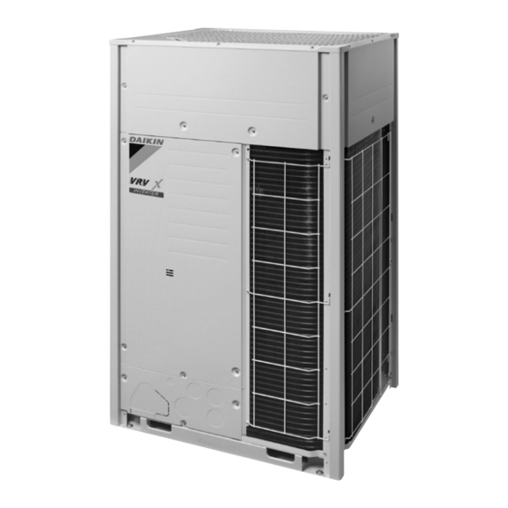
SiAF341904E External Appearance Outdoor Unit VRV X Series High-COP Type 12, 14, 16, 18, 20 HP 22, 24, 26, 28, 30, 32, 34 HP RXQ22AHRY1 RXQ12AHRY1 RXQ24AHRY1 RXQ14AHRY1 RXQ26AHRY1 RXQ16AHRY1 RXQ28AHRY1 RXQ18AHRY1 RXQ30AHRY1 RXQ20AHRY1 RXQ32AHRY1 RXQ34AHRY1 36, 38 HP 40 HP RXQ36AHRY1 RXQ40AHRY1 RXQ38AHRY1... - Page 18 External Appearance SiAF341904E VRV X Series Standard Type 6, 8, 10, 12 HP 14, 16, 18, 20 HP RXQ6ARY1 RXQ14ARY1 RXQ8ARY1 RXQ16ARY1 RXQ10ARY1 RXQ18ARY1 RXQ12ARY1 RXQ20ARY1 22, 24 HP 26, 28, 30 HP 32, 34, 36, 38, 40 HP RXQ22ANRY1 RXQ26ANRY1 RXQ32ANRY1 RXQ24ANRY1...
-
Page 19: Combination Of Outdoor Units
Capacity range 12 HP 14 HP 16 HP 18 HP 20 HP 22 HP 24 HP 26 HP Model name RXQ12AHR RXQ14AHR RXQ16AHR RXQ18AHR RXQ20AHR RXQ22AHR RXQ24AHR RXQ26AHR Outdoor unit 1 RXQ6AR RXQ6AR RXQ8AR RXQ8AR RXQ10AR RXQ6AR RXQ8AR RXQ8AR Outdoor unit 2... - Page 20 Combination of Outdoor Units SiAF341904E VRV X Series Standard Type Capacity range 6 HP 8 HP 10 HP 12 HP 14 HP 16 HP 18 HP 20 HP Model name RXQ6AR RXQ8AR RXQ10AR RXQ12AR RXQ14AR RXQ16AR RXQ18AR RXQ20AR Capacity range 22 HP 24 HP 26 HP...
-
Page 21: Capacity Range
SiAF341904E Capacity Range 4. Capacity Range Capacity Range for VRV Indoor Units Only 4.1.1 Connection Ratio Total capacity index of the indoor units Connection ratio = Capacity index of the outdoor units Max. connection ratio Min. Including Other Type connection FXMQ-PB FXFSQ25AR indoor unit... - Page 22 Maximum number of Capacity Model name Combination connectable indoor units connectable indoor units index 1 1 32.0 RXQ12AHR RXQ6AR × 2 150 to 390 (480) 19 (24) 38.4 RXQ14AHR RXQ6AR + RXQ8AR 175 to 455 (560) 22 (28) 44.8 RXQ16AHR RXQ8AR ×...
- Page 23 SiAF341904E Capacity Range VRV X Series Standard Type Total capacity index of Maximum number of Capacity Model name Combination connectable indoor units connectable indoor units index 1 1 16.0 RXQ6AR RXQ6AR 75 to 195 (300) 9 (15) 22.4 RXQ8AR RXQ8AR 100 to 260 (400) 13 (20) 28.0...
-
Page 24: Specifications
Specifications SiAF341904E 5. Specifications VRV X Series High-COP Type Model Name (Combination Unit) RXQ12AHRY1 RXQ14AHRY1 Model Name (Independent Unit) RXQ6ARY1+RXQ6ARY1 RXQ6ARY1+RXQ8ARY1 Power supply 3 phase, 380-415 V, 50/60 Hz 3 phase, 380-415 V, 50/60 Hz 1 Cooling capacity kcal/h 27,500 33,000 Btu/h 109,000... - Page 25 SiAF341904E Specifications Model Name (Combination Unit) RXQ16AHRY1 RXQ18AHRY1 Model Name (Independent Unit) RXQ8ARY1+RXQ8ARY1 RXQ8ARY1+RXQ10ARY1 Power supply 3 phase, 380-415 V, 50/60 Hz 3 phase, 380-415 V, 50/60 Hz 1 Cooling capacity kcal/h 38,500 43,300 Btu/h 153,000 172,000 44.8 50.4 Casing color Ivory white (5Y7.5/1) Ivory white (5Y7.5/1) Dimensions (H ×...
- Page 26 Specifications SiAF341904E Model Name (Combination Unit) RXQ20AHRY1 RXQ22AHRY1 Model Name (Independent Unit) RXQ10ARY1+RXQ10ARY1 RXQ6ARY1+RXQ8ARY1+RXQ8ARY1 Power supply 3 phase, 380-415 V, 50/60 Hz 3 phase, 380-415 V, 50/60 Hz 1 Cooling capacity kcal/h 48,200 52,300 Btu/h 191,000 207,000 60.8 Casing color Ivory white (5Y7.5/1) Ivory white (5Y7.5/1) Dimensions (H ×...
- Page 27 SiAF341904E Specifications Model Name (Combination Unit) RXQ24AHRY1 RXQ26AHRY1 Model Name (Independent Unit) RXQ8ARY1+RXQ8ARY1+RXQ8ARY1 RXQ8ARY1+RXQ8ARY1+RXQ10ARY1 Power supply 3 phase, 380-415 V, 50/60 Hz 3 phase, 380-415 V, 50/60 Hz 1 Cooling capacity kcal/h 57,800 62,600 Btu/h 229,000 248,000 67.2 72.8 Casing color Ivory white (5Y7.5/1) Ivory white (5Y7.5/1) Dimensions (H ×...
- Page 28 Specifications SiAF341904E Model Name (Combination Unit) RXQ28AHRY1 RXQ30AHRY1 Model Name (Independent Unit) RXQ8ARY1+RXQ8ARY1+RXQ12ARY1 RXQ8ARY1+RXQ10ARY1+RXQ12ARY1 Power supply 3 phase, 380-415 V, 50/60 Hz 3 phase, 380-415 V, 50/60 Hz 1 Cooling capacity kcal/h 67,300 72,200 Btu/h 267,000 286,000 78.3 83.9 Casing color Ivory white (5Y7.5/1) Ivory white (5Y7.5/1) Dimensions (H ×...
- Page 29 SiAF341904E Specifications Model Name (Combination Unit) RXQ32AHRY1 RXQ34AHRY1 Model Name (Independent Unit) RXQ8ARY1+RXQ12ARY1+RXQ12ARY1 RXQ10ARY1+RXQ12ARY1+RXQ12ARY1 Power supply 3 phase, 380-415 V, 50/60 Hz 3 phase, 380-415 V, 50/60 Hz 1 Cooling capacity kcal/h 76,900 81,700 Btu/h 305,000 324,000 89.4 Casing color Ivory white (5Y7.5/1) Ivory white (5Y7.5/1) Dimensions (H ×...
- Page 30 Specifications SiAF341904E Model Name (Combination Unit) RXQ36AHRY1 RXQ38AHRY1 Model Name (Independent Unit) RXQ10ARY1+RXQ12ARY1+RXQ14ARY1 RXQ12ARY1+RXQ12ARY1+RXQ14ARY1 Power supply 3 phase, 380-415 V, 50/60 Hz 3 phase, 380-415 V, 50/60 Hz 1 Cooling capacity kcal/h 87,300 92,000 Btu/h 346,000 365,000 101.5 Casing color Ivory white (5Y7.5/1) Ivory white (5Y7.5/1) Dimensions (H ×...
- Page 31 SiAF341904E Specifications Model Name (Combination Unit) RXQ40AHRY1 RXQ42AHRY1 Model Name (Independent Unit) RXQ12ARY1+RXQ14ARY1+RXQ14ARY1 RXQ14ARY1+RXQ14ARY1+RXQ14ARY1 Power supply 3 phase, 380-415 V, 50/60 Hz 3 phase, 380-415 V, 50/60 Hz 1 Cooling capacity kcal/h 97,600 103,000 Btu/h 387,000 409,000 113.5 Casing color Ivory white (5Y7.5/1) Ivory white (5Y7.5/1) Dimensions (H ×...
- Page 32 Specifications SiAF341904E Model Name (Combination Unit) RXQ44AHRY1 Model Name (Independent Unit) RXQ14ARY1+RXQ14ARY1+RXQ16ARY1 Power supply 3 phase, 380-415 V, 50/60 Hz 1 Cooling capacity kcal/h 108,000 Btu/h 427,000 Casing color Ivory white (5Y7.5/1) Dimensions (H × W × D) (1,657×1,240×765)+(1,657×1,240×765)+(1,657×1,240×765) Heat exchanger Cross fin coil Compressor Type...
- Page 33 SiAF341904E Specifications VRV X Series Standard Type Model Name RXQ6ARY1 RXQ8ARY1 Power supply 3 phase, 380-415 V, 50/60 Hz 3 phase, 380-415 V, 50/60 Hz 1 Cooling capacity kcal/h 13,800 19,300 Btu/h 54,600 76,400 16.0 22.4 Casing color Ivory white (5Y7.5/1) Ivory white (5Y7.5/1) Dimensions (H ×...
- Page 34 Specifications SiAF341904E Model Name RXQ10ARY1 RXQ12ARY1 Power supply 3 phase, 380-415 V, 50/60 Hz 3 phase, 380-415 V, 50/60 Hz 1 Cooling capacity kcal/h 24,100 28,800 Btu/h 95,500 114,000 28.0 33.5 Casing color Ivory white (5Y7.5/1) Ivory white (5Y7.5/1) Dimensions (H × W × D) 1,657×930×765 1,657×930×765 Heat exchanger...
- Page 35 SiAF341904E Specifications Model Name RXQ14ARY1 RXQ16ARY1 Power supply 3 phase, 380-415 V, 50/60 Hz 3 phase, 380-415 V, 50/60 Hz 1 Cooling capacity kcal/h 34,400 38,700 Btu/h 136,000 154,000 40.0 45.0 Casing color Ivory white (5Y7.5/1) Ivory white (5Y7.5/1) Dimensions (H × W × D) 1,657×1,240×765 1,657×1,240×765 Heat exchanger...
- Page 36 Specifications SiAF341904E Model Name RXQ18ARY1 RXQ20ARY1 Power supply 3 phase, 380-415 V, 50/60 Hz 3 phase, 380-415 V, 50/60 Hz 1 Cooling capacity kcal/h 43,000 48,200 Btu/h 171,000 191,000 50.0 56.0 Casing color Ivory white (5Y7.5/1) Ivory white (5Y7.5/1) Dimensions (H × W × D) 1,657×1,240×765 1,657×1,240×765 Heat exchanger...
- Page 37 SiAF341904E Specifications Model Name (Combination Unit) RXQ22ANRY1 RXQ24ANRY1 Model Name (Independent Unit) RXQ10ARY1+RXQ12ARY1 RXQ12ARY1+RXQ12ARY1 Power supply 3 phase, 380-415 V, 50/60 Hz 3 phase, 380-415 V, 50/60 Hz 1 Cooling capacity kcal/h 52,900 57,600 Btu/h 210,000 229,000 61.5 67.0 Casing color Ivory white (5Y7.5/1) Ivory white (5Y7.5/1) Dimensions (H ×...
- Page 38 Specifications SiAF341904E Model Name (Combination Unit) RXQ26ANRY1 RXQ28ANRY1 Model Name (Independent Unit) RXQ12ARY1+RXQ14ARY1 RXQ12ARY1+RXQ16ARY1 Power supply 3 phase, 380-415 V, 50/60 Hz 3 phase, 380-415 V, 50/60 Hz 1 Cooling capacity kcal/h 63,200 67,500 Btu/h 251,000 268,000 73.5 78.5 Casing color Ivory white (5Y7.5/1) Ivory white (5Y7.5/1) Dimensions (H ×...
- Page 39 SiAF341904E Specifications Model Name (Combination Unit) RXQ30ANRY1 RXQ32ANRY1 Model Name (Independent Unit) RXQ12ARY1+RXQ18ARY1 RXQ14ARY1+RXQ18ARY1 Power supply 3 phase, 380-415 V, 50/60 Hz 3 phase, 380-415 V, 50/60 Hz 1 Cooling capacity kcal/h 71,800 77,400 Btu/h 285,000 307,000 83.5 90.0 Casing color Ivory white (5Y7.5/1) Ivory white (5Y7.5/1) Dimensions (H ×...
- Page 40 Specifications SiAF341904E Model Name (Combination Unit) RXQ34ANRY1 RXQ36ANRY1 Model Name (Independent Unit) RXQ16ARY1+RXQ18ARY1 RXQ18ARY1+RXQ18ARY1 Power supply 3 phase, 380-415 V, 50/60 Hz 3 phase, 380-415 V, 50/60 Hz 1 Cooling capacity kcal/h 81,700 86,000 Btu/h 324,000 341,000 95.0 Casing color Ivory white (5Y7.5/1) Ivory white (5Y7.5/1) Dimensions (H ×...
- Page 41 SiAF341904E Specifications Model Name (Combination Unit) RXQ38ANRY1 RXQ40ANRY1 Model Name (Independent Unit) RXQ18ARY1+RXQ20ARY1 RXQ20ARY1+RXQ20ARY1 Power supply 3 phase, 380-415 V, 50/60 Hz 3 phase, 380-415 V, 50/60 Hz 1 Cooling capacity kcal/h 91,200 96,300 Btu/h 362,000 382,000 Casing color Ivory white (5Y7.5/1) Ivory white (5Y7.5/1) Dimensions (H ×...
- Page 42 Specifications SiAF341904E Model Name (Combination Unit) RXQ42ANRY1 RXQ44ANRY1 Model Name (Independent Unit) RXQ12ARY1+RXQ12ARY1+RXQ18ARY1 RXQ12ARY1+RXQ12ARY1+RXQ20ARY1 Power supply 3 phase, 380-415 V, 50/60 Hz 3 phase, 380-415 V, 50/60 Hz 1 Cooling capacity kcal/h 101,000 106,000 Btu/h 399,000 420,000 Casing color Ivory white (5Y7.5/1) Ivory white (5Y7.5/1) Dimensions (H ×...
- Page 43 SiAF341904E Specifications Model Name (Combination Unit) RXQ46ANRY1 RXQ48ANRY1 Model Name (Independent Unit) RXQ14ARY1+RXQ14ARY1+RXQ18ARY1 RXQ14ARY1+RXQ16ARY1+RXQ18ARY1 Power supply 3 phase, 380-415 V, 50/60 Hz 3 phase, 380-415 V, 50/60 Hz 1 Cooling capacity kcal/h 112,000 116,000 Btu/h 444,000 461,000 Casing color Ivory white (5Y7.5/1) Ivory white (5Y7.5/1) Dimensions (H ×...
- Page 44 Specifications SiAF341904E Model Name (Combination Unit) RXQ50ANRY1 RXQ52ANRY1 Model Name (Independent Unit) RXQ14ARY1+RXQ18ARY1+RXQ18ARY1 RXQ16ARY1+RXQ18ARY1+RXQ18ARY1 Power supply 3 phase, 380-415 V, 50/60 Hz 3 phase, 380-415 V, 50/60 Hz 1 Cooling capacity kcal/h 120,000 125,000 Btu/h 478,000 495,000 Casing color Ivory white (5Y7.5/1) Ivory white (5Y7.5/1) Dimensions (H ×...
- Page 45 SiAF341904E Specifications Model Name (Combination Unit) RXQ54ANRY1 RXQ56ANRY1 Model Name (Independent Unit) RXQ18ARY1+RXQ18ARY1+RXQ18ARY1 RXQ18ARY1+RXQ18ARY1+RXQ20ARY1 Power supply 3 phase, 380-415 V, 50/60 Hz 3 phase, 380-415 V, 50/60 Hz 1 Cooling capacity kcal/h 129,000 134,000 Btu/h 512,000 532,000 Casing color Ivory white (5Y7.5/1) Ivory white (5Y7.5/1) Dimensions (H ×...
- Page 46 Specifications SiAF341904E Model Name (Combination Unit) RXQ58ANRY1 RXQ60ANRY1 Model Name (Independent Unit) RXQ18ARY1+RXQ20ARY1+RXQ20ARY1 RXQ20ARY1+RXQ20ARY1+RXQ20ARY1 Power supply 3 phase, 380-415 V, 50/60 Hz 3 phase, 380-415 V, 50/60 Hz 1 Cooling capacity kcal/h 139,000 144,000 Btu/h 553,000 573,000 Casing color Ivory white (5Y7.5/1) Ivory white (5Y7.5/1) Dimensions (H ×...
- Page 47 SiAF341904E Part 2 Refrigerant Circuit 1. Refrigerant Circuit (Piping Diagrams) ...........42 1.1 Outdoor Unit ...................42 1.2 VRV Indoor Unit ..................46 2. Functional Parts Layout ................47 2.1 RXQ6/8/10/12A ..................47 2.2 RXQ14/16/18/20A ..................48 3. Refrigerant Flow for Each Operation Mode...........49 3.1 RXQ6/8/10/12/14A .................49 3.2 RXQ16/18/20A ..................51 Part 2 Refrigerant Circuit...
-
Page 48: Refrigerant Circuit Part
Refrigerant Circuit (Piping Diagrams) SiAF341904E 1. Refrigerant Circuit (Piping Diagrams) Outdoor Unit 1.1.1 RXQ6/8/10/12/14A No. in Electric piping Name Function symbol diagram Inverter compressor Inverter compressor is operated in multi-steps according to Te. Inverter fan The fan rotation speed is varied by using inverter. Inverter fan (RXQ14A only) Electronic expansion... - Page 49 SiAF341904E Refrigerant Circuit (Piping Diagrams) Part 2 Refrigerant Circuit...
- Page 50 Refrigerant Circuit (Piping Diagrams) SiAF341904E 1.1.2 RXQ16/18/20A No. in Electric piping Name Function symbol diagram Inverter compressor Inverter compressor is operated in multi-steps according to Te. Inverter fan The fan rotation speed is varied by using inverter. Electronic expansion PI control is applied to keep the outlet superheated degree of subcooling heat valve (Injection) exchanger constant.
- Page 51 SiAF341904E Refrigerant Circuit (Piping Diagrams) Part 2 Refrigerant Circuit...
-
Page 52: Vrv Indoor Unit
Refrigerant Circuit (Piping Diagrams) SiAF341904E VRV Indoor Unit No. in piping Electric Name Applicable model Function diagram symbol Electronic expansion valve All indoor units Used for gas superheated degree control while in cooling. Suction air thermistor All indoor units Used for thermostat control. Indoor liquid pipe thermistor All indoor units Used for gas superheated degree... -
Page 53: Functional Parts Layout
SiAF341904E Functional Parts Layout 2. Functional Parts Layout RXQ6/8/10/12A Top View Solenoid Valve (Oil return 1) (Y3S) Electronic expansion valve (Injection) (Y2E) Thermistor (Subcooling heat exchanger gas pipe) (R6T) Thermistor (Heat Thermistor exchanger liquid pipe) (Subcooling heat (R4T) exchanger liquid pipe) (R5T) Front View Inverter fan... -
Page 54: Rxq14/16/18/20A
Functional Parts Layout SiAF341904E RXQ14/16/18/20A Top View Solenoid valve (Oil return 2) (Y4S) Solenoid valve (Oil return 1) (Y3S) Low pressure sensor (S1NPL) Electronic expansion valve (Injection) (Y2E) Front View Inverter fan (M1F) Thermistor (Outdoor air) (R1T) Inverter fan (M2F) High pressure switch (For M2C compressor) (S2PH) -
Page 55: Refrigerant Flow For Each Operation Mode
SiAF341904E Refrigerant Flow for Each Operation Mode 3. Refrigerant Flow for Each Operation Mode RXQ6/8/10/12/14A Cooling Operation High temperature, high pressure, gas High temperature, high pressure, liquid Low temperature, low pressure Indoor unit operation Fan ON Fan ON Fan OFF Heat exchanger Heat exchanger Heat exchanger... - Page 56 Refrigerant Flow for Each Operation Mode SiAF341904E Cooling Oil Return Operation High temperature, high pressure, gas High temperature, high pressure, liquid Low temperature, low pressure Indoor unit operation Heat exchanger Heat exchanger Heat exchanger EV: Normal EV: Normal EV: 224 pulse control control Filter...
-
Page 57: Rxq16/18/20A
SiAF341904E Refrigerant Flow for Each Operation Mode RXQ16/18/20A Cooling Operation High temperature, high pressure, gas High temperature, high pressure, liquid Low temperature, low pressure Indoor unit operation Fan OFF Heat exchanger Heat exchanger Heat exchanger EV: Normal control Filter Filter Filter Filter Filter... - Page 58 Refrigerant Flow for Each Operation Mode SiAF341904E Cooling Oil Return Operation High temperature, high pressure, gas High temperature, high pressure, liquid Low temperature, low pressure Indoor unit operation Fan OFF Fan ON Fan ON Heat exchanger Heat exchanger Heat exchanger EV: Normal EV: Normal EV: 224 pulse...
- Page 59 SiAF341904E Part 3 Remote Controller 1. Applicable Models .................54 2. Names and Functions ................56 2.1 BRC1E62 ....................56 2.2 BRC1E63 ....................58 2.3 BRC4C, BRC7E Series ................60 2.4 BRC4M151W16 ..................61 3. Main/Sub Setting...................64 3.1 Wired Remote Controller (BRC1E62, BRC1E63) ........64 3.2 When Wireless Remote Controller is Used Together......65 4.
-
Page 60: Applicable Models
Applicable Models SiAF341904E 1. Applicable Models Wired remote Wireless remote controller Wireless remote controller (New type: 5-step airflow rate) Series controller (Old type) Navigation Remote controller Receiver FXFSQ-AR BRC1E63 ― BRC7M632F-6 (1) FXMQ-PB BRC4C66 BRC4M151W16 BRC4M61-6 BRC1E63 FXMQ-AR ― BRC1E62 FXAQ-P BRC7EA619 BRC7M618-6... - Page 61 SiAF341904E Applicable Models Function list FXFSQ-AR Category Function BRC1E63 BRC4M151 ON/OFF operation ● ● Setting temperature ● ● Swing pattern selection ● ● Switchable fan speed (Ventilation amount) ● ● Display switching function ● — Basic performance Backlight function ● ●...
-
Page 62: Names And Functions
Names and Functions SiAF341904E 2. Names and Functions BRC1E62 (6) Right button (1) Mode Selector button Used to highlight the next items on the Used to select the operation mode. right-hand side. (2) Airflow Setting button Display contents are changed to next Used to indicate the Airflow Rate (Air screen per page. - Page 63 SiAF341904E Names and Functions Main Menu • Airflow direction • Quick start • Ventilation • Energy saving options • Schedule • Filter auto clean • Maintenance information • Configuration • Current settings Main Menu screen • Clock & calendar • Language Press Press the Cancel the Menu/Enter...
-
Page 64: Brc1E63
Names and Functions SiAF341904E BRC1E63 (6) Right button (1) Mode Selector button Used to highlight the next items on the Used to select the operation mode. right-hand side. (2) Airflow Setting button Display contents are changed to next screen per page. Used to indicate the Airflow Rate (Air Volume / Fan Speed) / Airflow Direction (7) Left button... - Page 65 SiAF341904E Names and Functions Main Menu • Circulation airflow • Airflow direction • Individual air direction • Quick start • Ventilation • Energy saving options • Schedule • Filter auto clean • Maintenance information Main Menu screen • Configuration • Current settings •...
-
Page 66: Brc4C, Brc7E Series
Names and Functions SiAF341904E BRC4C, BRC7E Series ON OFF DOWN ON OFF TEMP TIME DOWN RESERVE CANCEL TIMER TEST MODE SWING TEST TEST DISPLAY (SIGNAL TRANSMISSION) FAN SPEED CONTROL BUTTON Press this button to select the fan speed, HIGH or This lights up when a signal is being transmitted. -
Page 67: Brc4M151W16
SiAF341904E Names and Functions BRC4M151W16 TEMPERATURE SETTING BUTTON DISPLAY (SIGNAL TRANSMISSION) Use this button for SETTING TEMPERATURE. This blinks when a signal is being transmitted. BACKLIGHT BUTTON DISPLAY (OPERATION MODE) Press this button to turn the backlight on or off. This display shows the current OPERATION SIGNAL TRANSMITTER MODE. - Page 68 Names and Functions SiAF341904E 2.4.1 Signal Receiver Unit BRC7M632F-6, BRC7M618-6 BRC4M61-6 Signal receiver unit installed type Signal receiver unit separate type (Example) 26 25 ∗ Layout of the display area varies by model. EMERGENCY OPERATION SWITCH This switch is readily used if the remote controller does not work.
- Page 69 SiAF341904E Names and Functions 2.4.2 How to Check Initial Set Value Press the INSPECTION button to check the initial set value. Press the INSPECTION button twice to return to the normal mode. Initial set value Indoor unit model type Initial set value Ceiling mounted cassette FXFSQ-AR 2111...
-
Page 70: Main/Sub Setting
Main/Sub Setting SiAF341904E 3. Main/Sub Setting Main/Sub setting is necessary when 1 indoor unit is controlled by 2 remote controllers. The remote controllers are set at factory to Main, so you have to change one remote controller from Main to Sub. To change a remote controller from Main to Sub, proceed as follows: Wired Remote Controller (BRC1E62, BRC1E63) 3.1.1 Field Settings The designation of the main and sub remote controllers can be swapped. -
Page 71: When Wireless Remote Controller Is Used Together
SiAF341904E Main/Sub Setting 2. When 2 remote controllers are being used, it is not possible to change the setting from Main to Sub if one of the remote controllers is already set as Main. When Wireless Remote Controller is Used Together When using both a wired and a wireless remote controller for 1 indoor unit, the wired controller should be set to Main. -
Page 72: Address Setting For Wireless Remote Controller
Address Setting for Wireless Remote Controller SiAF341904E 4. Address Setting for Wireless Remote Controller If setting multiple wireless remote controllers to operate in one room, perform address setting for the receiver and the wireless remote controller. (This includes an individual remote controller control using the group operation.) (For the wiring for the group operation, please refer to the installation manual attached to the indoor unit and technical guide.) Setting for Signal Receiver PCB... - Page 73 SiAF341904E Address Setting for Wireless Remote Controller Setting for wireless remote controller (BRC4C, BRC7E series) The address for the wireless remote controller is set to 1 at the factory. To change the setting, proceed as follows: 1. Press FILTER SIGN RESET button and INSPECTION/TEST button at the same time for 4 seconds to enter field setting mode.
- Page 74 Address Setting for Wireless Remote Controller SiAF341904E Setting for wireless remote controller (BRC4M151W16) The address for the wireless remote controller is set to 1 at the factory. To change the setting, proceed as follows: 1. Hold down the FILTER SIGN RESET button and the INSPECTION button for at least 4 seconds to get the Field Setting mode.
- Page 75 SiAF341904E Address Setting for Wireless Remote Controller Multiple Settings A/b The command such as operation mode or temperature setting by this remote controller will be rejected when the target indoor unit operation is restricted as by an external control such as centralized control.
-
Page 76: Centralized Control Group No. Setting
Centralized Control Group No. Setting SiAF341904E 5. Centralized Control Group No. Setting BRC1E62, BRC1E63 Group No. Setting (Group) Basic screen is displayed. Press and hold Press the Cancel the Cancel button button once. for 4 seconds or more. Select Group Address and then press the Menu/Enter button. - Page 77 SiAF341904E Centralized Control Group No. Setting Group No. Setting (Unit) Basic screen is displayed. Press and hold Press the Cancel the Cancel button button once. for 4 seconds or Select Group Address more. and then press the Menu/Enter button. Service Item 2 is settings menu displayed.
-
Page 78: Brc4C, Brc7E Series
Centralized Control Group No. Setting SiAF341904E BRC4C, BRC7E Series Group No. setting by wireless remote controller for centralized control 1. When in the normal mode, press INSPECTION/TEST button for 4 seconds or more to enter field setting mode. 2. Set mode No. 00 with MODE button. 3. -
Page 79: Service Settings Menu, Maintenance Menu
SiAF341904E Service Settings Menu, Maintenance Menu 6. Service Settings Menu, Maintenance Menu BRC1E62, BRC1E63 Operating the remote controller allows service data to be acquired and various services to be set. Basic screen is displayed. Press and hold the Press the Cancel Cancel button button once. - Page 80 Service Settings Menu, Maintenance Menu SiAF341904E 6.1.1 Service Settings Menu Service settings Item 2 Remarks menu Test — — Operation Maintenance None — Contact Maintenance Contact —, 0 to 9 (in order) Field Indoor Unit No. — Settings Mode No. —...
- Page 81 SiAF341904E Service Settings Menu, Maintenance Menu 6.1.2 Maintenance Menu Maintenance Item 2 Remarks Menu Model Name Unit No. Select the unit number you want to check. Indoor unit The model names are displayed. (A model code may be displayed instead, depending on Outdoor unit the particular model.) R-32 mark display...
- Page 82 Service Settings Menu, Maintenance Menu SiAF341904E Maintenance Item 2 Remarks Menu Addressed Unit No.: 0 - 15 Select the unit number you want to check. Sensor Code Value Remote controller thermistor (°C) Suction air thermistor (°C) 5 Heat exchanger liquid pipe thermistor (°C) Heat exchanger gas pipe thermistor (°C) Indoor unit address No.
-
Page 83: Brc4C, Brc7E Series
SiAF341904E Service Settings Menu, Maintenance Menu BRC4C, BRC7E Series Mode number UP button DOWN button RESERVE button MODE button INSPECTION/TEST button 1. Press INSPECTION/TEST button for 4 seconds during normal mode to enter field setting mode. 2. Press INSPECTION/TEST button for 4 seconds to enter service mode. 3. - Page 84 SiAF341904E Part 4 Functions and Control 1. Operation Flowchart................79 2. Stop Control ..................80 2.1 Abnormal Shutdown ................80 2.2 Slave Unit Stops during Master Unit Operation........80 3. Standby Control ..................81 3.1 Restart Standby..................81 4. Startup Control ..................82 4.1 Cooling Startup Control ................82 5.
-
Page 85: Operation Flowchart
SiAF341904E Operation Flowchart 1. Operation Flowchart For detailed description of each function in the flow, refer to the details on related function on the following pages. Stop control (1) Abnormal shutdown (2) Slave unit stops during master unit operation Special control Standby control (1) Restart standby Thermostat ON... -
Page 86: Stop Control
Stop Control SiAF341904E 2. Stop Control Abnormal Shutdown If abnormal situation occurs to protect the compressor, initial thermostat OFF stops the outdoor unit. Outdoor control will perform a retry start. When the retry attempts reach a certain number, system will stop and error code is displayed on the remote control. -
Page 87: Standby Control
SiAF341904E Standby Control 3. Standby Control Restart Standby Used to forcedly stop the compressor for a period of 5 minutes, in order to prevent the frequent ON/OFF of the compressor and equalize the pressure within the refrigerant system. In addition, the outdoor fan carry out the residual operation for a while to accelerate pressure equalizing and to suppress melting of the refrigerant to the evaporator. -
Page 88: Startup Control
Startup Control SiAF341904E 4. Startup Control Before starting the compressor: The capacitor is charged in the DC circuit of the inverter circuit, and “Pre-pressure equalization” is performed to reducing the starting current of the compressor. Pc: High pressure sensor detection value Pe: Low pressure sensor detection value Ta: Outdoor air temperature Te: Low pressure equivalent saturation temperature... -
Page 89: Normal Operation
SiAF341904E Normal Operation 5. Normal Operation List of Functions in Normal Operation Pc : High pressure sensor detection value Pe : Low pressure sensor detection value Electric Part Name RXQ6-12A RXQ14A RXQ16-20A Function of Functional Part Symbol Inverter compressor 1 PI control by Te target. -
Page 90: Compressor Capacity Control
Normal Operation SiAF341904E Compressor Capacity Control Te: Low pressure equivalent saturation temperature Capacity steps The compressor rotation speed is changed according to the control pressure. Cooling: suction pressure sensor value is converted into evaporation saturated temperature (relation between pressure and evaporating temperature based on characteristics of refrigerant R-410A). -
Page 91: Operating Priority And Rotation Of Compressors
SiAF341904E Normal Operation Operating Priority and Rotation of Compressors Each compressor operates in the following order of priority. In the case of multi-outdoor-unit system, each compressor operates in any of Pattern 1 through Pattern 3 according to the rotation of outdoor units. M1C: Inverter compressor 1 M2C: Inverter compressor 2 Pattern 1... -
Page 92: Compressor Step Control
Normal Operation SiAF341904E Compressor Step Control The actual rotation speed per second of the compressor (rps) depends on the type of compressor: Actual rotation Model name Compressor speed RXQ6/8A RXQ10-14A RXQ16/18A RXQ20A (rps) JT1GUVDYR frequency/2 – M1C, M2C JT16KCVDYR frequency/3 –... -
Page 93: Protection Control
SiAF341904E Protection Control 6. Protection Control High Pressure Protection Control This high pressure protection control is used to prevent the activation of protection devices due to abnormal increase of high pressure and to protect compressors against the transient increase of high pressure. Cooling The following control is performed in the entire system. -
Page 94: Discharge Pipe Protection Control
Protection Control SiAF341904E Discharge Pipe Protection Control This discharge pipe protection control is used to protect the compressor internal temperature against an error or transient increase of discharge pipe temperature. The following control is performed for each compressor of single unit as well as multi units. Inverter compressor Normal operation Discharge pipe... -
Page 95: Inverter Protection Control
SiAF341904E Protection Control Inverter Protection Control Inverter current protection control and radiation fin temperature control are performed to prevent tripping due to an error, or transient inverter overcurrent, and fin temperature increase. In the case of multi-outdoor-unit system, each inverter compressor performs these controls in the following sequence. -
Page 96: Special Control
Special Control SiAF341904E 7. Special Control Outdoor Unit Rotation In the case of multi-outdoor-unit system, this outdoor unit rotation is used to prevent the compressor from breaking down due to unbalanced oil level between outdoor units. Details of outdoor unit rotation In the case of multi-outdoor-unit system, each outdoor unit is given an operating priority for the control. -
Page 97: Oil Return Operation
SiAF341904E Special Control Oil Return Operation In order to prevent the compressor from running out of oil, the oil return operation is conducted to recover oil that has flowed out from the compressor to the system side. Tc : High pressure equivalent saturation temperature Te : Low pressure equivalent saturation temperature Ts: Suction pipe temperature detected by thermistor R3T Starting conditions... -
Page 98: Inverter Pre-Heat Operation
Special Control SiAF341904E Inverter Pre-Heat Operation Inverter pre-heat function is performed by each compressor on its own. HTdi : Value of inverter compressor discharge pipe temperature (Tdi) compensated with outdoor air temperature Ta : Outdoor air temperature Teg : Low pressure equivalent saturation temperature (°C) Tfin : Fin thermistor temperature 1) System is stopped (all compressors are stopped) Power supply ON... -
Page 99: Outline Of Control (Indoor Unit)
SiAF341904E Outline of Control (Indoor Unit) 8. Outline of Control (Indoor Unit) Set Temperature and Control Target Temperature The relationship between remote controller set temperature and control target temperature is described below. Temperature ˚C Remote controller set temperature Cooling Control target temperature Examples are given to illustrate a control target temperature that satisfies the remote controller set temperature. - Page 100 Outline of Control (Indoor Unit) SiAF341904E 8.2.2 With Optional Infrared Presence/Floor Sensor The thermostat ON/OFF condition is determined by the difference between the remote controller set temperature and the detected temperature around people. Normal operation Cooling operation ΔT ≤ –1.0°C Normal operation Thermostat OFF (Thermostat ON)
-
Page 101: Automatic Airflow Rate Control
SiAF341904E Outline of Control (Indoor Unit) Automatic Airflow Rate Control The automatic airflow rate control (Five steps from H to L) is based on the difference between control target temperature and set temperature. When airflow Conditions Automatic airflow rate rate is set Cooling Thermostat ON The fan tap is determined... -
Page 102: Airflow Direction Control
Outline of Control (Indoor Unit) SiAF341904E Airflow Direction Control 8.4.1 Without Optional Infrared Presence/Floor Sensor Refer to the table below for controlling the horizontal flap (or the vertical flap) for airflow direction adjustment. Conditions FXAQ Cooling Direction set Thermostat ON Thermostat OFF Swing set Thermostat ON... -
Page 103: Auto Draft Reducing Control (Fxfsq Only)
SiAF341904E Outline of Control (Indoor Unit) Auto Draft Reducing Control (FXFSQ only) In the case where both this control is activated and auto airflow direction control (eco full automatic control) is set, when human presence is detected, the airflow direction is automatically set to horizontal (P0) to reduce discomfort by direct airflow. -
Page 104: Drain Pump Control
Outline of Control (Indoor Unit) SiAF341904E Drain Pump Control 8.7.1 Normal Operation Float switch Thermostat (running) Error display Drain pump 5 min. The float switch is ON in normal operation. When cooling operation starts (thermostat ON), the drain pump turns ON simultaneously. ... - Page 105 SiAF341904E Outline of Control (Indoor Unit) 8.7.3 If the Float Switch is OFF with the Thermostat OFF in Cooling Operation Float switch Thermostat (running) Error display Drain pump 5 min. 5 sec. When the float switch turns OFF, the drain pump turns ON simultaneously. ...
-
Page 106: Freeze-Up Prevention Control
Outline of Control (Indoor Unit) SiAF341904E Freeze-Up Prevention Control Freeze-Up Prevention by Off Cycle (Indoor Unit Individual Control) When the temperature detected by liquid pipe temperature thermistor of the indoor heat exchanger drops too low, the unit enters freeze-up prevention control in accordance with the following conditions, and is also set in accordance with the conditions given below. -
Page 107: Dew Condensation Prevention Control
SiAF341904E Outline of Control (Indoor Unit) Dew Condensation Prevention Control 8.9.1 FXFSQ Models Indoor operation under a certain condition will limit the swing range of the flaps. Position P0 continues for 30 minutes. Dew condensation Dew condensation prevention control OFF prevention control in action Thermostat OFF Refer to the table below for flap action under this control. -
Page 108: Electronic Expansion Valve Control
Outline of Control (Indoor Unit) SiAF341904E 8.10 Electronic Expansion Valve Control Electronic expansion valves in indoor units have the functions of conducting superheated degree control in cooling operation. However, if the indoor units receive any control command such as a protection control command or a special control command from the outdoor unit, the units will give a priority to the control command. -
Page 109: Circulation Airflow (Fxfsq Only)
SiAF341904E Outline of Control (Indoor Unit) 8.11 Circulation Airflow (FXFSQ only) Unevenness of room temperature and the startup time are improved by repeating 2-direction horizontal blow-off and swing alternately. 8.11.1 Initiation Conditions of Circulation Operation When operation starts (in the startup state) Circulation airflow operation is performed. - Page 110 Outline of Control (Indoor Unit) SiAF341904E 8.11.3 Operational Concept (Designer Panel) Cooling : Factory setting Movement pattern 01: Pattern 1 120 600 120 600 Appearance 02: Pattern 2 Time (sec.) 03: Pattern 3 13 (23)-14 04: Pattern 4 Indicates the horizontal flap is in the position of reducing airflow volume (the flap is inverted). Part 4 Functions and Control...
- Page 111 SiAF341904E Part 5 Field Settings and Test Operation 1. Field Settings for Indoor Unit...............106 1.1 Field Settings from Remote Controller ..........106 1.2 List of Field Settings for Indoor Unit .............111 1.3 Applicable Range of Field Settings ............113 1.4 Details of Field Settings for Indoor Unit..........114 1.5 Operation Control Mode ...............126 2.
-
Page 112: Field Settings For Indoor Unit
Field Settings for Indoor Unit SiAF341904E 1. Field Settings for Indoor Unit Field Settings from Remote Controller Individual function of indoor unit can be changed from the remote controller. At the time of installation or after service inspection / repair, make the field setting in accordance with the following description. - Page 113 SiAF341904E Field Settings for Indoor Unit Press Menu/Enter button. Setting Setting confirmation screen confirmation screen is displayed. Select Yes and press Menu/Enter button. Setting details are determined and field settings screen returns. In the case of multiple setting changes, repeat (3) to (7). After all setting changes are completed, press Cancel button twice.
- Page 114 Field Settings for Indoor Unit SiAF341904E 1.1.2 BRC4C, BRC7E Series UP button Mode No. Field setting mode DOWN button RESERVE button First code No. MODE button Second code No. INSPECTION/TEST button Setting To set the field settings, you have to change: ...
- Page 115 SiAF341904E Field Settings for Indoor Unit 1.1.3 BRC4M151W16 Mode No. First code Second code No. Setting To set the field settings, you have to change: Mode No. First code No. Second code No. To change the field settings, proceed as follows: 1.
- Page 116 Field Settings for Indoor Unit SiAF341904E 1.1.4 Simplified Remote Controller Mode No. First code Unit No. Second code No. (2)(8) (7) (4) (5) (6) 1. Remove the upper part of remote controller. 2. When in the normal mode, press the BS6 button (2) (field setting) to enter the field setting mode.
-
Page 117: List Of Field Settings For Indoor Unit
SiAF341904E Field Settings for Indoor Unit List of Field Settings for Indoor Unit : Factory setting Mode First Description Second Code No. Code (2) Filter cleaning Long life filter Approx. Approx. sign interval 10,000 5,000 hrs. hrs. Ultra long life Approx. - Page 118 Field Settings for Indoor Unit SiAF341904E Mode First Description Second Code No. Code (2) Direct duct connection (when the indoor unit and Heat Reclaim 2 (5) Not equipped Equipped — — Ventilator are connected by duct directly.) 15 (25) Drain pump and humidifier Not interlocked...
-
Page 119: Applicable Range Of Field Settings
SiAF341904E Field Settings for Indoor Unit Applicable Range of Field Settings First Code Mode No. Setting Contents FXFSQ-AR FXMQ-PB FXMQ-AR FXAQ-P Filter cleaning sign interval Filter type Remote controller thermistor ... -
Page 120: Details Of Field Settings For Indoor Unit
Field Settings for Indoor Unit SiAF341904E Details of Field Settings for Indoor Unit 1.4.1 Filter Cleaning Sign Interval, Filter Type When the setting 10 (20)-3 is set to 01 (Displayed), filter cleaning sign is displayed on the remote controller after a certain period of operation time. This setting is used to change the display interval of filter cleaning sign when the filter contamination is heavy. - Page 121 SiAF341904E Field Settings for Indoor Unit When the unit is equipped with an infrared presence/floor sensor: : Factory setting Mode No. Second Code No. First Code No. 10 (20) 11 (21) The thermistor to be used Remote controller thermistor — —...
- Page 122 Field Settings for Indoor Unit SiAF341904E 1.4.4 Time for Absence Area Detection (For units with the infrared presence sensor only) By selecting the energy-saving operation mode in the absence, the target temperature is shifted to the energy-saving end by 1°C (maximum 2°C) after the state of absence continues for a certain period of time.
- Page 123 SiAF341904E Field Settings for Indoor Unit 1.4.7 Setting the Rate of Human Detection (For units with the infrared presence/floor sensor only) Set the sensitivity of the infrared presence/floor sensor. The infrared presence/floor sensor can be disabled by selecting the Second code No. 04. When the infrared presence/floor sensor is disabled, the remote controller menu does not display some functions such as the automatic draft reduction, energy-saving operation in absence and halt in absence.
- Page 124 Field Settings for Indoor Unit SiAF341904E 1.4.9 Compensating the Temperature around People (For units with the infrared floor sensor) Change the ratio between the suction air temperature and floor temperature used to calculate the temperature around people. The temperature around people is calculated using the values of the suction air thermistor and the infrared floor sensor.
- Page 125 SiAF341904E Field Settings for Indoor Unit 1.4.12 Thermostat Differential Changeover Differential value during thermostat ON/OFF control can be changed. : Factory setting Mode First Second Contents Code No. Code No. 01 1ºC 12 (22) 0.5ºC 1.4.13 Auto Restart after Power Failure Reset : Factory setting Mode First...
- Page 126 Field Settings for Indoor Unit SiAF341904E 1.4.15 Compensating the Floor Temperature (Cooling) (For units with the infrared presence/floor sensor) Offset the detected value of the infrared presence/floor sensor with a certain temperature. This setting should be used to have the actual floor temperature detected when, for example, the unit is installed close to a wall.
- Page 127 SiAF341904E Field Settings for Indoor Unit FXFSQ with Designer panel : Factory setting Mode First Second FXFSQ25-80 FXFSQ100-140 Contents Code No. Code No. (All round outlet) (All round outlet) Lower than Lower than 01 Standard 2.4 m 3.2 m Lower than Lower than 13 (23)
- Page 128 Field Settings for Indoor Unit SiAF341904E 1.4.19 Airflow Direction Adjustment Range Make the following airflow direction setting according to the respective purpose. FXFSQ-AR, FXAQ-P : Factory setting Mode First Second Contents Code No. Code No. Draft prevention (upward) 13 (23) 02...
- Page 129 SiAF341904E Field Settings for Indoor Unit 1.4.21 Setting of Swing Patterns when Cooling Thermostat is OFF In cooling operation, when the airflow direction is set to swing, flaps swing even when the thermostat is OFF. This setting allows to change the airflow direction when the thermostat is OFF.
- Page 130 Field Settings for Indoor Unit SiAF341904E 1.4.25 Direct Duct Connection This is used when "fresh air intake kit equipped with fan" is connected. The indoor fan carries out residual operation for 1 minute after the thermostat is stopped. (For the purpose of preventing dust on the air filter from falling off.) : Factory setting Mode...
- Page 131 SiAF341904E Field Settings for Indoor Unit 1.4.30 Setting Restricted/Permitted for Airflow Block For Sensing flow type only Due to possibility of dew condensation, the airflow block function cannot be enabled when closure material kit, fresh air intake kit, natural / separately installed evaporation humidifier, or branch air duct.
-
Page 132: Operation Control Mode
Field Settings for Indoor Unit SiAF341904E Operation Control Mode The operation control mode is compatible with a variety of controls and operations by limiting the functions of the operation remote controller. Furthermore, operations such as remote controller ON/OFF can be limited in accordance with the combination conditions. (Refer to information on the next page.) Central remote controller is normally available for operations. - Page 133 SiAF341904E Field Settings for Indoor Unit How to Select Operation Mode Whether operation by remote controller will be possible or not for turning ON/OFF, controlling temperature or setting operation mode is selected and decided by the operation mode given on the right edge of the table below.
-
Page 134: Field Settings For Outdoor Unit
Field Settings for Outdoor Unit SiAF341904E 2. Field Settings for Outdoor Unit This section shows a list of field setting items possible to set at time of initial startup. For details of DIP switch setting, setting mode ("mode 2") and monitoring mode ("mode 1"), refer to information on the following pages. -
Page 135: Settings By Dip Switches
SiAF341904E Field Settings for Outdoor Unit Settings by DIP Switches For factory mounted board only. DIP switch Setting item Description Setting Do not change the factory settings. DS1-1 Not used ~DS1-4 OFF (Factory setting) Part 5 Field Settings and Test Operation... - Page 136 Field Settings for Outdoor Unit SiAF341904E 2.2.1 DIP Switch Setting Mounting a Spare PCB Caution: After replacement with spare PCB, be sure to make settings shown in the table below. The procedure for making settings of spare PCB is different from that used for factory settings described above.
- Page 137 SiAF341904E Field Settings for Outdoor Unit The figure below shows the required position of the DIP switches on spare PCB for RXQ-A. Change DIP switches at time of power disconnected. Application The setting method (represents the position of switches) model RXQ6/8A Set DS1-2, DS1-3, DS1-4 and DS2-2 to ON.
-
Page 138: Settings By Bs Buttons
Field Settings for Outdoor Unit SiAF341904E Settings by BS Buttons The following settings can be made using the BS buttons on the PCB. In case of a multi outdoor system, make these settings with the master outdoor unit (settings made with a slave unit are disabled). BS buttons 7 segment display (SEG1-3) SEG1 SEG2 SEG3... - Page 139 SiAF341904E Field Settings for Outdoor Unit Selection between normal mode, monitor mode (Mode 1) and setting mode (Mode 2). SEG1 SEG2 SEG3 Normal mode MODE (BS1) button for more than 5 sec. Press MODE (BS1) button once. Press (Initial condition) Monitor mode (Mode 1) Setting mode (Mode 2) Setting item selection...
-
Page 140: Normal Mode
Field Settings for Outdoor Unit SiAF341904E Normal Mode 1. Indoor/outdoor transmission status: Used to check for the initial status of indoor/outdoor transmission. SEG1 SEG2 SEG3 Blinking Initializing Initializing completed 2. Descriptions: Used to display an error content. SEG1 SEG2 SEG3 Normal Example: E7-01 Error... -
Page 141: Monitor Mode (Mode 1)
SiAF341904E Field Settings for Outdoor Unit Monitor Mode (Mode 1) In the monitor mode, information can be retrieved about settings related to performance, addresses, number of units and actual operation data. 2.5.1 Retrieve data by using BS button outdoor unit main PCB SEG1 SEG2 SEG3 Normal To enter monitor mode, press the... - Page 142 Field Settings for Outdoor Unit SiAF341904E 2.5.2 Overview of Monitor Mode (Mode 1) Item Contents Display Display 1 Description Description Master/slave outdoor unit Undefined Master unit Slave 1 unit Slave 2 unit Low noise operation state In normal operation display In low noise operation Demand operation state In normal operation In...
- Page 143 SiAF341904E Field Settings for Outdoor Unit Item Contents Display Display 1 Description Description Description of retry Refer to information in Check for (latest) Descriptions of Errors/Retries on page 138. Description of retry (1 cycle before) Description of retry (2 cycles before) Number of outdoor units Possible 0-63 connected in a multi...
- Page 144 Field Settings for Outdoor Unit SiAF341904E 2.5.3 Check for Descriptions of Errors/Retries Follow the procedure described below. This procedure is different than indicated in previous “Monitor mode”. The error codes for forced stop outdoor or retry are item: 17, 18, 19: description of error (outdoor system stopped operation). ...
-
Page 145: Setting Mode (Mode 2)
SiAF341904E Field Settings for Outdoor Unit Setting Mode (Mode 2) SEG1 SEG2 SEG3 Press and hold the MODE (BS1) button for 5 seconds or more and set to “Setting mode”. Normal MODE Selection of setting items Press the SET (BS2) button and set the 7 segment display to a setting item shown in the table below. -
Page 146: Item
Field Settings for Outdoor Unit SiAF341904E 2.6.1 Overview of Setting Mode (Mode 2) This overview shows the available settings by using the press buttons on the outdoor unit PCB. Item Contents Display Display Description Description Do not change contents. — —... - Page 147 SiAF341904E Field Settings for Outdoor Unit Item Contents Display Display Description Description External night- Low noise level when the external low Level 1 time low noise noise signal is input at option Level 2 operation level DTA104A61. Level 3 Level 4 Automatic night- Time to start automatic “night-time low About 8:00 PM...
-
Page 148: Seg Seg Description Seg Seg Seg 2 3 1 2
Field Settings for Outdoor Unit SiAF341904E Item Contents Display Display Description Description Do not change contents. — — — — Do not change contents. — — — — Do not change contents. — — — — Do not change contents. —... - Page 149 SiAF341904E Field Settings for Outdoor Unit 2.6.2 Details of Setting Mode (m2) m2-2: Low noise/demand address: address for low noise/demand operation. 1 or more systems (maximum 10 systems wired by “F1F2 OUT/D”) can operate use the LNO (Low Noise Operation) or/and the DE (Demand Control) by instruction of field supplied input to optional board DTA104A61/62.
- Page 150 Field Settings for Outdoor Unit SiAF341904E m2-21: Refrigerant recovery / vacuuming. Default value: 0. Recovery mode not active. Set 1: outdoor and indoor electronic expansion valves are opened fully (except EV3 for PCM vessel). Compressor(s) do not operate. ...
- Page 151 SiAF341904E Field Settings for Outdoor Unit m2-26: Start time automatic night-time low noise operation. When the auto night-time low noise operation is active (refer to field setting 2-22) outdoor will start when start time is reached time is reached. The time judgement is taken from outdoor air tendency. *When the outdoor air temperature becomes highest, the unit is sensed as 2:00 PM Night mode...
- Page 152 Field Settings for Outdoor Unit SiAF341904E In case there is more than 1 compressor in a system (outdoor is 14 HP or larger, or multi outdoor configuration) all compressor inverter PCBs will perform the power transistor check. In such case, disconnect U/V/W fasten terminals on all compressors.
- Page 153 SiAF341904E Field Settings for Outdoor Unit When operation parameters return to normal range, the capacity priority is switched OFF, enable to reduce airflow rate depending on night-time low noise operation is still required (end time for low night noise operation is not reached or external input night-time low noise operation is still closed).
- Page 154 Field Settings for Outdoor Unit SiAF341904E m2-39: Emergency operation “Slave 1”. To disable permanent compressor operation of “Slave 1” unit of a multi outdoor system: Default value: 0. Compressor operation enabled. Field set: Set 1: Inverter 1 compressor is disabled. ...
- Page 155 SiAF341904E Field Settings for Outdoor Unit 2: Quick. Undershoot during cooling operation is allowed compared to the requested refrigerant temperature, in order to achieve the required room temperature very fast. The overshoot is allowed from the start up moment. In case of cooling operation the evaporating temperature is allowed to go down to 6°C on temporary base depending on the situation.
-
Page 156: Eco Mode Setting
Field Settings for Outdoor Unit SiAF341904E Eco Mode Setting By connecting an external contact input in the input of mode configuration and external control adaptor (sold separately), you may control Eco mode setting, limiting compressor operation load and power consumption. When Eco mode is set as unavailable (Outdoor unit external control adaptor is unnecessary) Eco mode control is unavailable during cooling operation. -
Page 157: Setting Of Night-Time Low Noise Operation And Demand Operation
SiAF341904E Field Settings for Outdoor Unit Setting of Night-Time Low Noise Operation and Demand Operation Setting of Night-time Low Noise Operation By connecting the external contact input to the low noise input of the outdoor unit external control adaptor (optional), you can lower operating noise by 2-3 dB. Setting Content Level 1... -
Page 158: Level 1 (60%)
Field Settings for Outdoor Unit SiAF341904E Image of operation in the case of A Operation If capacity priority is set in sound Capacity priority setting, the fan speed will be increased according to the load of air conditioning when load is heavier. Rated Operation sound during low noise... - Page 159 SiAF341904E Field Settings for Outdoor Unit Setting of Demand Operation By connecting the external contact input to the demand input of the external control adaptor for outdoor unit (optional), the power consumption of unit operation can be saved suppressing the compressor operating condition.
- Page 160 Field Settings for Outdoor Unit SiAF341904E Image of operation in the case of A Power consumption Rated The power Demand level 1 Demand level 2 Demand level 3 consumption instructing instructing instructing during the demand level 1 instructing can be set with the Power consumption set by "Demand 1 level...
-
Page 161: Test Operation
SiAF341904E Test Operation 3. Test Operation Checks before Test Operation Before carrying out a test operation, proceed as follows: Step Action Make sure the voltage at the primary side of the safety breaker is: 415 V ± 10% for 3-phase units Fully open the liquid and the gas stop valve. -
Page 162: Test Operation Procedure
Test Operation SiAF341904E Test Operation Procedure The procedure below describes the test operation of the complete system. This operation checks and judges following items: Check of wrong wiring (communication check with indoor units). Check of the stop valves opening. ... -
Page 163: Turn Power On
SiAF341904E Test Operation Turn Power ON • Be sure to turn the power ON 6 hours before starting operation to protect Turn outdoor unit and indoor compressors. unit power ON. • Check to be sure the transmission is normal. Check the 7 segment display of In a normal condition, the 7-segment display is OFF. - Page 164 SiAF341904E Part 6 Service Diagnosis 1. Servicing Items to be Confirmed ............160 1.1 Troubleshooting..................160 1.2 Precautions for Maintenance..............160 2. Symptom-based Troubleshooting ............162 2.1 With Optional Infrared Presence/Floor Sensor........164 2.2 For All Outdoor Units................165 3. Refrigerant Properties (R-410A) ............166 4. Troubleshooting with Remote Controller..........167 4.1 Wired Remote Controller..............167 4.2 BRC4C, BRC7E Series ................168 4.3 BRC4M151W16 ...................170...
- Page 165 SiAF341904E 5.27 Electronic Expansion Valve Coil Abnormality........228 5.28 Discharge Pipe Temperature Abnormality ...........229 5.29 Wet Alarm.....................231 5.30 Refrigerant Overcharged..............233 5.31 Harness Abnormality (between Outdoor Unit Main PCB and Inverter PCB)..................234 5.32 Outdoor Fan PCB Abnormality.............235 5.33 Thermistor Abnormality ................236 5.34 High Pressure Sensor Abnormality ............238 5.35 Low Pressure Sensor Abnormality ............239 5.36 Inverter PCB Abnormality..............240 5.37 Momentary Power Failure during Test Operation ........242...
-
Page 166: Servicing Items To Be Confirmed
Servicing Items to be Confirmed SiAF341904E 1. Servicing Items to be Confirmed Troubleshooting (1) Initial verification and troubleshooting 1. Properly understand the end user's needs and issues. 2. Check the cause of errors according to the description provided by the end user. 3. - Page 167 SiAF341904E Servicing Items to be Confirmed (4) Precautions for outdoor unit multi system All the settings should be made in the master unit. Settings in the slave units are deemed unavailable. Differentiation of Master/Slave Units 1. The outdoor unit master unit is the unit which has the connecting wires to the indoor unit. All the other units are slave units.
-
Page 168: On (Max. 90 M)
Symptom-based Troubleshooting SiAF341904E 2. Symptom-based Troubleshooting Symptom Supposed Cause Countermeasure The system does not start operation at all. Blowout of fuse(s) Turn Off the power supply and then replace the fuse(s). Cutout of breaker(s) • If the knob of any breaker is in its OFF position, turn ON the power supply. - Page 169 SiAF341904E Symptom-based Troubleshooting Symptom Supposed Cause Countermeasure The airflow The airflow direction is not Automatic control Normal operation. direction is not corresponding to that reproduced displayed on the remote according to the controller. setting. The flap does not swing. A white mist Indoor unit Uneven temperature distribution Clean the inside of the indoor unit.
-
Page 170: Automatic
Symptom-based Troubleshooting SiAF341904E With Optional Infrared Presence/Floor Sensor Problem Measure 1 Louver operation different from setting Refer to the flowchart below. Individual airflow direction setting different from the actual · Check the "Louver operation different from setting" error airflow direction diagnosis. -
Page 171: For All Outdoor Units
SiAF341904E Symptom-based Troubleshooting For All Outdoor Units Problem Measure Decrease of main circuit power supply insulation Define the measure using the flowchart below. resistance (Less than 1 M) Decrease of main circuit power supply insulation resistance Cut the power supply. Remove the compressor wiring from the power supply terminal. -
Page 172: Refrigerant Properties (R-410A)
Refrigerant Properties (R-410A) SiAF341904E 3. Refrigerant Properties (R-410A) 3.90 4.00 3.80 3.70 3.50 3.60 3.40 3.30 3.10 3.20 3.00 2.90 2.70 2.80 2.60 2.50 2.30 2.40 2.20 2.10 1.90 2.00 1.80 1.70 1.60 1.50 1.40 1.30 1.20 1.10 1.00 0.90 0.80 0.70 0.60... -
Page 173: Troubleshooting With Remote Controller
SiAF341904E Troubleshooting with Remote Controller 4. Troubleshooting with Remote Controller Wired Remote Controller 4.1.1 BRC1E62, BRC1E63 The illustrations are for BRC1E63 as representative. The following message is displayed on the screen when an error (or a warning) occurs during operation. Check the error code and take the corrective action specified for the particular model. -
Page 174: Brc4C, Brc7E Series
Troubleshooting with Remote Controller SiAF341904E BRC4C, BRC7E Series If the unit stops due to an error, the operation indicating LED on the signal receiving part of indoor unit blinks. The error code can be determined by following the procedure described below. (The error code is displayed when an operation error has occurred. - Page 175 SiAF341904E Troubleshooting with Remote Controller 7. Press MODE button to return to the normal mode. If you do not press any button for 1 minute, the remote controller automatically returns to the normal mode. 2. Change the unit number with Normal mode UP button or DOWN button.
-
Page 176: Brc4M151W16
Troubleshooting with Remote Controller SiAF341904E BRC4M151W16 When the air conditioner stops in emergency, the operating indicator lamp on the indoor unit starts blinking. Take the following steps yourself to read the error code that appears on the display. Contact your local dealer with this code. It will help pinpoint the cause of the trouble, speeding up the repair. -
Page 177: Error Codes And Descriptions
SiAF341904E Troubleshooting with Remote Controller Error Codes and Descriptions k: ON h: OFF l: Blink Operation Reference Error code Error contents lamp page Indoor Unit External protection device abnormality Indoor unit PCB abnormality Drain level control system abnormality Indoor fan motor lock, overload Indoor fan motor abnormality Power supply voltage abnormality Electronic expansion valve coil abnormality, dust clogging... - Page 178 Troubleshooting with Remote Controller SiAF341904E Operation Reference Error code Error contents lamp page System U0 Refrigerant shortage warning Open phase Power supply insufficient or instantaneous abnormality Check operation not executed Transmission error between indoor units and outdoor units Transmission error between remote controller and indoor unit Transmission error between outdoor units Transmission error between main and sub remote controllers Other indoor units and outdoor unit abnormality...
-
Page 179: Error Codes (Sub Codes)
SiAF341904E Troubleshooting with Remote Controller Error Codes (Sub Codes) If an error code like the one shown below is displayed when the navigation remote controller (BRC1E series) is in use, make a detailed diagnosis or a diagnosis of the relevant unit referring to the attached list of detailed error codes. - Page 180 Troubleshooting with Remote Controller SiAF341904E Troubleshooting Error code Description of error Description of diagnosis Infrared floor sensor error A disconnection of the temperature correction circuit (thermistor) of the infrared floor sensor has been CE - 02 detected. Check if the connector is properly connected. Infrared floor sensor error A short-circuit of the temperature correction circuit (thermistor) of the infrared floor sensor has been...
- Page 181 SiAF341904E Troubleshooting with Remote Controller 4.5.2 Outdoor Unit, System Troubleshooting Error code Description of error Diagnosis E1 - 01 Outdoor unit PCB error Refer to the E1 flowchart and make a diagnosis based on the Error code shown to the left. E1 - 02 Defective outdoor unit PCB E2 - 01...
- Page 182 Troubleshooting with Remote Controller SiAF341904E Troubleshooting Error code Description of error Diagnosis E9 - 03 Electronic expansion valve coil Y2E error (Master) E9 - 06 Electronic expansion valve coil Y2E error (Slave 1) E9 - 09 Electronic expansion valve coil Y2E error (Slave 2) E9 - 26 Electronic expansion valve coil Y4E error (Master) E9 - 27...
- Page 183 SiAF341904E Troubleshooting with Remote Controller Troubleshooting Error code Description of error Diagnosis H9 - 01 Defective outdoor air thermistor (Master) Refer to the H9 flowchart and make a diagnosis based H9 - 02 Defective outdoor air thermistor (Slave 1) on the Error code shown to the left. H9 - 03 Defective outdoor air thermistor (Slave 2) J3 - 16...
- Page 184 Troubleshooting with Remote Controller SiAF341904E Troubleshooting Error code Description of error Diagnosis Defective subcooling heat exchanger outlet thermistor J9 - 01 (Master) Defective subcooling heat exchanger outlet thermistor J9 - 02 (Slave 1) Defective subcooling heat exchanger outlet thermistor J9 - 03 Refer to the J9 flowchart and make a diagnosis (Slave 2) of the relevant thermistor based...
- Page 185 SiAF341904E Troubleshooting with Remote Controller Troubleshooting Error code Description of error Diagnosis L1 - 42 IPM error: Compressor M2C (Slave 2) L1 - 43 Defective current sensor: Compressor M2C (Slave 2) L1 - 44 Current offset: Compressor M2C (Slave 2) L1 - 45 IGBT error: Compressor M2C (Slave 2) L1 - 46...
- Page 186 Troubleshooting with Remote Controller SiAF341904E Troubleshooting Error code Description of error Diagnosis L9 - 01 Compressor M1C startup error (Master) L9 - 05 Compressor M1C startup error (Slave 1) L9 - 06 Compressor M1C startup error (Slave 2) L9 - 10 Compressor M2C startup error (Master) L9 - 11 Compressor M2C startup error (Slave 1)
- Page 187 SiAF341904E Troubleshooting with Remote Controller Troubleshooting Error code Description of error Diagnosis Defective reactor thermistor 1 P3 - 01 (Master: Inverter PCB 1) Defective reactor thermistor 1 P3 - 02 (Slave 1: Inverter PCB 1) Defective reactor thermistor 1 P3 - 03 (Slave 2: Inverter PCB 1) Defective reactor thermistor 2 P3 - 04...
- Page 188 Troubleshooting with Remote Controller SiAF341904E Troubleshooting Error code Description of error Diagnosis U1 - 16 Open phase for power supply (Master) U1 - 17 Open phase for power supply (Slave 1) U1 - 18 Open phase for power supply (Slave 2) Refer to the U1 flowchart and make a diagnosis based on the Error code shown to the left.
-
Page 189: Troubleshooting By Error Code
SiAF341904E Troubleshooting by Error Code 5. Troubleshooting by Error Code External Protection Device Abnormality Applicable All indoor unit models Models Error Code Method of Error Detects open or short circuit between external input terminals in indoor unit. Detection Error Decision An open circuit occurs between external input terminals with the remote controller set for Conditions external ON/OFF input. -
Page 190: Indoor Unit Pcb Abnormality
Troubleshooting by Error Code SiAF341904E Indoor Unit PCB Abnormality Applicable All indoor unit models Models Error Code Method of Error Data from EEPROM is checked. Detection Error Decision Data cannot be correctly received from the EEPROM Conditions EEPROM: Type of nonvolatile memory. Maintains memory contents even when the power supply is turned OFF. -
Page 191: Drain Level Control System Abnormality
SiAF341904E Troubleshooting by Error Code Drain Level Control System Abnormality Applicable FXFSQ-AR, FXMQ-PB Models Error Code Method of Error By float switch OFF detection Detection Error Decision Float switch goes OFF when the conditions for water level rise are not met Conditions Supposed ... - Page 192 Troubleshooting by Error Code SiAF341904E The drain pump works when the Check the drain piping for power supply is reset for the clogging or upward slope, etc. indoor unit. voltage of drain pump terminals (∗2) is in accordance to the criteria Replace the indoor unit control (∗3) (within 5 minutes of PCB (A1P).
-
Page 193: Indoor Fan Motor Lock, Overload
SiAF341904E Troubleshooting by Error Code Indoor Fan Motor Lock, Overload Applicable FXMQ40PB, FXAQ-P Models Error Code Method of Error Abnormal fan revolutions are detected by a signal output from the fan motor. Detection Error Decision The fan revolutions do not increase. Conditions Supposed ... - Page 194 Troubleshooting by Error Code SiAF341904E Troubleshooting Be sure to turn off the power switch before connecting or disconnecting Caution connectors, or parts may be damaged. Turn OFF the power supply, and then wait for a period of 10 minutes. Are there any foreign matter Remove the foreign matter.
-
Page 195: Indoor Fan Motor Abnormality
SiAF341904E Troubleshooting by Error Code Indoor Fan Motor Abnormality 5.5.1 Indoor Fan Motor Abnormality (FXFSQ-AR) Applicable FXFSQ-AR Models A6-10 Error Code Method of Error Detection from the current flow on the fan PCB (A1P) Detection from the rotation speed of the fan motor in operation Detection ... - Page 196 Troubleshooting by Error Code SiAF341904E The HAP lamp on the indoor unit Replace the indoor unit main main PCB is PCB (A1P). blinking. Replace the fan motor. 1 Check also if the relay connector between the indoor unit main PCB and the fan motor are correctly connected.
- Page 197 SiAF341904E Troubleshooting by Error Code 5.5.2 Indoor Fan Motor Abnormality (FXMQ50-140PB) Applicable FXMQ50-140PB Models Error Code Method of Error Error from the current flow on the fan PCB Detection Error from the RPM of the fan motor in operation ...
- Page 198 Troubleshooting by Error Code SiAF341904E Troubleshooting Be sure to turn off the power switch before connecting or disconnecting Caution connectors, or parts may be damaged. Turn off the power and wait for 10 minutes. There is a foreign matter around the Remove the foreign matter.
- Page 199 SiAF341904E Troubleshooting by Error Code The resistance among U, V, and W are unbalanced or Replace the indoor fan motor. short circuited. CHECK 17 Remove the signal connector from the fan motor and check the resistance. Between V and GND terminals, and between GND Replace the indoor fan and H...
-
Page 200: Power Supply Voltage Abnormality
Troubleshooting by Error Code SiAF341904E Power Supply Voltage Abnormality 5.6.1 Power Supply Voltage Abnormality (FXFSQ-AR) Applicable FXFSQ-AR Models A8-01 Error Code Method of Error This error is detected by checking the voltage status with the microcomputer. Detection Error Decision Overvoltage or voltage drop is detected on the fan driver. Conditions Supposed ... - Page 201 SiAF341904E Troubleshooting by Error Code Troubleshooting Be sure to turn off the power switch before connecting or disconnecting Caution connectors, or parts may be damaged. Check the condition of the power supply. Check if power supply voltage is 220-240 V±10%. There are problems Correct any fault.
- Page 202 Troubleshooting by Error Code SiAF341904E 5.6.2 Power Supply Voltage Abnormality (FXMQ40-140PB) Applicable FXMQ40-140PB Models Error Code Method of Error Error is detected by checking the input voltage of the fan motor. Detection Error Decision When the input voltage of fan motor is 150 V or less, or 386 V or more. Conditions Supposed ...
-
Page 203: Electronic Expansion Valve Coil Abnormality, Dust Clogging
SiAF341904E Troubleshooting by Error Code Electronic Expansion Valve Coil Abnormality, Dust Clogging Applicable All indoor unit models Models A9, A9-02 Error Code Method of Error Electronic expansion valve coil conditions are checked via microcomputer. Detection The electronic expansion valve main body is checked for dust clogging via microcomputer. Error Decision Pin input for electronic expansion valve coil is abnormal when initializing microcomputer. -
Page 204: Humidifier System Abnormality
Troubleshooting by Error Code SiAF341904E Humidifier System Abnormality Applicable FXFSQ, FXMQ-PB Models Error Code Method of Error Water leakage from the humidifier system is detected based on float switch ON/OFF operation Detection while the compressor is not in operation. Error Decision The float switch changes from ON to OFF while the compressor is not in operation. -
Page 205: Auto Grille Unit Error
SiAF341904E Troubleshooting by Error Code Auto Grille Unit Error Applicable FXFSQ (when auto grille panel BYCQ125EASF is installed) Models AH-12 Error Code Method of Error This error is determined when an abnormal signal from the auto grille kit is detected. Detection Error Decision Any of the following conditions is established while the grille is elevating. -
Page 206: Capacity Determination Device Abnormality
Troubleshooting by Error Code SiAF341904E 5.10 Capacity Determination Device Abnormality Applicable All indoor unit models Models Error Code Method of Error Capacity is determined according to resistance of the capacity setting adaptor and the memory Detection inside the IC memory on the indoor unit PCB, and whether the value is normal or abnormal is determined. -
Page 207: Transmission Abnormality (Between Indoor Unit Pcb And Fan Pcb)
SiAF341904E Troubleshooting by Error Code 5.11 Transmission Abnormality (between Indoor Unit PCB and Fan PCB) Applicable FXMQ40-140PB Models Error Code Method of Error Transmission conditions between the indoor unit control PCB (A1P) and fan PCB (A2P) are Detection checked via microcomputer. Error Decision When normal transmission is not carried out for a certain duration. - Page 208 Troubleshooting by Error Code SiAF341904E Troubleshooting Be sure to turn off the power switch before connecting or disconnecting Caution connectors, or parts may be damaged. Is the connector between indoor unit PCB (A1P) and fan Connect the connector accurately. PCB (A2P) accurately connected? (∗1) Confirm the condition of transmission on indoor unit...
-
Page 209: Transmission Error
SiAF341904E Troubleshooting by Error Code 5.12 Transmission Error Applicable FXFSQ Models C1-01 Error Code Method of Error Check the condition of transmission using microcomputer. Detection Error Decision Error is decided when transmission has been lost for 15 seconds and the error code is Conditions displayed on the remote controller 60 seconds later. -
Page 210: Transmission Error (Between Indoor Unit Pcb And Auto Grille Control Pcb)
Troubleshooting by Error Code SiAF341904E 5.13 Transmission Error (between Indoor Unit PCB and Auto Grille Control PCB) Applicable FXFSQ (when auto grille panel BYCQ125EASF is installed) Models C1-06 Error Code Method of Error The status of communication between the indoor unit PCB (X70A) and the auto grille control Detection PCB (X12A) is checked with the microcomputer. - Page 211 SiAF341904E Troubleshooting by Error Code Troubleshooting Be sure to turn off the power switch before connecting or disconnecting Caution connectors, or parts may be damaged. Is the X70A connector on the Properly connect the connector. indoor unit PCB properly connected? Is the X12A connector on the auto grille Properly connect the connector.
-
Page 212: Thermistor Abnormality
Troubleshooting by Error Code SiAF341904E 5.14 Thermistor Abnormality Applicable All indoor unit models Models C4, C5, C9 Error Code Method of Error The error is determined by the temperature detected by the thermistor. Detection Error Decision The thermistor becomes disconnected or shorted while the unit is running. Conditions Supposed ... -
Page 213: Combination Abnormality (Between Indoor Unit Pcb And Fan Pcb)
SiAF341904E Troubleshooting by Error Code 5.15 Combination Abnormality (between Indoor Unit PCB and Fan PCB) Applicable FXMQ40-140PB Models Error Code Method of Error Transmission conditions with the fan PCB (A2P) are checked using the indoor unit PCB (A1P). Detection Error Decision Fan PCB (A2P) communication data is determined to be incorrect. -
Page 214: Capacity Setting Abnormality
Troubleshooting by Error Code SiAF341904E 5.16 Capacity Setting Abnormality Applicable FXFSQ Models C6-01 Error Code Method of Error This error is detected by checking communication between the PCB (A1P) and the fan Detection microcomputer. Error Decision Based on the communication data, decide whether the combination of capacity setting and the Conditions type of fan driver is correct. -
Page 215: Indoor Unit Pcb Abnormality
SiAF341904E Troubleshooting by Error Code 5.17 Indoor Unit PCB Abnormality Applicable FXFSQ Models C6-05 Error Code Method of Error This error is detected by checking the current sensor value. Detection Error Decision When an abnormal signal is detected at the start of operation of the fan motor. Conditions Supposed ... -
Page 216: Infrared Presence/Floor Sensor Error
Troubleshooting by Error Code SiAF341904E 5.18 Infrared Presence/Floor Sensor Error Applicable FXFSQ Models Error Code Method of Error The contents of a failure vary with the detailed error code. Check the code and proceed with the Detection flowchart. Error Decision Error is detected based on sensor output signals Conditions Supposed... - Page 217 SiAF341904E Troubleshooting by Error Code Troubleshooting Diagnosis procedure 1 Infrared presence sensor error (Error code CE-01) Is the connection of the connector on infrared presence Connect the connector correctly. sensor PCB (A3P) and the connector X81A on A1P normal? Is the connection of the Connect the connector correctly.
- Page 218 Troubleshooting by Error Code SiAF341904E Troubleshooting Diagnosis procedure 2 Infrared floor sensor error (Error code CE-02) Is the connection of the connector on infrared floor Connect the connector correctly. sensor PCB (A2P) and the connector X81A on A1P normal? Is the connection of the Connect the connector correctly.
- Page 219 SiAF341904E Troubleshooting by Error Code Troubleshooting Diagnosis procedure 3 Infrared floor sensor error (Error code CE-03) Is the connection of the connector on infrared floor Connect the connector correctly. sensor PCB (A2P) and the connector X81A on A1P normal? Is the connection of the Connect the connector correctly.
- Page 220 Troubleshooting by Error Code SiAF341904E Troubleshooting Diagnosis procedure 4 Infrared floor sensor error (Error code CE-04) Is the connection of the connector on infrared floor Connect the connector correctly. sensor PCB (A2P) and the connector X81A on A1P normal? Is the connection of the Connect the connector correctly.
-
Page 221: Remote Controller Thermistor Abnormality
SiAF341904E Troubleshooting by Error Code 5.19 Remote Controller Thermistor Abnormality Applicable All indoor unit models Models Error Code Method of Error Error detection is carried out by the temperature detected by the remote controller thermistor. Detection Error Decision When the remote controller thermistor becomes disconnected or shorted while the unit is Conditions running. -
Page 222: Outdoor Unit Main Pcb Abnormality
Troubleshooting by Error Code SiAF341904E 5.20 Outdoor Unit Main PCB Abnormality Applicable All outdoor unit models Models Error Code Method of Error Abnormality is detected under the communication conditions in the hardware section between Detection the indoor unit and outdoor unit. Error Decision When the communication conditions in the hardware section between the indoor unit and the Conditions... -
Page 223: Current Leakage Detection
SiAF341904E Troubleshooting by Error Code 5.21 Current Leakage Detection Applicable All outdoor unit models Models Error Code Sub code: -01 to -03 Method of Error Current leakage is detected in the earth leakage detection circuit. Error is detected on the Detection outdoor unit main PCB. -
Page 224: Missing Of Leakage Detection Core
Troubleshooting by Error Code SiAF341904E 5.22 Missing of Leakage Detection Core Applicable All outdoor unit models Models Error Code Sub code: -06 to -08 Method of Error Detect error according to whether or not there is continuity across the connector (X101A). Detection Error Decision When no current flows at the time of turning ON the power supply. -
Page 225: Activation Of High Pressure Switch
SiAF341904E Troubleshooting by Error Code 5.23 Activation of High Pressure Switch Applicable All outdoor unit models Models Error Code Method of Error Detect continuity across the high pressure switch in the protection device circuit. Detection Error Decision When part of the protection device circuit opens. Conditions (Reference) Operating pressure of the high pressure switch: ... - Page 226 Troubleshooting by Error Code SiAF341904E Service Checker CHECK 12 Connect the Service Checker, and then make a comparison between “high pressure” checked by the Service Checker and the measurement of the high pressure sensor (*1) the “high pressure” checked by the Service Checker same as Replace the outdoor unit the measurement of...
-
Page 227: Activation Of Low Pressure Sensor
SiAF341904E Troubleshooting by Error Code 5.24 Activation of Low Pressure Sensor Applicable All outdoor unit models Models Error Code Method of Error Make judgment of pressure detected by the low pressure sensor with the outdoor unit main Detection PCB. Error Decision When low pressure caused a drop while the compressor is in operation: Conditions ... - Page 228 Troubleshooting by Error Code SiAF341904E Reference CHECK 2 Refer to page 288. Reference CHECK 12 Refer to page 298. Part 6 Service Diagnosis...
-
Page 229: Inverter Compressor Motor Lock
SiAF341904E Troubleshooting by Error Code 5.25 Inverter Compressor Motor Lock Applicable All outdoor unit models Models Error Code Method of Error Inverter PCB takes the position signal from UVW line connected between the inverter and Detection compressor, and the error is detected when any abnormality is observed in the phase-current waveform. - Page 230 Troubleshooting by Error Code SiAF341904E The insulation resistance of the relevant Replace the compressor. compressor is low RXQ6-14A: M1C (< 100 kΩ) RXQ16-20A: M1C, M2C Power OFF The relevant compressor has a wiring disconnection in it. Restart the compressor, and then check for the Quit work.
-
Page 231: Outdoor Fan Motor Abnormality
SiAF341904E Troubleshooting by Error Code 5.26 Outdoor Fan Motor Abnormality Applicable All outdoor unit models Models Error Code Method of Error Detect according to the value of current flowing through the inverter PCB (or fan PCB in Detection case of fan motor 2). ... - Page 232 Troubleshooting by Error Code SiAF341904E Troubleshooting Be sure to turn off the power switch before connecting or disconnecting Caution connectors, or parts may be damaged. Check in Monitor Mode For the models equipped with 2 fan motors, check the fan motor M1F or M2F applicable to the error code E7 while in monitor mode of the outdoor unit.
- Page 233 SiAF341904E Troubleshooting by Error Code CHECK 16 Check for the connector (power supply cable) of the fan motor. Resistance between U, V, W phases of the fan motor power supply cable has lost Replace the relevant fan motor. balance or short circuit is (#2) caused between U, V, W phases.
-
Page 234: Electronic Expansion Valve Coil Abnormality
Troubleshooting by Error Code SiAF341904E 5.27 Electronic Expansion Valve Coil Abnormality Applicable All outdoor unit models Models Error Code Method of Error Detect according to whether or not there is continuity across the electronic expansion valve Detection coils (Y2E, Y4E). Error Decision When no current flows through common (COM+) at the time of turning ON the power supply. -
Page 235: Discharge Pipe Temperature Abnormality
SiAF341904E Troubleshooting by Error Code 5.28 Discharge Pipe Temperature Abnormality Applicable All outdoor unit models Models Error Code Method of Error Detect according to temperature detected with the discharge pipe or compressor body Detection thermistor. Error Decision When discharge pipe temperature becomes abnormally high (i.e., 135°C or more) Conditions ... - Page 236 Troubleshooting by Error Code SiAF341904E Troubleshooting Be sure to turn off the power switch before connecting or disconnecting Caution connectors, or parts may be damaged. Connect the Service Checker. Reset the system operation, and then restart it. CHECK 11 Are the characteristics of the discharge pipe and Replace the relevant thermistor.
-
Page 237: Wet Alarm
SiAF341904E Troubleshooting by Error Code 5.29 Wet Alarm Applicable All outdoor unit models Models Error Code Method of Error In cooling operation, detect the condition under which liquid refrigerant returns to the Detection compressor, according to the temperature and pressure of each part. Error Decision When the following wet state continues for a period of 180 minutes, an alert is issued. - Page 238 Troubleshooting by Error Code SiAF341904E Troubleshooting Be sure to turn off the power switch before connecting or disconnecting Caution connectors, or parts may be damaged. Connect the Service Checker. Mount a pressure gauge on the high pressure service port. Reset the operation, and then restart the operation.
-
Page 239: Refrigerant Overcharged
SiAF341904E Troubleshooting by Error Code 5.30 Refrigerant Overcharged Applicable All outdoor unit models Models Error Code Method of Error Detect overcharged refrigerant according to outdoor air temperature, heat exchanger liquid pipe Detection temperature, and subcooling heat exchanger liquid pipe temperature during test operation. Error Decision When the amount of refrigerant, which is calculated using outdoor air temperature, heat Conditions... -
Page 240: Harness Abnormality (Between Outdoor Unit Main Pcb And Inverter Pcb)
Troubleshooting by Error Code SiAF341904E 5.31 Harness Abnormality (between Outdoor Unit Main PCB and Inverter PCB) Applicable All outdoor unit models Models Error Code Method of Error Check for the transmission conditions of the following harnesses between the PCBs using Detection microcomputer: ... -
Page 241: Outdoor Fan Pcb Abnormality
SiAF341904E Troubleshooting by Error Code 5.32 Outdoor Fan PCB Abnormality Applicable All outdoor unit models Models Error Code Method of Error Detect according to values detected with current sensor. Detection Error Decision When the current sensor is abnormal. Conditions Supposed ... -
Page 242: Thermistor Abnormality
Troubleshooting by Error Code SiAF341904E 5.33 Thermistor Abnormality Applicable All outdoor unit models Models H9, J3, J5, J7, J8, J9 Error Code Method of Error Detect according to temperature detected with individual thermistors. Detection Error Decision When the system is in operation and the thermistor causes wiring disconnection or short circuit Conditions in it. - Page 243 SiAF341904E Troubleshooting by Error Code Note(s) 1. Error codes and thermistors RXQ6-14A RXQ16-20A Error Applicable Electric Electric Code Thermistor Connector Connector symbol symbol Outdoor air X18A X18A Discharge pipe thermistor R21T R21T (for M1C) Discharge pipe thermistor — R22T X19A (Group X19A (Group (for M2C) connector)
-
Page 244: High Pressure Sensor Abnormality
Troubleshooting by Error Code SiAF341904E 5.34 High Pressure Sensor Abnormality Applicable All outdoor unit models Models Error Code Method of Error Detect according to temperature detected with the high pressure sensor. Detection Error Decision The high pressure sensor is short circuit or open circuit. Conditions (Pressure range: 0-4.3 MPa) Supposed... -
Page 245: Low Pressure Sensor Abnormality
SiAF341904E Troubleshooting by Error Code 5.35 Low Pressure Sensor Abnormality Applicable All outdoor unit models Models Error Code Method of Error Detect according to temperature detected with the low pressure sensor. Detection Error Decision The low pressure sensor is short circuit or open circuit. Conditions (Pressure range: 0-1.7 MPa) Supposed... -
Page 246: Inverter Pcb Abnormality
Troubleshooting by Error Code SiAF341904E 5.36 Inverter PCB Abnormality Applicable All outdoor unit models Models Error Code Method of Error Detect according to current value detected during the output of waveform before compressor Detection startup Detect according to current value detected with the current sensor during synchronous operation for startup Error Decision ... - Page 247 SiAF341904E Troubleshooting by Error Code Troubleshooting Be sure to turn off the power switch before connecting or disconnecting Caution connectors, or parts may be damaged. Turn OFF the power supply once, and then turn it ON again. The error could have resulted from Return to normal? external factors other than failures (e.g.
-
Page 248: Momentary Power Failure During Test Operation
Troubleshooting by Error Code SiAF341904E 5.37 Momentary Power Failure during Test Operation Applicable All outdoor unit models Models Error Code Method of Error Momentary power failure is detected by the PCB. Detection Error Decision Judgment is made by AC power frequency detection circuit on the outdoor unit main PCB Conditions Supposed ... -
Page 249: Inverter Radiation Fin Temperature Rise Abnormality
SiAF341904E Troubleshooting by Error Code 5.38 Inverter Radiation Fin Temperature Rise Abnormality Applicable All outdoor unit models Models Error Code Method of Error Detect temperature of power module of the inverter PCB and fan PCB. Detection Error Decision Thermistor located inside the power module of the inverter PCB for compressor and fan motor. Conditions Cooling tube plate poor heat-exchange. - Page 250 Troubleshooting by Error Code SiAF341904E Subcode L4-06, 07, 18, 19, 20, 21 Be sure to turn off the power switch before connecting or disconnecting Caution connectors, or parts may be damaged. Check the cooling conditions of the inverter heat sink. (1) Is the insulation sheet (blue) properly fixed? (2) Is the heat sink properly...
-
Page 251: Compressor Instantaneous Overcurrent
SiAF341904E Troubleshooting by Error Code 5.39 Compressor Instantaneous Overcurrent Applicable All outdoor unit models Models Error Code Method of Error Detect current flowing through the power transistor. Detection Error Decision The current exceeds A (A) instantaneously in the power transistor. Conditions Trigger point Compressor model... - Page 252 Troubleshooting by Error Code SiAF341904E Power OFF insulation resistance of the relevant Replace the compressor is 100 kΩ compressor.( 1) or less. RXQ6-14A: M1C RXQ16-20A: M1C, M2C The coil of the relevant compressor has caused Replace the wiring disconnection compressor.( 1) in it.
-
Page 253: Compressor Overcurrent
SiAF341904E Troubleshooting by Error Code 5.40 Compressor Overcurrent Applicable All outdoor unit models Models Error Code Method of Error Detect current flowing through the power transistor. Detection Error Decision (1) The secondary-side inverter current exceeds A (A) for a period of 5 consecutive seconds. Conditions (2) The secondary-side inverter current exceeds B (A) for a period of 260 consecutive seconds. - Page 254 Troubleshooting by Error Code SiAF341904E Power OFF insulation resistance of the Replace the compressor. relevant compressor is (#1) 1 MΩ or less to ground. RXQ6-14A: M1C RXQ16-20A: M1C, M2C The coil of the relevant compressor has caused Replace the wiring disconnection compressor.
-
Page 255: Compressor Startup Abnormality
SiAF341904E Troubleshooting by Error Code 5.41 Compressor Startup Abnormality Applicable All outdoor unit models Models Error Code Method of Error Detect error according to the signal waveform of compressor. Detection Error Decision When compressor startup operation has not been completed. Conditions Supposed ... - Page 256 Troubleshooting by Error Code SiAF341904E Troubleshooting Be sure to turn off the power switch before connecting or disconnecting Caution connectors, or parts may be damaged. Startup for the first time after A Go to the next page installation? Is a proper amount of refrigerant Charge a proper amount of charged?
- Page 257 SiAF341904E Troubleshooting by Error Code Refrigerant is stagnated. (The unit is Solve the refrigerant stagnation. out of power supply for (Power should be supplied for more more than 6 than 6 hours.) hours.) Is the insulation resistance of the Replace the compressor.(#1) relevant compressor 100 kΩ...
-
Page 258: Transmission Error Between Inverter Pcb And Outdoor Unit Main Pcb
Troubleshooting by Error Code SiAF341904E 5.42 Transmission Error between Inverter PCB and Outdoor Unit Main PCB Applicable All outdoor unit models Models Error Code Method of Error Check for the transmission conditions between the inverter PCB and the outdoor unit main PCB Detection using a microcomputer. - Page 259 SiAF341904E Troubleshooting by Error Code Check in Monitor Mode For the models equipped with 2 compressors, check the compressor M1C or M2C applicable to the error code LC while in monitor mode of the outdoor unit. Does the relevant inverter PCB part No. Replace with a proper PCB.
-
Page 260: Power Supply Voltage Imbalance
Troubleshooting by Error Code SiAF341904E 5.43 Power Supply Voltage Imbalance Applicable All outdoor unit models Models Error Code Method of Error Detect voltage imbalance through inverter PCB. Detection Error Decision Power supply voltage imbalance exceeds approximately 12 V. Conditions Error is not decided while the unit operation is continued. P1 will be displayed by pressing the inspection button. - Page 261 ∗ Use the document “Notice of Inspection Results” attached to spare part. Explanation to users Be sure to explain user that “power supply Hand the “Notice of Inspection Results” to user to ask voltage imbalance” will occur and Daikin him/her to rectify the imbalance. accepts no responsibility for the imbalance. Note(s) 1.
-
Page 262: Reactor Temperature Abnormality
Troubleshooting by Error Code SiAF341904E 5.44 Reactor Temperature Abnormality Applicable All outdoor unit models Models Error Code Method of Error Detect according to the value detected with the reactor surface thermistor. Detection Error Decision When the system is in operation and the thermistor causes wiring disconnection or short circuit Conditions in it. -
Page 263: Inverter Radiation Fin Temperature Abnormality
SiAF341904E Troubleshooting by Error Code 5.45 Inverter Radiation Fin Temperature Abnormality Applicable All outdoor unit models Models Error Code Method of Error Detect the resistance of the following thermistors during the compressor stops running: Detection (1) Radiation fin thermistor (2) Thermistor located in PCB circuit Error Decision When the resistance of the thermistor comes to a value equivalent to open or short circuit. - Page 264 Troubleshooting by Error Code SiAF341904E Troubleshooting Subcode P4-01, 04, 05, 06, 07, 08 Be sure to turn off the power switch before connecting or disconnecting Caution connectors, or parts may be damaged. Check in Monitor Mode For the models equipped with 2 compressors, check the compressor M1C or M2C applicable to the error code...
-
Page 265: Field Setting After Replacing Outdoor Unit Main Pcb Abnormality Or Combination Of Pcb Abnormality
SiAF341904E Troubleshooting by Error Code 5.46 Field Setting after Replacing Outdoor Unit Main PCB Abnormality or Combination of PCB Abnormality Applicable All outdoor unit models Models Error Code Method of Error This error is detected according to communications with the inverter PCB. Detection Error Decision Make judgement according to communication data on whether or not the type of the inverter... -
Page 266: Refrigerant Shortage Warning
Troubleshooting by Error Code SiAF341904E 5.47 Refrigerant Shortage Warning Applicable All outdoor unit models Models Error Code Sub code: 05 Method of Error Detects refrigerant shortage according to the ending conditions of cooling oil return operation. Detection Error Decision Cooling oil return operation does not finish according to the ending conditions, and the time is Conditions up for 3 consecutive times. - Page 267 SiAF341904E Troubleshooting by Error Code Reference CHECK 7 Refer to page 293. Part 6 Service Diagnosis...
-
Page 268: Open Phase
Troubleshooting by Error Code SiAF341904E 5.48 Open Phase Applicable All outdoor unit models Models Error Code Method of Error The phase of each phase is detected by phase detection circuit and open phase is judged. Detection Error Decision When any phase is open phase. Conditions Supposed ... -
Page 269: Power Supply Insufficient Or Instantaneous Abnormality
SiAF341904E Troubleshooting by Error Code 5.49 Power Supply Insufficient or Instantaneous Abnormality Applicable All outdoor unit models Models Error Code Method of Error Detect the voltage of capacitor of the main circuit in the inverter PCB. Detection Error Decision When the voltage in the DC circuit (between diode module and power module) falls below Conditions 380 VDC. - Page 270 Troubleshooting by Error Code SiAF341904E The insulation resistance of the fan Replace the fan motor. motor is not more If the motor gets severely than 1 MΩ. damaged, the inverter PCB (#1) should also be replaced. RXQ6-12A: A4P RXQ14-20A: A4P, A7P CHECK 4 Is the power Replace the inverter PCB.
-
Page 271: Check Operation Not Executed
SiAF341904E Troubleshooting by Error Code 5.50 Check Operation Not Executed Applicable All outdoor unit models Models Error Code Method of Error The check operation has not been executed. Detection Error Decision Error is decided when the unit starts operation without check operation. Conditions Supposed ... -
Page 272: Transmission Error Between Indoor Units And Outdoor Units
Troubleshooting by Error Code SiAF341904E 5.51 Transmission Error between Indoor Units and Outdoor Units Applicable All indoor unit models All outdoor unit models Models Error Code Method of Error Microcomputer checks if transmission between indoor and outdoor units is normal. Detection Error Decision Transmission is not carried out normally for a certain amount of time. - Page 273 SiAF341904E Troubleshooting by Error Code Troubleshooting Be sure to turn off the power switch before connecting or disconnecting Caution connectors, or parts may be damaged. Check for details of error in monitor mode. U4-01 Go to the next page. U4-03 (Indoor unit system transmission error) Has the...
- Page 274 Troubleshooting by Error Code SiAF341904E U4-03 Indication after launch test Check controller indoor units: operation? (1) Some error about thermistor, or fan motor, electronic expansion valve, or defective PCB. (2) Test operation was interrupted by the MODE Operate all indoor units. (BS1) button.
-
Page 275: Transmission Error Between Remote Controller And Indoor Unit
SiAF341904E Troubleshooting by Error Code 5.52 Transmission Error between Remote Controller and Indoor Unit Applicable All indoor unit models Models Error code Method of Error Microcomputer checks if transmission between indoor unit and remote controller is normal. Detection Error Decision When transmission is not carried out normally for a certain amount of time. -
Page 276: Transmission Error Between Outdoor Units
Troubleshooting by Error Code SiAF341904E 5.53 Transmission Error between Outdoor Units Applicable All outdoor unit models Models Error Code Method of Error Microcomputer checks if transmission between outdoor units is normal. Detection Error Decision When transmission is not carried out normally for a certain amount of time Conditions Supposed ... - Page 277 SiAF341904E Troubleshooting by Error Code Troubleshooting Be sure to turn off the power switch before connecting or disconnecting Caution connectors, or parts may be damaged. Ensure the sub code or the lamp display of monitor mode, and then go to the following: U7-01 Error code Sub code...
- Page 278 Troubleshooting by Error Code SiAF341904E Diagnosis Flowchart-1 U7-01 Error code Sub code (Transmission error when the external control adaptor is mounted) there any wiring disconnection or wiring error in the transmission Modify the transmission wirings wirings to the external to the external control adaptor for control adaptor for outdoor unit.
- Page 279 SiAF341904E Troubleshooting by Error Code Diagnosis Flowchart-3 U7-03 Error code Sub code (Transmission error between master and slave 1) multi transmission wirings to multi slave 1 have Replace the outdoor unit main caused wiring disconnection in them or are being PCB (A1P) for multi slave 1.
- Page 280 Troubleshooting by Error Code SiAF341904E Diagnosis Flowchart-6 U7-06 Error code Sub code (Manual address setting error for slave 1, 2) One of outdoor unit multi transmission wirings has Replace the outdoor unit main caused wiring disconnection in it PCB (A1P). or been disconnected.
-
Page 281: Transmission Error Between Main And Sub Remote Controllers
SiAF341904E Troubleshooting by Error Code 5.54 Transmission Error between Main and Sub Remote Controllers Applicable All indoor unit models Models Error code Method of Error In case of controlling with 2 remote controllers, check the system using microcomputer if signal Detection transmission between indoor unit and remote controller (main and sub remote controller) is normal. -
Page 282: Other Indoor Units And Outdoor Unit Abnormality
Troubleshooting by Error Code SiAF341904E 5.55 Other Indoor Units and Outdoor Unit Abnormality Applicable All indoor unit models Models All outdoor unit models Error Code Method of Error Detect the error signal for the other indoor unit within the circuit by outdoor unit main PCB. Detection Error Decision The error decision is made on any other indoor units within the system concerned. -
Page 283: Improper Combination Of Indoor Unit And Outdoor Unit, Indoor Unit And Remote Controller
SiAF341904E Troubleshooting by Error Code 5.56 Improper Combination of Indoor Unit and Outdoor Unit, Indoor Unit and Remote Controller Applicable All indoor unit models All outdoor unit models Models Error Code Method of Error A difference occurs in data by the type of refrigerant between indoor and outdoor units. Detection The number of indoor units connected is out of the allowable range. - Page 284 Troubleshooting by Error Code SiAF341904E Diagnosis Flowchart-1 UA-17 Error code Sub code number of indoor units connected to the Replace the outdoor unit main same system is not PCB (A1P). more than 64. Excess indoor units are connected. Diagnosis Flowchart-2 Check for the connection to connect the proper number of UA-18...
- Page 285 SiAF341904E Troubleshooting by Error Code Diagnosis Flowchart-4 UA-21 Error code Sub code Replace the outdoor unit main PCB (A1P). Diagnosis Flowchart-5 UA-31 Error code Sub code Is the multi combination of Correct the multi combination of outdoor units outdoor units. proper? Was the outdoor unit main...
-
Page 286: Address Duplication Of Centralized Controller
Troubleshooting by Error Code SiAF341904E 5.57 Address Duplication of Centralized Controller Applicable All indoor unit models Models Centralized controller Error Code Method of Error The principal indoor unit detects the same address as that of its own on any other indoor unit. Detection Error Decision The error decision is made as soon as the abnormality aforementioned is detected. -
Page 287: Transmission Error Between Centralized Controller And Indoor Unit
SiAF341904E Troubleshooting by Error Code 5.58 Transmission Error between Centralized Controller and Indoor Unit Applicable All indoor unit models Schedule timer Models Central remote controller Error Code Method of Error Microcomputer checks if transmission between indoor unit and centralized controller is normal. Detection Error Decision Transmission is not carried out normally for a certain amount of time... - Page 288 Troubleshooting by Error Code SiAF341904E Troubleshooting Be sure to turn off the power switch before connecting or disconnecting Caution connectors, or parts may be damaged. Check the indoor unit for which UE is displayed. Is Go to the next page the transmission error UE caused on all indoor...
- Page 289 SiAF341904E Troubleshooting by Error Code Check the transmission wiring between centralized controller for any broken wire. For details, refer to information in the Correct the wiring. “Procedure for checking broken wires” section. CHECK 15 Check the transmission wiring between main centralized controller for any broken wire.
-
Page 290: System Not Set Yet
Troubleshooting by Error Code SiAF341904E 5.59 System Not Set Yet Applicable All indoor unit models Models All outdoor unit models Error Code Method of Error On check operation, the number of indoor units in terms of transmission is not corresponding to Detection that of indoor units that have made changes in temperature. -
Page 291: System Abnormality, Refrigerant System Address Undefined
SiAF341904E Troubleshooting by Error Code 5.60 System Abnormality, Refrigerant System Address Undefined Applicable All indoor unit models All outdoor unit models Models Error Code Method of Error Detect an indoor unit with no auto address setting. Detection Error Decision The error decision is made as soon as the abnormality aforementioned is detected. Conditions Supposed ... - Page 292 Troubleshooting by Error Code SiAF341904E Troubleshooting Be sure to turn off the power switch before connecting or disconnecting Caution connectors, or parts may be damaged. Does electricity an error being introduced occur even after for the first time after 12 minutes elapses installation or after an indoor from the time when electricity Normal...
-
Page 293: Check
SiAF341904E Check 6. Check High Pressure Check CHECK 1 Referring to the Fault Tree Analysis (FTA) shown below, probe the defective points. ←Check to be sure the stop valve is open. Stop valve closed Local High pipe ←Conduct visual checks for pipe conditions. Bent or crushed pipe pressure resistance... -
Page 294: Low Pressure Check
Check SiAF341904E Low Pressure Check CHECK 2 Referring to the Fault Tree Analysis (FTA) shown below, probe the defective points. ←Is the pressure value checked with the Service Checker Defective low pressure sensor Defective corresponding to the measurement of the pressure sensor? compressor Defective ←Are the voltage characteristics normal? -
Page 295: Superheat Operation Check
SiAF341904E Check Superheat Operation Check CHECK 3 Identify the defective points referring to the failure factor analysis (FTA) as follows. Hot gas circuit clogging Defective hot Defective solenoid gas bypass m Check if coil resistance and insulation valve coil control are normal. -
Page 296: Power Transistor Check
Check SiAF341904E Power Transistor Check CHECK 4 Perform the following procedures prior to check. (1) Power OFF. (2) Remove all the wiring connected to the PCB where power transistors are mounted on. Prepare the analog type of multimeter. Preparation Multimeter For the digital type of multimeter, those with diode check function are available for the... - Page 297 SiAF341904E Check PCB and Circuit Diagram IGBT X10A X11A Since the appearance of PCB shown in this outline drawing is different from the actual appearance, use it as a reference drawing. Part 6 Service Diagnosis...
-
Page 298: Low
Check SiAF341904E Refrigerant Overcharge Check CHECK 6 In case of VRV systems, the only way to judge as the overcharge of refrigerant is with operating conditions due to the relationship to pressure control and electronic expansion valve control. As information for making a judgment, refer to the information below. Diagnosis of refrigerant overcharge 1. -
Page 299: High
SiAF341904E Check Refrigerant Shortage Check CHECK 7 In case of VRV systems, the only way to judge as the shortage of refrigerant is with operating conditions due to the relationship to pressure control and electronic expansion valve control. As information for making a judgment, refer to the information below. Diagnosis of refrigerant shortage 1. -
Page 300: Vacuuming And Dehydration Procedure
Check SiAF341904E Vacuuming and Dehydration Procedure CHECK 8 Conduct vacuuming and dehydration in the piping system following the procedure for Normal vacuuming and dehydration described below. Furthermore, if moisture may get mixed in the piping system, follow the procedure for Special vacuuming and dehydration described below. -
Page 301: Thermistor Check
SiAF341904E Check Thermistor Check CHECK 11 Thermistor type of indoor units Indoor heat Indoor heat Model Suction air Discharge air exchanger exchanger thermistor thermistor (liquid) thermistor (gas) thermistor FXFSQ-AR Type C Type A FXMQ-PB Type A – FXMQ-AR Type B Type J FXAQ-P Thermistor type of outdoor units... - Page 302 Check SiAF341904E Thermistor Resistance (k) temperature Type A Type B Type C (°C) –30 363.8 361.7719 – –25 266.8 265.4704 – –20 197.8 196.9198 – –15 148.2 147.5687 – –10 112.0 111.6578 111.8 –5 85.52 85.2610 85.42 65.84 65.6705 65.80 51.05 50.9947 51.07...
- Page 303 SiAF341904E Check Thermistor Resistance (k) temperature Type E Type H Type J (°C) –30 362.4862 3257.371 359.8518 –25 265.9943 2429.222 265.0699 –20 197.3083 1827.883 197.1476 –15 147.8597 1387.099 147.7348 –10 111.8780 1061.098 111.7984 –5 85.4291 817.9329 85.3927 65.8000 635.0831 65.8000 51.0954 496.5712 51.1273...
-
Page 304: High
Check SiAF341904E Pressure Sensor Check CHECK 12 Pressure Sensor and Voltage Characteristics 4.15 4.15 Detected Pressure (MPa) = × V – × 0.5 (kg/cm )(MPa) (MPa) = × V – × 0.5 51.0 5.0 : High pressure (MPa) 45.9 : Low pressure (MPa) High Pressure (P : Output Voltage (High Side) (VDC) 40.8... -
Page 305: Broken Wire Check Of The Relay Wires
SiAF341904E Check 6.10 Broken Wire Check of the Relay Wires CHECK 15 1. Procedure for checking outdoor-outdoor unit transmission wiring for broken wires On the system shown below, turn OFF the power supply to all equipment, short circuit between the outdoor-outdoor unit terminal F1 and F2 in the "Outdoor Unit A" that is farthest from the central remote controller, and then conduct continuity checks between the transmission wiring terminal blocks F1 and F2 of the central remote controller using a multimeter. - Page 306 Check SiAF341904E 2. Procedure for checking indoor-outdoor unit transmission wiring for broken wires (for checking the indoor-outdoor unit transmission wiring of the "Outdoor Unit C" for broken wires) Turn OFF the power supply to all equipment, short circuit between the indoor-outdoor unit terminal F1 and F2 in the "Outdoor Unit C", and then conduct continuity checks between the transmission wirings F1 and F2 of the "Indoor Unit a"...
-
Page 307: Fan Motor Connector Check (Power Supply Cable)
SiAF341904E Check 6.11 Fan Motor Connector Check (Power Supply Cable) CHECK 16 Check the fan motor connector according to the following procedure. Outdoor unit 1. Turn OFF the power supply. 2. Measure the resistance between phases of U, V, W at the motor side connectors (3-core wire) to check that the values are balanced and there is no short circuiting, while connector or relay connector is disconnected. -
Page 308: Fan Motor Connector Check (Signal Cable)
Check SiAF341904E 6.12 Fan Motor Connector Check (Signal Cable) CHECK 17 Resistance measuring points and judgment criteria. FXMQ40PB, FXAQ-P White (1) Orange (2) Brown (3) Blue (4) — (5) — — (6) — Red (7) Measuring points Judgment criteria 1 or more 1 ... -
Page 309: Electronic Expansion Valve Coil Check
SiAF341904E Check 6.13 Electronic Expansion Valve Coil Check CHECK 18 Remove the connector for electronic expansion valve from PCB. Measure the resistance value between pins and check the continuity to judge the condition. The normal products will show the following conditions. Outdoor unit RXQ6-12A X22A (Y2E) - Page 310 Check SiAF341904E Indoor unit FXFSQ-AR, FXMQ-PB Orange (1) φ1 Gray (6) φ3 Yellow (3) φ2 φ4 Red (2) Black (4) Orange (1) Red (2) Yellow (3) Black (4) — (5) Gray (6) Measuring points Judgment criteria No continuity 92 46 92 ...
- Page 311 SiAF341904E Check FXMQ-AR White (1) φ1 Red (6) φ3 Orange (3) φ2 φ4 Yellow Blue Blue — Orange Yellow Red White Measuring points Judgment criteria No continuity 300 150 300 150 Part 6 Service Diagnosis...
- Page 312 SiAF341904E Part 7 Appendix 1. Wiring Diagrams..................307 1.1 Outdoor Unit ..................307 1.2 VRV Indoor Unit ...................310 Part 7 Appendix...
- Page 313 SiAF341904E Wiring Diagrams 1. Wiring Diagrams Outdoor Unit RXQ6/8/10/12ARY1 3D112175E Part 7 Appendix...
- Page 314 Wiring Diagrams SiAF341904E RXQ14ARY1 Part 7 Appendix...
- Page 315 SiAF341904E Wiring Diagrams RXQ16/18/20ARY1 Part 7 Appendix...
- Page 316 Wiring Diagrams SiAF341904E VRV Indoor Unit 1.2.1 Ceiling Mounted Cassette (Round Flow with Sensing) Type FXFSQ25/32/40/50/63/80/100/125/140ARV1 Part 7 Appendix...
- Page 317 SiAF341904E Wiring Diagrams 1.2.2 Auto Grille Panel BYCQ125EASF (for FXFSQ) Part 7 Appendix...
- Page 318 Wiring Diagrams SiAF341904E 1.2.3 Ceiling Mounted Duct Type FXMQ40/50/63/80/100/125/140PBV1 Part 7 Appendix...
- Page 319 SiAF341904E Wiring Diagrams FXMQ40/50/63/80/100ARV1 Part 7 Appendix...
- Page 320 Wiring Diagrams SiAF341904E 1.2.4 Wall Mounted Type FXAQ20/25/32PVE, FXAQ40/50/63PVER1 Part 7 Appendix...
- Page 321 Improper installation can result in water or refrigerant leakage, electrical shock, fire or explosion. z Use only those parts and accessories supplied or specified by Daikin. Ask a qualified installer or contractor to install those parts and accessories. Use of unauthorized parts and accessories or improper installation of parts and accessories can result in water or refrigerant leakage, electrical shock, fire or explosion.
Need help?
Do you have a question about the RXQ12AHR and is the answer not in the manual?
Questions and answers