Advertisement
Table of Contents
Advertisement
Table of Contents

Related Manuals for Daikin RMKS112LV1A


Summary of Contents for Daikin RMKS112LV1A
- Page 1 Si181296_A REMOVAL PROCEDURE S E R V I C E M A N U A L 11.2/14.0/16.0 kW Class 48000 Btu/h Class Outdoor Unit Inverter Multi Type...
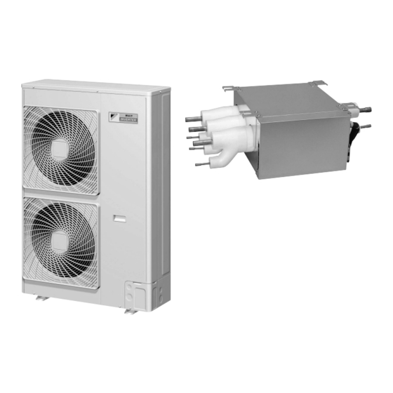
- Page 2 Service Manual Removal Procedure Outdoor Unit Cooling Only Heat Pump RMKS112LV1A RMXS112LV1A RMKS140LV1A RMXS140LV1A RMKS160LV1A RMXS160LV1A RMXS48LVJU BP Unit BPMKS967A2 BPMKS967A3 BPMKS048A2U BPMKS049A3U...
-
Page 3: Table Of Contents
Si181296_A Table of Contents 1. Outdoor Unit....................2 1.1 Outer Panels ....................2 1.2 PCBs / Electrical Components ..............4 1.3 Outdoor Fans / Fan Motors ..............12 1.4 Thermistors ....................13 1.5 Electronic Expansion Valves / Peripheral Equipments......14 1.6 Four Way Valve..................17 1.7 Compressor....................18 2. -
Page 4: Outdoor Unit
Outdoor Unit Si181296_A 1. Outdoor Unit Outer Panels Warning Be sure to wait for 10 minutes or more after turning off all power supplies before disassembling work. Step Procedure Points Remove the 8 screws It is possible to remove only Top panel and remove the top the front panel (2) without... - Page 5 Si181296_A Outdoor Unit Step Procedure Points The outdoor unit has 2 U.S. model: discharge grilles. The front panel (1) has 2 air Remove the 4 screws outlet protection nets. To and unfasten the 4 detach an air outlet hooks to remove a protection net, remove the 4 Discharge discharge grille.
-
Page 6: Pcbs / Electrical Components
Outdoor Unit Si181296_A PCBs / Electrical Components Warning Be sure to wait for 10 minutes or more after turning off all power supplies before disassembling work. Step Procedure Points 1. Remove the terminal M5(2) × 12 Terminal cover (upper) cover (The U.S. models only). - Page 7 Si181296_A Outdoor Unit Step Procedure Points 2. Remove the PCBs and M5(3) × 12 Terminal mounting plate electrical components. Remove the 2 screws of the terminal mounting plate. (Except the U.S. models.) (R12966) Remove the screw M5(3) × 12 above the electrical component assembly.
- Page 8 Outdoor Unit Si181296_A Step Procedure Points Cut off the 3 clamps. (R18066) (R18067) (R18068) Disconnect the relay connector for the reactor lead wire from each other. (R9225) Removal Procedure...
- Page 9 Si181296_A Outdoor Unit Step Procedure Points Disconnect the [X106A] [X107A]: fan motor connectors [X106A] [X106A] [X107A] [X107A]. (R12967) Release the fan motor lead wires from the hooks. (R9227) Release the lead wires of the solenoid valves and four way valve from the fixing plate and then remove the electrical component assembly.
- Page 10 Outdoor Unit Si181296_A Step Procedure Points Remove the 2 screws of the insulation sheet and then release the compressor lead wires (blue, red, white) and the relay wires between A1P and A3P (red, blue) from the hooks. (R9229) (R9230) 10 Remove the 2 screws M4 ×...
- Page 11 Si181296_A Outdoor Unit Step Procedure Points Cut the 2 clamps for the compressor lead wires. Cut the clamp for the relay wires from A3P to A1P (red, blue) and for Clamp for the relay wires from A3P to the earth / ground A1P and for the earth / ground (green).
- Page 12 Outdoor Unit Si181296_A Step Procedure Points 14 Disconnect the connectors [X66A] [X81A] [X5A]. [X66A] [X81A] [X5A] (R12970) 15 Disconnect the reactor lead wire connectors, compressor lead wire connector, and all the other connectors from the main PCB. [X66A] Compressor lead wire connector [X81A] [X5A]...
- Page 13 Si181296_A Outdoor Unit Step Procedure Points 16 Remove the screw at M4(2) × 12 the top of the electrical component assembly. (R9238) 17 Unfasten the 2 hooks at the rear side. Fixing plate for the Hook Electrical component mounting plate (R12972) 18 The figures in the right are PCB assembly.
-
Page 14: Outdoor Fans / Fan Motors
Outdoor Unit Si181296_A Outdoor Fans / Fan Motors Warning Be sure to wait for 10 minutes or more after turning off all power supplies before disassembling work. Step Procedure Points Remove the nuts and remove the outdoor fans. Outdoor fan Nut size : M8 13 mm (0.51 inch) -
Page 15: Thermistors
Si181296_A Outdoor Unit Thermistors Warning Be sure to wait for 10 minutes or more after turning off all power supplies before disassembling work. Step Procedure Points For the details of the Removal of the outdoor removal of the outdoor temperature thermistor temperature thermistor (R1T) (R1T), see the points... -
Page 16: Electronic Expansion Valves / Peripheral Equipments
Outdoor Unit Si181296_A Electronic Expansion Valves / Peripheral Equipments Warning Be sure to wait for 10 minutes or more after turning off all power supplies before disassembling work. Be careful not to get yourself burnt with the pipes and other parts that are heated by the gas brazing machine. - Page 17 Si181296_A Outdoor Unit Step Procedure Points The pressure sensor is Low pressure sensor (S1NPL) equipped with a gauge port with check valve. Therefore, when loosening the nut, refrigerant leak stops. (R12977) Disconnect the lead wires of the high pressure switch. High pressure switch (S1PH) (R12978) Remove the screw and...
- Page 18 Outdoor Unit Si181296_A Step Procedure Points Heat up and disconnect Electronic the brazed part of the expansion valve (main) electronic expansion valve. Electronic expansion valve (subcooling) (R12981) Heat up and disconnect the brazed part of the high pressure switch. Brazed part High pressure switch (R13062) Heat up and disconnect...
-
Page 19: Four Way Valve
Si181296_A Outdoor Unit Four Way Valve Warning Be sure to wait for 10 minutes or more after turning off all power supplies before disassembling work. Be careful not to get yourself burnt with the pipes and other parts that are heated by the gas brazing machine. -
Page 20: Compressor
Outdoor Unit Si181296_A Compressor Warning Be sure to wait for 10 minutes or more after turning off all power supplies before disassembling work. Be careful not to get yourself burnt with the pipes and other parts that are heated by the gas brazing machine. - Page 21 Si181296_A Outdoor Unit Step Procedure Points Remove the terminal cover with a flat screwdriver. Terminal cover (R9265) Disconnect the terminals of the compressor. Blue: W White: V Red: U (R12985) Remove the sound insulation for the compressor. (R9267) Remove the crankcase Pull the spring to release the heater at the lower of catch.
- Page 22 Outdoor Unit Si181296_A Step Procedure Points Remove the 3 nuts of You can see the rear side the compressor. nut when the lower discharge grille is removed. Remove the nuts in view first. (R9269) Cut off the suction pipe, discharge pipe and unloader pipe of compressor with a pipe cutter (3 places).
-
Page 23: Bp Unit
Si181296_A BP Unit 2. BP Unit PCB Assembly Warning Be sure to wait for 10 minutes or more after turning off all power supplies before disassembling work. Step Procedure Points Remove the 4 screws The PCB is waterproof with and remove the resin. - Page 24 BP Unit Si181296_A Step Procedure Points Disconnect all the relay cables. (Q0502) Remove the 2 screws PCB assembly and remove the PCB assembly. (R12990) Removal Procedure...
-
Page 25: Electronic Expansion Valve Coils
Si181296_A BP Unit Electronic Expansion Valve Coils Warning Be sure to wait for 10 minutes or more after turning off all power supplies before disassembling work. Step Procedure Points Detach the clamp of the wire harnesses. (R9272) (Q0509) Remove the 4 screws and remove the electrical component mounting plate. - Page 26 BP Unit Si181296_A Step Procedure Points Remove the sealing Sealing material materials of the pipe insulation sleeves. (R12994) (Q0513) Remove the putty. Electronic expansion valve coils for room A for room B for room C (R12993) Cut off the clamps and pull out the electronic Clamp expansion valve coils.
- Page 27 Revision History Month / Year Version Revised contents 12 / 2012 Si181296 First edition 04 / 2013 Si181296_A Model addition: RMXS48LVJU, BPMKS048A2U, BPMKS049A3U...
- Page 28 Improper installation can result in water or refrigerant leakage, electrical shock, fire or explosion. Use only those parts and accessories supplied or specified by Daikin. Ask a qualified installer or contractor to install those parts and accessories. Use of unauthorised parts and accessories or improper installation of parts and accessories can result in water or refrigerant leakage, electrical shock, fire or explosion.
Need help?
Do you have a question about the RMKS112LV1A and is the answer not in the manual?
Questions and answers