
Related Manuals for Daikin DM AHU


Summary of Contents for Daikin DM AHU
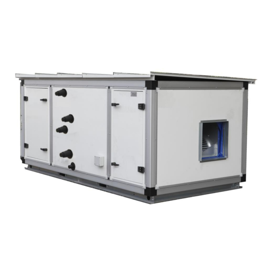
- Page 1 MANUAL INSTALLATION OPERATION MAINTENANCE Double Skin Modular Air Handling Unit MODELS DM AHU DS AHU AHUR VRV AHU VER: O-AHU01-DEC20-15 The design and construction are subject to change without any notice for future improvement.
- Page 2 Table of Contents 1. General ........................1 2. Shipment ........................1 3. Handling / Rigging ......................2 4. Storage ........................2 5. Assembly and Installation ....................2 6. Commissioning and Operation ..................12 7. Maintenance ....................... 14 8. Trouble Shooting......................16 9.
- Page 3 3. Handling / Rigging Air handling units can be delivered as separate section or completely assembled. To prevent damage to unit cabinet, a specific lifting method for offloading the units is recommended as shown in Figure 1. The spreader bars must be in position to prevent straps or cables from rubbing the frame panel.
- Page 4 5.2 Foundation Adequate space should be left around the unit for coils & drainage piping, filter replacement, maintenance. (See Figure 3). If site access space for coil is Figure 5 – Cabinet Section Joint not follow recommendation, AHU need to dismantle for coil replacement.
- Page 5 WARNING CABINET SECTION JOINTS ARE INTENDED LIFTING PURPOSE AND PULLING CABINET FROM DISTANCE JOIN SECTION TOGETHER. When the cabinets are penta-post to penta-post arrangement or joining two sections with different cabinet width, then below type of section joints will be provided.
- Page 6 8 and 10 in Figure 16 and Item 2, 3, 6, 9 in Figure 17 will be supply by factory. Refer to Installation and Operation manual Figure 12 – Removing of transport bracket of “EKEQMCBAV3 / EKEQFCBA – Option kit for combination of Daikin condensing units with handling units” further instructions.
- Page 7 IT IS ESSENTIAL TO HOLD THE Outdoor Air Series VRV AHU CONNECTOR / PIPE WITH TOOLS WHILST APPLYING COUNTER FORCE TO TIGHTEN THE JOINT. (See Figure 18) Figure 17- Outdoor Air Series VRV AHU Unit Figure 18 – Coil header connection method Outdoor unit Control box Air Handling unit...
- Page 8 the end panel of the coil section. All IMPORTANT connections are labeled on the end panel. CAREFULLY READ THROUGH control equipment, follow MANUFACTURING INSTRUCTION recommendations from the manufacturer APPLING ANTI-FREEZE regarding the types, sizing and installation SOLUTION. SOME PRODUCTS of equipment. Hot water coils are not WILL HAVE DIFFERENT FREEZING recommended to be used with entering air POINT IN ITS NATURAL STATE...
- Page 9 All installation and management activities must be carried out by qualified personnel. Refer to the specific wiring diagram and electrical component manual are attached with product before electrical installation. Site contractor shall termination at site for wiring connection between components that located at different AHU sections and delivered Figure 22 –...
- Page 10 Figure 26 – Belt deflection distance Figure 24 – Alignment of belt pulley Figure 25 – Belt tensioning Table 1 - Belt Tensioning Force Deflection Force (N) Pulley Belt Section Initial Fitting Retension Diameter <70 71-90 91-125 <100 101-140 141-200 <160 161-224 225-355...
- Page 11 87.29 104.58 124.69 141.69 159.78 157.92 2.25 86.20 103.36 123.60 140.60 158.33 156.29 85.11 102.13 122.51 139.51 156.88 154.65 2.75 84.02 100.90 121.42 138.42 155.43 153.02 82.93 99.68 120.33 137.33 153.98 151.38 3.25 98.45 119.24 136.24 152.52 149.75 97.22 118.15 135.15 148.11 3.75...
- Page 12 5.10. Ductwork Connections to unit cabinet are made by site drilling into the frame on the unit inlet or fan discharge collar. This should be load-free toward cabinet collar when initial positioned. Compliance with the Codes of Practice in duct assembly and acoustic layout are necessary to ensure the best possible performance of the unit whilst avoiding excessive pressure loss in the duct system...
- Page 13 5.11 Assembly of Complete Knock WARNING Down Unit (CKD) DO NOT HEAT ANY PART ON DX COIL IF REFRIGERANT STILL IN Due to container size constrain, some air THE SYSTEM. HEATING UP WILL handling units are packed in unassembled CAUSE DANGER HIGH condition - CKD method.
- Page 14 6.1.3 Fan Array 6.1.6 Damper & Filters Fan array is available for EC plug fan. Ensure fans control Check all dampers are operating correctly simultaneously and with same speed. as per design. Fans running at unequal speeds can result Make sure all filter media are installed in uneven airflow that cause performance, correct airflow direction.
- Page 15 CAUTION HIGH AIR TEMPERATURE IN FAN SECTION CAUSE MOTOR OVERHEAT DAMAGE. DRAW-THROUGH AIR HANDLERS, ADJUST DISCHARGE TEMPERATURE OF THE HEATING SECTION NOT TO EXCEED 104 6.4 Fan Operating Limits The fan operating limits for forward curve Figure 35 - Wiring Diagram with Neutral and airfoil fan are shown on the Table 3.
- Page 16 Check that vibration isolator mounts are functioning well. 7.3 Coil Section Inspect for any obstructions or blockages Periodic cleaning of coils is required. Dirty at air intakes and discharges. coils have tendency to increase airside Check fan bearings are secured and no pressure drops and reduce cooling/heating undue noise by observe/listen using metal efficiency.
- Page 17 ● Excessive vibration Check / Resolve ● Flexible connection Check / Tighten ● Vibration isolator Check / Tighten ● Intake air not obstruct Check / Clear ● Coil Section Fin block Check / Clean ● Frost protection Check / Apply ●...
- Page 18 b) Overload motor. connection. c) Low line voltage. b) Reduce system load. d) Over tensioned belts. c) Check supplied voltage within motor e) Misalign drive. voltage range. d) Adjust belt tension. e) Re-align drive. Motor overheats a) Overloaded motor. a) Reduce load or replace larger motor. b) Motor Fan dirty/ damage.
- Page 19 9. Appendix 9.1 Assembly of heat wheel 1. Heat wheel unit bottom section has already assembled with heat wheel support assembly and heat wheel baffle bottom when delivered. 2. Placed the baffle centre to the penta-post / centre-post or panel. 3.
- Page 20 AHU Commissioning Check Sheet General Information Project Unit Name Unit Model Unit Serial Number Installation Date Commissioning Date Initial Checking (Pre-start Up) A) Fan Section Are all fasteners tightened? Answer: Motor winding Resistances. U1-U2: __________ V1-V2: __________ W1-W2: __________ Motor Megger Test. U-Ground: __________ V-Ground: __________ W-Ground: _________ Are all electrical connections tight and of correct wiring? Answer:...
- Page 21 B) Coil Section No construction debris or foreign material left inside AHU. Answer: Is the condensate drain trapped properly? Answer: Are pipe connections to coil header correct? Answer: Ensure good sealing around the coil header and drain pipe externally. Answer: C) Others Make sure all dampers in AHU or ducting (if applicable) are in open position.
Need help?
Do you have a question about the DM AHU and is the answer not in the manual?
Questions and answers