
Related Manuals for Daikin OptiLine FSG


Summary of Contents for Daikin OptiLine FSG
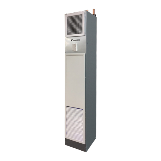
- Page 1 Installation, Operation and Maintenance IM 1272 Group: Fan Coils Part Number: 910243712 Date: July 2018 OptiLine Vertical Stack Fan Coil ™ Model FSG...
-
Page 2: Table Of Contents
Table of Contents Table of Contents Introduction . . . . . . . . . . . . . . . . . . . . . . . . . . . . . . . . . . 3 Troubleshooting . -
Page 3: Introduction
Introduction Introduction General Safety Information CAUTION NOTICE Sharp edges and coil surfaces are a potential injury hazard. Avoid contact The manufacturer’s warranty does not cover any damage or defect to with them. the air conditioner caused by the attachment or use of any components, accessories or devices (other than those authorized by the manufacturer) This manual contains the installation and operating instructions into, onto, or in conjunction with the air conditioner. -
Page 4: Design And Take-Off Precautions
Make Unless otherwise requested by the customer at the time of allowance for the 1" flange around the grille. Call Daikin at the shop drawing approval, the cabinet insulation is left intact,... -
Page 5: Installation
Daikin does not assume any responsibility for this procedure. It is stressed that the component manufacturer’s Daikin does not advise on the location or method of anchoring as this is recommended procedures be strictly followed. the responsibility of the engineering company retained to design the riser system. - Page 6 Installation Drywall Installation Supply Air Grille Installation The fan coil model series “FSG” has a cabinet which is The grille is a snap-in fit into the collar on the unit. If the unit designed to be furred-in. Drywall can be directly attached to has a ducted supply, side supply air grilles are provided with a the cabinet or the unit can be framed.
-
Page 7: Maintenance
Maintenance Maintenance Annually WARNING Warnings indicate potentially hazardous situations, which can result in (before the start of the cooling season) property damage, severe personal injury, or death if not avoided. • Remove the return air/access panel from the wall. Remove the two sheet metal screws which secure the CAUTION panel that shields the fan assembly. -
Page 8: Operating Instructions
Operating Instructions Operating Instructions Figure 1: EVO 3 Spd Fan CFM Adjustment Board CAUTION Equipment damage due to loose fasteners represents improper start-up and equipment abuse. It is not covered by the warranty. Rotate dial clockwise to increase Turn ON the disconnect switch located behind the fan max CFM or counter clockwise to decrease . -
Page 9: Sequence Of Operation
Operating Instructions Sequence of Operation 2-Pipe Heating/Cooling Units 2-Pipe Heating/Cooling Total Electric Heat Unit The control valve is activated by the cool and heat outputs from the thermostat which are connected to an aquastat. On a call The control valve and electric heat relay are activated by the for cooling from the thermostat and the water temperature is cool and heat outputs of the thermostat. -
Page 10: Troubleshooting
Troubleshooting Troubleshooting Control Valve Fails to Operate • 2-Pipe valve control heating/cooling units • 2-Pipe valve control heating/cooling auxiliary heat units Check the voltage from the thermostat, if no voltage, replace • 2-Pipe valve control heating/cooling with total electric the thermostat. If 24 volts or a DC voltage for modulating heat units valves is present, replace the actuator. -
Page 11: Startup Check List
Startup Check List Startup Check List Receiving & Inspection Unit Start-up … Unit received undamaged … Check for free and proper fan rotation … Unit received as ordered … Record electrical supply voltage and amperage … Check all wiring for secure connections Handling &... -
Page 12: Wiring Diagrams
Wiring Diagrams Wiring Diagrams Figure 4: 2-pipe Changeover plus Electric Heat, 120 Volt, 250 mm IM 1272 • OPTILINE VERTICAL FAN COILS www.DaikinApplied.com... - Page 13 Wiring Diagrams Figure 5: 2-pipe, Changeover plus Electric Heat, 208 Volt, 250 mm www.DaikinApplied.com IM 1272 • OPTILINE VERTICAL FAN COILS...
- Page 14 Wiring Diagrams Figure 6: 2-Pipe, Cooling Only, 120 Volt, 280 mm IM 1272 • OPTILINE VERTICAL FAN COILS www.DaikinApplied.com...
- Page 15 Wiring Diagrams Figure 7: 4-Pipe, 277 Volt, 310 mm www.DaikinApplied.com IM 1272 • OPTILINE VERTICAL FAN COILS...
-
Page 16: Addendum
Addendum Addendum Programmable Digital On–Off Valve and Modulating Fan Control Thermostats Figure 8: Front and Back View of TE226 – 24 Vac Thermostat Front Back Table 3: TE226 Components Item Description Display temperature and working status MODE button Access to user and engineer menu and for setting confirmation or change ºC/ºF unit if pressed for over 3 seconds FAN button Toggle to change Fan mode: Auto or Continuous UP &... - Page 17 Addendum Installation Mounting on electric box Figure 9: Wiring Diagram for TE226 – 24Vac Thermostat 1. Separate backplate from the controller by loosing the cover screw. 2. Align the mounting holes on the screw holes of the electric box (applicable to 65 × 65 or US standard box). 3.
- Page 18 Addendum Operation User Mode Operation MODE The first tier of operation includes the following settings to operate (Figure 2): 1. Power switch “ON” or “OFF” to start/stop the System. 2. After the switching “ON”, press any button to start the User Mode operation.
- Page 19 Addendum Figure 10: User Mode Operation Sequence Figure 11: Overview for the Settings of Clock and Programmable Schedules Press MODE, FAN, or POWER button to escape anytime during setting. MODE www.DaikinApplied.com IM 1272 • OPTILINE VERTICAL FAN COILS...
- Page 20 Addendum Figure 12: Detailed State Diagram for Clock Setting IM 1272 • OPTILINE VERTICAL FAN COILS www.DaikinApplied.com...
- Page 21 Addendum Figure 13: Detailed State Diagram for Schedule Setting Press “Mode” button to select (day shows steadily)/ deselect (day flash). Press MODE button to Press MODE button to Press MODE button to toggle Cooling/ Heating toggle Cooling/ Heating toggle Cooling/ Heating Set points Set points Set points...
- Page 22 Addendum Table 6: DefaultSetPointforProgrammableSchedules COOL Sch.1 6:00 6:00 6:00 6:00 6:00 6:00 6:00 78°F 78°F 78°F 78°F 78°F 78°F 78°F Sch. 2 8:00 8:00 8:00 8:00 8:00 8:00 8:00 85°F 85°F 85°F 85°F 85°F 85°F 85°F Sch. 3 18:00 18:00 18:00 18:00 18:00...
- Page 23 Addendum Control Actions MODE ON-OFF Valve Controls When Cooling or Heating is on, a “Running (Gear) ” icon will be shown on the LCD. Figure 14: Cooling and Heating Control, Auto Changeover, Dead band Option = 0 Figure 15: Cooling and Heating Control, Auto Changeover, Dead band Option = 1 www.DaikinApplied.com IM 1272 •...
- Page 24 Addendum Fan Controls Special Notes 1. Fan Output Adjustment: Fan output can be set to 1. Fan bar will be shown according to the fan output when minimum adjustment (AO2 Low (E7)) from 0-5 Vdc reaches low speed, medium speed or 100% of max and to maximum adjustment (AO2 High (E8)) from output.
- Page 25 Addendum Engineer Mode Operation This mode is highly suggested to be operated bytrained engineers because it is related to system parameters that will affect the control results. To operate: 1. Press UP and DOWN buttons for over 5 seconds to enter into engineer mode.
- Page 26 Addendum Table 7: Engineer Mode Menu Item Descriptions °C Type °F Type Item Mnemonic Description Step Default Range Default Range Dead band offset 0~10.0 0~18.0 0.5 (°C/°F) Unoccupied (ESI) Cooling ESIC 28.0 25.0~35.0 82.0 77.0~95.0 1.0(°C/°F) Set Point Unoccupied (ESI) Heating ESIH 15.0 10.0~22.0...
- Page 27 Addendum °C Type °F Type Item Mnemonic Description Step Default Range Default Range 0: N.O. dirH Heating Valve N.C./N.O. Setting 1: N.C. 0: DB is aligned to Cooling SP dbOP Dead band Options 1: SP is in the middle of DB tESt Self-Diagnostic Reset All Parameters to Factory...
- Page 28 Daikin Applied Training and Development Now that you have made an investment in modern, efficient Daikin equipment, its care should be a high priority. For training information on all Daikin HVAC products, please visit us at www.DaikinApplied.com and click on Training, or call 540-248-9646 and ask for the Training Department.
Need help?
Do you have a question about the OptiLine FSG and is the answer not in the manual?
Questions and answers