Table of Contents
Advertisement
Quick Links
DAQ SERIES
COMMERCIAL AIR HANDLERS
Table of Contents
Important Safety Instructions ....................................2
Qualified of Workers ................................................3
A2L Warning and Minimum Room Area ....................3
System Service and Decommissioning .....................6
Product Identification ..................................................6
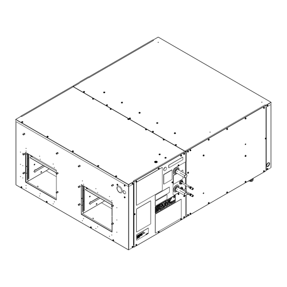
Product Description .....................................................6
Unit Inspection ................................................................7
Codes & Regulations ......................................................7
Replacement Parts ........................................................7
Pre-Installation Instructions .....................................7
Location ...........................................................................7
Ductwork .........................................................................8
Supply Ductwork and Flanges .................................8
Return Ductwork ........................................................8
Return Air Filters ......................................................8
Electric Heat ..................................................................8
Electrical Supply Wire and MOP ..............................10
Building Electrical Service Inspection .............10
Wire Sizing ................................................................10
Maximum Overcurrent Protection (MOP) .......... 11
Electrical Connections .............................................. 11
Supply Voltage .......................................................... 11
Air Handler Only (Non-Heat Kit Models) ............. 11
Heater Kit Models ..................................................... 11
Low Voltage Connections .......................................12
Heat Kit Installation ...................................................12
Refrigerant Lines ........................................................12
Tubing Preparation ...................................................12
Post Brazing ..............................................................12
Piping Size ...................................................................12
Charging Procedures ..............................................13
Airflow ...........................................................................13
Regular Maintenance ..................................................13
Refrigerant Detection System (RDS)....................14
IMPORTANT NOTE: DAQ models are suitable for
Upflow and Horizontal Installations only. do not
use for downflow Installations.
Do not bypass safety devices.
Our continuing commitment to quality products may mean a change in specifications without notice.
© 2024
IOD-1063A
08/2024
WARNING
19001 Kermier Rd. Waller, TX 77484
www.daikincomfort.com
INSTALLATION INSTRUCTIONS
Only personnel that have been trained to install, adjust,
service, maintenance or repair (hereinafter, "service")
the equipment specified in this manual should service the
equipment.
This equipment is not intended for use by persons
(including children) with reduced physical, sensory or
mental capacities, or lack of experience and knowledge,
unless they have been given supervision or instruction
concerning use of the appliance by a person responsible
for their safety.
Children should be supervised to ensure that they do not
play with the equipment.
The manufacturer will not be responsible for any injury
or property damage arising from improper supervision,
service or service procedures. If you service this unit, you
assume responsibility for any injury or property damage
which may result. In addition, in jurisdictions that require
one or more licenses to service the equipment specified in
this manual, only licensed personnel should service the
equipment. Improper supervision, installation, adjustment,
servicing, maintenance or repair of the equipment specified
in this manual, or attempting to install, adjust, service
or repair the equipment specified in this manual without
proper supervision or training may result in product
damage, property damage, personal injury or death.
WARNING
Advertisement
Table of Contents

Related Manuals for Daikin DAQ Series


Summary of Contents for Daikin DAQ Series
-
Page 1: Table Of Contents
INSTALLATION INSTRUCTIONS DAQ SERIES COMMERCIAL AIR HANDLERS Table of Contents Important Safety Instructions ........2 Qualified of Workers ..........3 A2L Warning and Minimum Room Area ....3 System Service and Decommissioning .....6 Product Identification ..........6 Product Description .............6 Unit Inspection ..............7 Codes & Regulations ............7 Replacement Parts ............7... -
Page 2: Important Safety Instructions
RDS Function ..............14 RDS Operation ............14 WARNING Recovery ..............14 Servicing Measures for the Refrigerant To prevent the risk of property damage, personal injury, or death, do not store combustible materials or use Detection System ............15 gasoline or other flammable liquids or vapors in the Troubleshooting Code ..........16 vicinity of this unit. -
Page 3: Qualified Of Workers
• Information about refrigerant detectors, including function, operation, and service measures. • Information about the concept of sealed components and sealed enclosures according to IEC 60079- 15:2010. • Information about the correct working procedures, including commissioning, maintenance, repair, decommissioning, and disposal procedures. WARNING The appliance shall be installed, operated and stored in a room with a floor area not less than the minimum room... - Page 4 ALTITUDE ADJUSTMENT FACTOR TO CALCULATE MINIMUM ROOM AREA The Indoor equipment mitigation requirements are calculated at sea level. For higher altitudes adjust the minimum room area specified on or near the Serial Plate or in the installation instruction manual by the corresponding altitude adjustment factor shown below.
-
Page 5: Accessory Installation
THE FOLLOWING INSTRUCTIONS ARE MANDATORY FOR A2L SYSTEMS AND SUPERSEDE OTHER INSTRUCTIONS WARNING ONLY BRAZING TECHNIQUES AND APPROVED MECHANICAL JOINTS SHOULD BE USED TO CONNECT REFRIGERANT TUBING CONNECTIONS. NON-APPROVED MECHANICAL CONNECTORS AND OTHER METHODS ARE NOT PERMITTED IN THIS SYSTEM CONTAINING A2L REFRIGERANT. APPROVED MECHANICAL JOINTS WILL BE DETAILED IN THE PRODUCT'S SPECIFICATION SHEETS. -
Page 6: System Service And Decommissioning
Empty recovery cylinders are evacuated The DAQ series is intended for use with a room thermostat. and, if possible, cooled before recovery occurs. A set of This thermostat is not supplied with this equipment. Only... -
Page 7: Unit Inspection
EQUIPMENT SUPPORT When installing this air handler in an enclosed area, such DAIKIN COMFORT TECHNOLOGIES as a garage/parking area, as with any carbon monoxide MANUFACTURING, L.P. producing device (i.e. and automobile, space heater, water 19001 KERMIER ROAD heater, etc.), insure that the area is properly ventilated. -
Page 8: Ductwork
• Closet/mechanical room When installing this unit in an area that may become wet, elevate the unit with a sturdy, non-porous material. Remove panel for vertical return. RETURN In installations that may lead to physical damage (warehouse, industrial sites, etc.), it is advised to install a protective barrier to prevent such damage. -
Page 9: Return Air Filters
Return Air Filters DAQ090 Temperature Rise Table (°F) Each installation must include a return air filter. This unit DAQ090 Temperature Rise Table (°F) - 7.5Ton is factory equipped with disposable return air filters. To ensure optimum performance, frequent filter replacement is advised. -
Page 10: Electrical Supply Wire And Mop
Electrical Supply Wire and MOP Percentage Max Voltage Deviation From Average CAUTION Voltage Unbalance = 100 x Average Voltage Example: L1 – L2 = 220 V FIRE HAZARD! L2 – L3 = 216 V To avoid the risk of property damage, personal injury or L1 –... -
Page 11: Maximum Overcurrent Protection (Mop)
MAXIMUM ALLOWABLE LENGTH IN FEET TO LIMIT Air Handler Only (Non-Heat Kit Models) VOLTAGE DROP TO 2% Supply wire is to be routed through conduit from the service disconnect box to the unit. The air handler is Minimum Circuit Ampacity (MCA) Wire Size equipped with a knockout suitable for ¾”... -
Page 12: Low Voltage Connections
Refrigerant Detection System (RDS) PCB Low Voltage Connection The wires from the heat kit are to be routed through the pipe nipple into the air handler electrical compartment. Ground See the “Electrical Connection” section of this manual for wiring details. Refrigerant Lines Supply Voltage WARNING... -
Page 13: Charging Procedures
Check condensing unit / heat pump instructions for CAUTION charging method. Airflow Applying too much heat to any tube can melt the tube. Torch heat required to braze tubes of various sizes must The blower motors are factory programmed with 5 torque be proportional to the size of the tube. -
Page 14: Clean Indoor Coil (Qualified Servicer Only)
Zone controller must be powered through a Daikin Zoning/ necessary to keep the finned areas free of debris. Any Accessory PCB to ensure that the Zoning Dampers open... - Page 15 LED Flashing Codes table. REFRIGERANT SENSORS for REFRIGERANT DETECTION SYSTEMS shall only be replaced with sensors specified by the manufacturer. If REFRIGERANT SENSOR requires replacement, please replace with Sensata R32 Sensor PN#RGD-00ML12 (Daikin PN#SER2A08012). LED STATUS MODE LED FLASHING PATTERN...
- Page 16 TROUBLESHOOTING CODE LED TROUBLESHOOT STATUS MODE DEFINITION LED FLASHING PATTERN RECOMMENDED ACTIONS NOTES Slow LED flashing pattern Normal Operation No faults to report. No actions needed. (2 seconds on and 2 seconds off) A technician will need to find where the refrigerant leak and In terms of the controls, no action is needed.
-
Page 17: Motor Removal
MOTOR REMOVAL NOTE: Disconnect and lockout/tagout any power source before performing motor/blower replacement. To service the motor: 1. Remove the split panel exposing the top of the blower housing. 2. Remove the panel on the side which the motor is being serviced. 3. -
Page 18: Blower Performance Tables
BLOWER PERFORMANCE TABLES 7.5 Ton LC Indoor Split System Models: DAQ090 BLOWER PERFORMANCE TABLES 7.5 Ton LC Indoor Split System Models: DAQ09033, DAQ09034 Up-Flow Horizontal SPEED single fan SPEED single fan (in H2O) (in H2O) SCFM SCFM 1,941 0.09 2,105 0.09 1,794 0.10... - Page 19 BLOWER PERFORMANCE TABLES 10 Ton LC Indoor Split System Models: DAQ120 BLOWER PERFORMANCE TABLES 10 Ton LC Indoor Split System Models: DAQ12033, DAQ12034 Up-Flow Horizontal SPEED single fan SPEED single fan (in H2O) (in H2O) SCFM SCFM 2,525 0.17 2,581 0.17 2,400 0.18...
-
Page 20: Wiring Diagram
WIRING DIAGRAM Wiring is subject to change. Always refer to the wiring diagram on the unit for the most up-to-date wiring. - Page 21 SPLITS LOW VOLTAGE DIAGRAM Wiring is subject to change. Always refer to the wiring diagram on the unit for the most up-to-date wiring.
- Page 22 THIS PAGE LEFT INTENTIONALLY BLANK...
- Page 23 THIS PAGE LEFT INTENTIONALLY BLANK...
-
Page 24: Customer Feedback
CUSTOMER FEEDBACK Daikin is very interested in all product comments. Please fill out the feedback form on the following link: https://daikincomfort.com/contact-us You can also scan the QR code on the right to be directed to the feedback page. Our continuing commitment to quality products may mean a change in specifications without notice.
Need help?
Do you have a question about the DAQ Series and is the answer not in the manual?
Questions and answers