Table of Contents
Advertisement
Quick Links
READ AND SAVE THESE INSTRUCTIONS
OPERATING
PN 62486
MANUAL
PUBLIX® FOOD BAR WITH HOT, COLD, SOUP & CABINETS for CONTAINERS, NAPKIN & TRASH
SEE
ACCOMPANYING
MANUAL
P/N 20-08064
FOR ALL WIRING
DIAGRAMS
PERTAINING TO
THESE CASES
PUBLIX® FOOD BAR
ISLAND CONFIGURATION
PUBLIX® FOOD BAR
IN-LINE CONFIGURATION
888 E. Porter Road · Muskegon, MI 49441 Phone: 231.798.8888 Fax: 231.798.4960 www.structuralconcepts.com
I:\Oper Manuals\CDR\4764-DP6470Q_DP1016H_DP1016R_DP812RG_DP610RG_CB6T_CB2CE_CB2C_62486.pub
Rev T Date: 8.23.2013
Advertisement
Table of Contents
Troubleshooting

Related Manuals for Structural Concepts Impulse 62486


Summary of Contents for Structural Concepts Impulse 62486
- Page 1 READ AND SAVE THESE INSTRUCTIONS OPERATING PN 62486 MANUAL PUBLIX® FOOD BAR WITH HOT, COLD, SOUP & CABINETS for CONTAINERS, NAPKIN & TRASH ACCOMPANYING MANUAL P/N 20-08064 FOR ALL WIRING DIAGRAMS PERTAINING TO THESE CASES PUBLIX® FOOD BAR ISLAND CONFIGURATION PUBLIX®...
-
Page 2: Table Of Contents
TABLE OF CONTENTS - PAGE #1 of 2 GENERAL CASE MATERIAL (APPLICABLE TO ALL CASES) TABLE OF CONTENTS ………………………………………………………………………………………………….. OVERVIEW / NSF® TYPE / COMPLIANCE / WARNINGS / PRECAUTIONS / WIRING ……..……...…….. ISLAND CONFIGURATION LAYOUT - EXPLODED VIEW / INSTALLATION OVERVIEW ……...……………… ... - Page 3 TABLE OF CONTENTS - PAGE #2 of 2 DISPLAY CASE #4: DISPLAY CASE #4: NAPKIN-UTENSIL-TRASH BIN END CAP MODEL CB6T.4764 …. DISPLAY CASE #5: DISPLAY CASE #5: REFRIGERATED SELF-SERVICE FOOD BAR END CAP MODELS DP610RE.4764 & DP610RGE.4764 …………………………………………………………………...….…. MODEL DP610RE.4764 / DP610RGE.4764 IN LINEUP / PULL-OUT STORAGE DRAWER .…….………..….. ...
-
Page 4: Overview / Nsf® Type / Compliance / Warnings / Precautions / Wiring
OVERVIEW / NSF® TYPE / COMPLIANCE / WARNINGS / PRECAUTIONS / WIRING / GFCI / WELLS OVERVIEW COMPLIANCE These Structural Concepts Impulse® cases are designed to Performance issues when in violation of applicable NEC, merchandise product at a range of temperature. federal, state and local electrical and plumbing codes are not ... -
Page 5: Island Configuration Layout - Exploded View / Installation Overview
ISLAND CONFIGURATION LAYOUT - EXPLODED VIEW / INSTALLATION OVERVIEW ISLAND CONFIGURATION LAYOUT - EXPLODED VIEW / INSTALLATION OVERVIEW Below illustration provides a perspective view of the food bar island layout. Follow the six (6) step-by-step installation procedure as sequentially listed below. ... -
Page 6: In-Line Configuration Layout - Exploded View (With Swappable Dp547Q.4764)
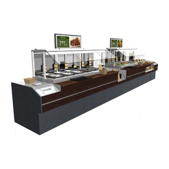
IN-LINE CONFIGURATION LAYOUT - EXPLODED VIEW (WITH SWAPPABLE DP547Q.4764) IN-LINE CONFIGURATION LAYOUT - EXPLODED VIEW Below illustration provides a perspective view of the food bar in-line configuration layout. See the previous page for a perspective view of the food bar island configuration layout. Hot Bar Model DP1016H.4764 Cold Bar Model DP1016R.4764 Trash/Napkin... -
Page 7: Installation: Case Removal From Skid / Line-Up
INSTALLATION: CASE REMOVAL FROM SKID / LINE-UP 1. Remove Case From Skid A. Fork Lift To lift case up for lift-truck forks to slide into position, use J-Bar Lift Tab (location #1 shown below) or Support Rung (location #2 shown below). -
Page 8: Installation, Continued: Frame Support Rails / Removable Front Panels
INSTALLATION, CONTINUED: FRAME SUPPORT RAILS / REMOVABLE FRONT PANELS 2. Frame Support Rails Note: Below illustration reflects underside of Soup Case. However Frame Support Rail Illustration below shows case with frame support instructions apply to all cases. rails at underside. Note: Though underside of soup case is shown, frame support layout is 3. -
Page 9: Display Case #1: Soup Bar Model Dp647Q.4764
DISPLAY CASE #1: SOUP BAR MODEL DP647Q.4764 Display Case #1 This section pertains only to Soup Bar Model DP647Q.4764 Model DP647Q.4764 (With Soup Signage Bar System) -
Page 10: Field Wiring Box / Auto-Fill Connection / Field Hookup Of Water Line
FIELD WIRING BOX / AUTO-FILL CONNECTION / WATER LINE FIELD HOOKUP 1. Field-Wire Box, Auto-Fill Connection to Remove screws from rear plate to access. Appropriate Receptacle Box Wiring to distribution blocks, main power switch, and heater dials are located in Power Distribution ... -
Page 11: Panel Removal / Wye Cleanout Tee, Solenoid Valve & Water Drain Field Hookup
PANEL REMOVAL / WYE CLEANOUT TEE, SOLENOID VALVE & WATER DRAIN FIELD HOOKUP 1. Front-Left Panel Must Be Removed to Access 3. Solenoid Valve / Field Hookup of Water Drain Removal of front-left panel will allow full access Caution! Only certified plumbers/mechanical to solenoid valve and water drain field hookup. -
Page 12: Vollrath® Modular Drop-In Reservoir W/Auto-Fill / Attaining Proper Water Levels
VOLLRATH® MODULAR DROP-IN RESERVOIR W/AUTO-FILL / ATTAINING PROPER WATER LEVELS 1. Modular Drop-In Auto-Fill Reservoir Control box ratings: 120V, 16W, NEMA 5-15R Vollrath® Modular Drop-In Auto-Fill Reservoir receptacle required. automatically maintains consistent water levels in hot See next page for illustrated parts breakdown. wells or soup wells. -
Page 13: Vollrath® Modular Drop-In Reservoir With Auto-Fill: Illust. Parts Breakdown
VOLLRATH® MODULAR DROP-IN RESERVOIR WITH AUTO-FILL: ILLUSTRAT. PARTS BREAKDOWN Sample Wells (Shown For Illustrative Modular Drop- Purposes Only). In Auto-Fill Hatco® Heated Soup Reservoir Wells Differ in Appearance. Recommended Water Level of 1/2”. See Previous Page for Instructions on Raising or Lower Level. -
Page 14: Start-Up & Operation [Soup Bar Model Dp647Q.4764]: Initial Start-Up / Purging
Heated Well. soup wells does NOT reach recommended levels, 4. Initial Startup: Heated Well Purging Procedure contact Structural Concepts Technical Service Department for guidance. Caution! Water Lines Must Be Purged at Initial Startup or Heated Wells May Overflow! >>... -
Page 15: Daily Step-By-Step Procedure [Soup Bar Model Dp647Q.4764]: Beginning / End Of Day
DAILY STEP-BY-STEP PROCEDURE [SOUP BAR MODEL DP647Q.4764]: BEGINNING / END OF DAY Daily Step-By-Step Procedure: Beginning and F. Also at end of day, flip Auto-Fill Switch to ‘Off’ End of Day position (or water will run all night)! To do so, press downward on the “O”... -
Page 16: Soup Wells/Soup Bowls & Lids/Napkin Dispensers/Supplies/Trash Drawers
SOUP WELLS / SOUP BOWLS & LIDS / NAPKIN DISPENSERS / SUPPLIES & TRASH DRAWERS Soup Utensil / Napkin / Supplies / Trash Bin Placement Case Rear Illustration below shows the various compartments designed to hold the following: Soup Wells (4 total) ... -
Page 17: Dispense-Rite Cup Dispenser Adjustment Instructions
DISPENSE-RITE CUP DISPENSER ADJUSTMENT INSTRUCTIONS DISPENSE-RITE® ADJ-1, ADJ-2 & ADJ-3 SERIES ADJUSTMENT INSTRUCTIONS FOLLOW THESE INSTRUCTIONS... -
Page 18: Soup Signage Bar System Instruction Sheet
SOUP SIGNAGE BAR SYSTEM INSTRUCTION SHEET Isometric View of Soup Signage Bar System Soup Signage Bar System Installed on Case 1. Sign and sign rails are shipped as one piece. 2. Place purchased frame onto sign. 3. Slide sign rails down into retainers. -
Page 19: Trash Bin Removal / Trash Dispenser Removal (For Cleaning Purposes)
TRASH BIN REMOVAL / TRASH CHUTE REMOVAL (FOR CLEANING PURPOSES) Trash Chute 1. Trash Bin Removal (one at each Trash bins are at left and right of case. end of case) Trash bags are removable from each trash bin. ... -
Page 20: Hatco® Heated Wells - Important Safety Information / Model Designation
HATCO® HEATED WELLS - IMPORTANT SAFETY INFORMATION / MODEL DESIGNATION... -
Page 21: Hatco® Heated Wells - Model Specifics / Electrical Rating Chart
HATCO® HEATED WELLS - MODEL SPECIFICS / ELECTRICAL RATING CHART Structural Concepts uses Hatco® Model HWB-7QTD on case DP6470Q.4764. Model HWB-7QTD... -
Page 22: Hatco® Heated Wells - Operation
HATCO® HEATED WELLS - OPERATION Caution! To avoid damaging Hatco® heated soup wells, carefully follow these instructions! -
Page 23: Troubleshooting - Hatco® Heated Wells
TROUBLESHOOTING - HATCO® HEATED WELLS TROUBLESHOOTING - HATCO® HEATED WELLS Standard and approved manufacturing oils may smoke up Operate unit without food product until smoke Heated wells are smoking. to 30 minutes during initial start-up. dissipates. This is a temporary condition. If unit is operating wet and is allowed to run Heated wells may have been Food is not consistently heating. -
Page 24: Hatco® Heated Wells - Cleaning Guidelines & Schedule
HATCO® HEATED WELLS - CLEANING GUIDELINES & SCHEDULE This unit has no “user-serviceable” parts. If service is required on this unit, contact Structural Concepts Technical Service Dept. See the TECHNICAL SERVICE CONTACT INFORMATION & WARRANTY INFORMATION section in is operating manual for specifics. -
Page 25: Hatco® Limited Warranty Information
HATCO® LIMITED WARRANTY INFORMATION... -
Page 26: Display Case #2: Hot Bar Models Dp1016H.4764, Dp1016Ho.4764, Dp812H.4764, Dp812Ho.4764, Dp610H.4764, Dp610Ho.476
DISPLAY CASE #2: HOT BAR MODELS DP1016H.4764, DP812H.4764 & DP610H.4764 Display Case #2 This section pertains only to Hot Bar Models DP58H.4764, DP58HO.4764, DP1016H.4764, DP1016HO.4764, DP812H.4764, DP812HO.4764, DP610H.4764 & DP610HO.4764 Model DP1016H.4764 Shown Above... -
Page 27: Field Wiring Box / Drains / Actuated Ball Valve & Switch / Power Distribution Access
FIELD WIRING BOX / DRAINS / ACTUATED BALL VALVE & SWITCH / POWER DISTRIBUTION ACCESS 1. Field Wiring Box, Heated Well Drains, 2. Power Distribution Access Caution! Risk of electric shock! Turn power off Actuated Ball Valve & Switch, Power Distribution Access and disconnect power source before accessing. -
Page 28: Field Hookup Of Water Line / Water Pressure Regulator
FIELD HOOKUP OF WATER LINE / WATER PRESSURE REGULATOR - MODEL DP1016H.4764 1. Water Line Field Hookup Connect This Water See photos below. Drain Pipe To Floor Caution! To prevent leakage, use care to assure proper hookup. Drain 2. -
Page 29: Start-Up And Operation [Hot Bar Models Dp1016H.4764, Dp812H.4764 & Dp610H.4764]
START-UP AND OPERATION [HOT BAR MODELS DP1016H.4764, DP812H.4764 & DP610H.4764] Merchandiser Start-Up and Operation 5. Daily Step-By-Step Procedure A. At beginning of day, verify that drain is closed. If it is 1. Power Up Case not, flip the Drain Control Switch to ‘Closed’ (see below). ... -
Page 30: Trash Bin Removal / Lights / Light Switch & Condensation Fan Switch Location
TRASH BIN REMOVAL / LIGHTS / LIGHT SWITCH & CONDENSATION FAN SWITCH LOCATION Removal of lamps: 1. Trash Bin Removal Rotate lamp (1/4-turn) to disengage (upper or Trash bins are at left and right of case. lower) pins/contacts from mounting sockets. Trash bags are removable from each bin. -
Page 31: Condensation Fans / Condensation Fan Filter
CONDENSATION FANS / CONDENSATION FAN FILTER 1. Condensation Fans 2. Condensation Fan Filter Depending upon environment, condensation on Each section of case (three total) has its own sneeze guards (caused by heat) pans could condensation fan filter. occur. -
Page 32: Condensation Fans - Access, Removal & Replacement Of Fans
CONDENSATION FANS - ACCESS, REMOVAL & REPLACEMENT OF FANS Access, Remove & Replace Fans 3. Disconnect plug from hole at customer left side of case to free up fans. 1. Remove fan cover screws (one screw at each 4. Remove fan panel screws (one at each end of end of fan cover). -
Page 33: Side Glass / Sneeze Guard Removal & Replacement
SIDE GLASS / SNEEZE GUARD REMOVAL & REPLACEMENT (PAGE #1 of 2) 1. Side Glass Removal 2. Sneeze Guard Removal & Replacement Caution! Hold glass firmly while removing retaining A. Lift top glass up and off (no screws required). screws! B. - Page 34 SIDE GLASS / SNEEZE GUARD REMOVAL & REPLACEMENT (PAGE #2 of 2) 2. Sneeze Guard Removal & Replacement, G. View shown of nut (1 of 3) now accessible after inner light housing has been dropped down. Continued H. Bolts (viewable after light shield has been removed) E.
-
Page 35: Hatco® Modular Built-In Insulated Heated Wells - Important Safety Info
HATCO® MODULAR BUILT-IN INSULATED HEATED WELLS - IMPORTANT SAFETY INFORMATION... -
Page 36: Hatco® Modular Built-In Insulated Heated Wells - Description / Elec Chart
Food pans, pan support bars and adapter tops are sold Guideline of Display Case to Hatco® Unit separately. >>> Structural Concepts Display Case DP1016H.4764 uses Hatco® Model HWBI-4MA. Note: The “M” and “A” of the models reflect the: >>> Structural Concepts Display Case DP610H.4764 uses ... -
Page 37: Hatco® Modular Built-In Insulated Heated Wells - Wiring Diagrams
HATCO® MODULAR BUILT-IN INSULATED HEATED WELLS - WIRING DIAGRAMS - PAGE #1A Model HWBI-4MA Models HWBI-4MA, 5MA and 6MA... - Page 38 HATCO® MODULAR BUILT-IN INSULATED HEATED WELLS - WIRING DIAGRAMS - PAGE #1B Model HWBI-4MA...
- Page 39 HATCO® MODULAR BUILT-IN INSULATED HEATED WELLS - WIRING DIAGRAMS - PAGE #2A Models HWBI-4MA, 5MA and 6MA...
- Page 40 HATCO® MODULAR BUILT-IN INSULATED HEATED WELLS - WIRING DIAGRAMS - PAGE #2B Models HWBI-4MA, 5MA and 6MA...
-
Page 41: Hatco® Modular Built-In Insulated Heated Wells - Installation
HATCO® MODULAR BUILT-IN INSULATED HEATED WELLS - INSTALLATION To Drain... -
Page 42: Hatco® Modular Built-In Insulated Heated Wells - Operation
HATCO® MODULAR BUILT-IN INSULATED HEATED WELLS - OPERATION... -
Page 43: Hatco® Modular Built-In Insulated Heated Wells - Troubleshooting Guide
HATCO® MODULAR BUILT-IN INSULATED HEATED WELLS - TROUBLESHOOTING GUIDE Standard and approved manufacturing oils may smoke up Operate unit without food product until smoke Heated wells are smoking. to 30 minutes during initial start-up. dissipates. This is a temporary condition. If unit is operating wet and is allowed to run Heated wells may have been Food is not consistently heating. -
Page 44: Hatco® Modular Built-In Insulated Heated Wells - Warnings & Cleaning Schedule
HATCO® MODULAR BUILT-IN INSULATED HEATED WELLS - WARNINGS & CLEANING SCHEDULE NOTE: This unit has no “user-serviceable” parts. If service is required on this unit, contact Structural Concepts Technical Service Dept. See the TECHNICAL SERVICE CONTACT INFORMATION & WARRANTY INFORMATION... -
Page 45: Hatco® Modular Built-In Insulated Heated Wells - Limited Warranty Info
HATCO® MODULAR BUILT-IN INSULATED HEATED WELLS - LIMITED WARRANTY INFORMATION... -
Page 46: Dp610R.4764, Dp610Rg.4764 & Dp58R.4764
DISPLAY CASE #3: “4764” MODELS DP1016R, DP812R, DP812RG, DP610RG, DP610R & DP58R Display Case #3 This section pertains to Refrigerated Salad Bar Models DP1016R.4764, DP812R.4764, DP812RG.4764*, DP610R.4764, DP610RG.4764* and DP58R.4764 *[Glycol Based Units] Note: Illustration Shown May Not Exactly Reflect Every Feature or Option of Your Particular Case Note: Center-Front Panel May Also Be Optional... -
Page 47: Field Wiring Box / Electrical Wires / Drain Location / Bohn® Refrigeration Unit
FIELD WIRING BOX / ELECTRICAL WIRES / DRAIN LOCATION / BOHN® REFRIGERATION UNIT 1. Field-Wiring Box, Electrical Wires (from Upper 2. Field Hookup of Refrigeration Line See illustration below. Section), and Drain Location Caution! Only certified electricians are to perform ... -
Page 48: Fluorescent Lights & Light Switch
FLUORESCENT LIGHTS & LIGHT SWITCH Light Fixtures & Light Switch Remove bulb by applying even pressure from back side at the bulb ends and pulling the Light fixtures are located at the underside of shelf remaining contact from sockets. assemblies. -
Page 49: Layout Of Models With Optional Refrigerated Drawer / Drawer Thermometer
LAYOUT OF MODELS WITH OPTIONAL REFRIGERATED DRAWER / DRAWER THERMOMETER 1. Layout of Models With Optional Refrigerated panel as well as electrical and plumbing layout. Drawer [Model DP610RG is Shown Below] 3. Thermometer Optional refrigerated drawer is on internal ... -
Page 50: Case Rear: Optional Refrigerated Drawer / Optional Removable Rear Panel
CASE REAR: OPTIONAL REFRIGERATED DRAWER / OPTIONAL REMOVABLE REAR PANEL Rear View of Models With Optional Refrigerated Should model have rear panel, it may be removed Drawer without screws. Simply lift rear panel up and off hooks. Models with optional refrigerated drawer may ... -
Page 51: Bohn® Refrigeration Unit - General Information / Troubleshooting / Nomenclature / Txv Valve Info / Parts / Sealant
BOHN® REFRIGERATION UNIT - GENERAL INFORMATION... - Page 52 BOHN® REFRIGERATION UNIT - TROUBLESHOOTING...
- Page 53 BOHN® REFRIGERATION UNIT - NOMENCLATURE / TXV VALVE INFO / PARTS / SEALANT Structural Concepts uses Bohn® Model VA-08-A on case DP1016R.4764...
- Page 54 DISPLAY CASE #4: NAPKIN-UTENSIL-TRASH BIN END CAP MODEL CB6T.4764 Display Case #4 This section pertains only to Trash / Napkin Cabinet Model CB6T.4764 1. Trash Bin Removal 2. Napkin Dispensers / Utensil Dispenser / Trash Dispenser Trash bins are at left and right of case. ...
- Page 55 DISPLAY CASE #5: “4764” REFRIG. SELF-SVC FOOD BAR END CAP MODELS DP610RE & DP610RGE Display Case #5 This section pertains only to Refrigerated Self-Service Food Bar End Cap Models DP610RE.4764 and DP610RGE.4764* *Glycol Based Unit] Model DP610RE.4764...
-
Page 56: Model Dp610Re.4764 / Dp610Rge.4764 In Lineup / Pull-Out Storage Drawer
MODEL DP610RE.4764 / DP610RGE.4764 IN LINEUP / PULL-OUT STORAGE DRAWER Line-up View of Model DP610RE.4764 [or DP610RGE.4764 if Glycol-Based Unit] Model DP610RE End Cap Pull-Out Storage Drawer [Non-Refrigerated] Pull-out storage drawer is at front of case. See illustration below. ... -
Page 57: Field Wiring Box / Electrical Wires / Drain / Refrig. / Fluorescent Lights & Switch
FIELD WIRING BOX / ELECTRICAL WIRES / DRAIN / REFRIG. / FLUORESCENT LIGHTS & SWITCH 1. Field-Wiring Box, Electrical Wires (from Upper Note: Warranty will be void if claims arise from Section), and Drain Parts & Location negligence, misuse of goods, extreme ... -
Page 58: Display Case #6: Napkin-Trash End Cap Model Cb1.5T.4764
DISPLAY CASE #5: NAPKIN-TRASH END CAP MODEL CB1.5T.4764 Display Case #6 This section pertains only to Napkin-Trash End Cap Model CB1.5T.4764 Napkin Dispensers / Trash Dispenser See illustration below for location of items See previous page for general details as it relates to TRASH BIN REMOVAL / Napkin TRASH CHUTE REMOVAL and... -
Page 59: Display Case #7: Container Cabinets Models Cb2C.4764 & Cb2Ce.4764
DISPLAY CASE #6: CONTAINER CABINETS MODELS CB2C.4764 & CB2CE.4764 Display Case #7 This section pertains only to Container Cabinet Models CB2C.4764 & CB2CE.4764 SEE ACCOMPANYING MANUAL P/N 20-08064 FOR ALL Note: WIRING DIAGRAMS PERTAININGTO THESE CASES. Container Cabinets Models CB2C.4764 & CB2CE.4764 are identical. -
Page 60: Electrical Hookup / Electrical Layout
ELECTRICAL HOOKUP / ELECTRICAL LAYOUT [MAY SLIGHTLY DIFFER DEPENDING UPON LINEUP] Electrical Hookup shown below is to Model CB2CE.4764 1. Front Panel is to be lifted up and off. 2. Use flat-head or Phillips™ screwdriver to remove screws holding front cover in place. 3. -
Page 61: Utensil-Tray-Plate & "To-Go" Box Layout / Signage Placement & Removal
UTENSIL-TRAY-PLATE & “TO-GO” BOX LAYOUT / SIGNAGE PLACEMENT & REMOVAL 1. Utensil-Tray-Plate & “To-Go” Box See illustration below-left for location. All utensil storage pieces are shipped loose and may be repositioned on cabinet as desired. 2. Signage Placement, Adjustment & Removal ... -
Page 62: Cleaning Schedule - General
CLEANING SCHEDULE - GENERAL (DAILY “D” / WEEKLY “W” / MONTHLY “M”) Cleaning Task Clean Case Clean wood, laminate and painted surfaces (including shelves) with a warm Exterior soap and water solution and soft cloth. Never use wire cloth or abrasive cleaners on case. -
Page 63: Cleaning Procedure - Cambria® Natural Quartz Surface
CLEANING PROCEDURE - CAMBRIA® NATURAL QUARTZ SURFACE Overview - Cambria® Natural Quartz Surface Cambria is created from pure natural quartz, an extremely hard stone crystal, mined directly from the earth. In fact, quartz is the hardest non-precious stone to be found in the earth's surface. -
Page 64: Troubleshooting - General Case Issues
TROUBLESHOOTING - GENERAL CASE ISSUES CONDITION TROUBLESHOOTING - GENERAL CASE ISSUES System Is Not Check that the utility power is on. Operating Check that the on/off switch is on. Check that the temperature control dial is not turned all the way down. Check the circuit breaker box for tripped circuits. - Page 65 For additional technical information and service, see the TECHNICAL SERVICE page in this For additional technical information and service, see the TECHNICAL SERVICE page in this manual for manual for instructions on contacting Structural Concepts’ Technical Service Department. instructions on contacting Structural Concepts’ Technical Service Department. ...
-
Page 66: Technical Service Contact Information & Warranty Information
LIMITED WARRANTY All sales by Structural Concepts Corporation (SCC) are subject to the following limited warranty. “Goods” refers to the product or products being sold by SCC. Warranty Scope: Warranty is for equipment sold in the United States, Canada, Mexico and Puerto Rico. Equipment sold elsewhere may carry modified warranty.
Need help?
Do you have a question about the Impulse 62486 and is the answer not in the manual?
Questions and answers