Table of Contents
Advertisement
M O B I L E
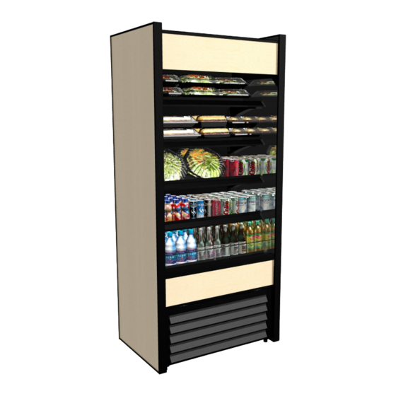
OASIS REFRIGERATED "BOX CASES" / SELF-CONTAINED & REMOTE / OPTIONAL
SECURITY COVERS / TOP-MOUNTED CONDENSER PKGS ON CERTAIN MODELS
Model B32
Model B8832 (With Optional
Roll-Down Security Cover)
* See Next Page For List of Models Covered
By This Manual. Note: This Manual May Also
Be Applicable To Models Not Listed Herein.
888 E. Porter Road · Muskegon, MI 49441 Phone: 231.798.8888 Fax: 231.798.4960 www.structuralconcepts.com
I:\Oper Manuals\Oasis\B22_B32_B36_B42_B42C_B47_B59_B62_B71_B82_B88_B92_54110.pub
READ AND SAVE THESE INSTRUCTIONS
INSTALLATION &
OPERATING MANUAL
SCC P/N 54110
S E R I E S
Model B42C
Model
B6632SC.6241
Model B4732 (With Optional
Roll-Down Security Cover)
Model
B22.6817
Important!
If You Are
Adjoining Cases,
See Synchronous
Defrost Connection
Instructions On Page 8
AND Adjoinment
Instructions on
Page 9 Of This
Operating Manual.
Model B43C
Model B5932TM.6785
(Similar To B4732TM.6785)
(Top-Mounted Condenser
Pkg. / Underside Pump) /
Optional Rear Doors
Rev AI Date: 12.20.2017
Advertisement
Table of Contents
Troubleshooting

Related Manuals for Structural Concepts Oasis Mobile B4732


Summary of Contents for Structural Concepts Oasis Mobile B4732
- Page 1 READ AND SAVE THESE INSTRUCTIONS INSTALLATION & Important! OPERATING MANUAL If You Are SCC P/N 54110 M O B I L E S E R I E S Adjoining Cases, See Synchronous Defrost Connection OASIS REFRIGERATED “BOX CASES” / SELF-CONTAINED & REMOTE / OPTIONAL Instructions On Page 8 SECURITY COVERS / TOP-MOUNTED CONDENSER PKGS ON CERTAIN MODELS AND Adjoinment...
-
Page 2: Table Of Contents
TABLE OF CONTENTS / MODELS TO WHICH THIS MANUAL IS APPLICABLE OVERVIEW / TYPE / COMPLIANCE / WARNINGS / PRECAUTIONS / WIRING / PLUGS ……………………….. INSTALLATION: CASE REMOVAL (VIA LEVELERS & CASTERS) …….……………………………………..…….. INSTALLATION, CONTINUED: POSITIONING & ALIGNING CASE / ADJUSTING LEVELERS .…………..…….. INSTALLATION, CONTINUED: OPTIONAL SECURITY COVER INSTRUCTIONS ……………………….…….…. -
Page 3: Overview / Type / Compliance / Warnings / Precautions / Wiring / Plugs - Page 1 Of 2
OVERVIEW exceed 80 °F (27 °C) and 55% maximum humidity. These Structural Concepts merchandisers are If unsure if your unit is Type I or II, see tag next to serial designed to merchandise packaged products at 41 °F label. - Page 4 OVERVIEW / TYPE / COMPLIANCE / WARNINGS / PRECAUTIONS / WIRING / PLUGS - PAGE 2 of 2 PRECAUTIONS WIRING DIAGRAM This sheet contains important precautions to prevent Each case has its own wiring diagram folded and in its damage to unit or merchandise.
-
Page 5: Installation: Case Removal (Via Levelers & Casters)
INSTALLATION: CASE REMOVAL (VIA LEVELERS & CASTERS) 1. Remove Case From Skid (Levelers) Remove shipping brace that may be securing case to skid. Support case to prevent tipping. Caution! Levelers can be damaged if case hits floor with heavy force! ... -
Page 6: Installation, Continued: Positioning & Aligning Case / Adjusting Levelers
INSTALLATION, CONTINUED: POSITIONING & ALIGNING CASE / ADJUSTING LEVELERS 3. Position & Align Alongside Other Cases Before adjusting levelers, make certain that the case is in proper position and, if required, aligned with adjoining case(s). This may require the repositioning of the case you are installing or the already positioned case(s). 4. -
Page 7: Installation, Continued: Optional Security Cover Instructions
INSTALLATION, CONTINUED: OPTIONAL SECURITY COVER INSTRUCTIONS C. Check that the lock properly rotates its locking 5. Optional Security Cover Instructions mechanism into support angle slot (at upper Caution! Security Cover MUST Be Placed On area). OUTSIDE of Acrylic Air Deflector and INSIDE >... -
Page 8: Installation, Continued: Synchronous Defrost Connection (Optional)
INSTALLATION, CONTINUED: SYNCHRONOUS DEFROST CONNECTION (OPTIONAL) 6. Synchronous Defrost Connection (Optional) Adjoined cases MUST HAVE its synchronous defrost plugs connected. See wiring diagram accompanying case. Attention! Sample Adjoined cases have Synchronous Defrost Plug (Typ.) synchronous defrosts. Synchronous Defrost ... -
Page 9: Installation, Continued: Adjoinment Instructions
INSTALLATION, CONTINUED: ADJOINMENT INSTRUCTIONS #3 holes are accessible after removing decking. 7. Overview / Silicone and Buty Application #4-6 holes are accessible after removing front panel. Sealant Overview: #7-9 holes are accessible after removing rear panel. Warranty is void if improper sealant is used. ... -
Page 10: Front Grille Removal / Condenser Package / Overflow Pan / Main Power Switch
FRONT GRILLE REMOVAL / CONDENSER PACKAGE / OVERFLOW PAN / MAIN POWER SWITCH Thumbscrews 1. Removable Front Grille Front grille can be removed/replaced via thumbscrew and magnet removal method (shown top-right) OR slot and hook method (shown lower-right). Thumbscrew Thumbscrew 2. -
Page 11: Evaporator Coil Fan Discharge / Txv (Thermostatic Expansion Valve)
EVAPORATOR COIL FAN DISCHARGE / TXV (THERMOSTATIC EXPANSION VALVE) 1. Evaporator Coil Fan Discharge When Main Power Switch is turned on, refrigeration assembly will energize (see CASE START-UP & REFRIGERATION ASSEMBLY ACCESS section). Evaporator coil fans should turn on. From inside of the case, check for discharge air from front baffle to confirm that the fans are functioning properly. -
Page 12: Honeycomb Air Diffuser Access
HONEYCOMB AIR DIFFUSER Honeycomb Air Diffuser Honeycomb is located in discharge air duct. See illustration below. Note: Depending upon model chosen, illustrations shown below may not exactly reflect every design feature or option as yours. Honeycomb Air Diffuser Majority of Models’... -
Page 13: Fluorescent Light Fixtures
FLUORESCENT LIGHT FIXTURES 1. Light Fixtures - Fluorescents Removal of lamp: Rotate lamp (1/4-turn) either direction to Warning! Disconnect power before providing disengage (upper or lower) pins/contacts from maintenance and service to unit. lamp-mounting sockets. Caution: Lights have been treated to resist ... -
Page 14: Led Light Fixtures
--- LED Plug & Light Fixture --- Removal of lamp: Retaining LED lights rarely require change-out. Spring (Typ.) Contact Structural Concepts’ Technical Service Department for replacement parts (see the Technical Service section of operating manual). Plug’s Oval LED’s Form Oval Form... -
Page 15: Optional Roll-Down Security Cover - Model B4732 Illustrated
OPTIONAL ROLL-DOWN SECURITY COVER - MODEL B4732 ILLUSTRATED / YOUR MODEL MAY VARY Roll Down Security Cover (Optional): Shown Extended Optional roll down security cover has two handles for grasping, lowering and raising. After roll-down cover is lowered, key may be turned clockwise to lock latch into strike bracket. -
Page 16: Optional Dual Rear Doors (With Perforated Plenum Doors) / B5932Tm Shown
OPTIONAL DUAL REAR DOORS (WITH PERFORATED PLENUM DOORS) / B5932TM SHOWN Dual Rear Doors (Optional): Transparent rear doors have perforated plenum as part of each hinged door. Illustration below has had optional roll-down Note: Transparent doors are not available on security cover removed for illustrative purposes. -
Page 17: Optional Single Rear Door (With Perf. Plenum As Part Of Doors) / B3632Tm Shown
OPTIONAL SINGLE REAR DOOR (WITH PERF. PLENUM AS PART OF DOORS) / B3632TM SHOWN Single Rear Door (Optional): Rear door has stainless steel skin with stainless steel perforated plenum as part of door assembly. Illustrations below show optional roll-down ... -
Page 18: Wall Spacing / Rear Venting (May Not Be Applicable To Your Model)
WALL SPACING / REAR VENTING (MAY NOT BE APPLICABLE TO YOUR MODEL) Wall Spacing / Rear Venting (May Not Be Applicable To Your Model) Caution: Venting is an integral part of case temperature management. Do not remove rear panel! Rear Grille: Rear grille may be removed (by removing 4 screws) for service or maintenance of condenser unit. -
Page 19: Condensate Pan Access: Standard Units
CONDENSATE PAN ACCESS: STANDARD UNITS Condensate Pan Access Warning! Disconnect power before providing maintenance and service to unit. First, remove the front grille and slide out the condenser package. See FRONT GRILLE ACCESS / CHECK CONDENSER PAN / REFRIGERATION ASS’Y / TURN ON POWER section in this operating manual for instructions. -
Page 20: Condensate Pan Access: Remote Units With Condensate Pans Only
CONDENSATE PAN ACCESS: REMOTE UNITS WITH CONDENSATE PANS ONLY Condensate Pan Access and/or Removal Remove the screws holding the condensate pan foot to the condensate pan support (see Caution: Only trained service providers are illustration below). to provide maintenance and service to unit. ... -
Page 21: Self-Contained Hot Gas Loop Condensate Package Layouts - Page 1 Of 2
SELF-CONTAINED HOT GAS LOOP CONDENSATE PACKAGE LAYOUTS - PAGE 1 of 2 Self-Contained Hot Gas Loop Condenser Coil Condensate Packages Fans & Housing Caution: Only trained service Hot Gas providers are to provide Condenser Coil Condensate maintenance and service to unit. Housing Coils and Pan ... - Page 22 SELF-CONTAINED HOT GAS LOOP CONDENSATE PACKAGE LAYOUTS - PAGE 2 of 2 Self-Contained Hot Gas Loop Condensate Package Caution: Only trained service providers are to provide maintenance and service to unit. Warning! Disconnect power before providing maintenance and service to unit. Condenser Coil Condenser Coil Housing...
-
Page 23: Self-Contained Hot Gas Loop Condensate Package Layouts - Top Mounted
SELF-CONTAINED HOT GAS LOOP CONDENSATE PACKAGE LAYOUTS - TOP MOUNTED Self-Contained Hot Gas Loop Condensate Package - Top Mounted Caution: Only trained service providers are to provide maintenance and service to unit. Warning! Disconnect power before providing maintenance and service to unit. ... -
Page 24: Underside Pump/Drain Unit (For Units With Top-Mounted Self-Contained Cond. Pkgs.)
UNDERSIDE PUMP/DRAIN UNIT (FOR UNITS WITH TOP-MOUNTED SELF-CONTAINED COND. PKGS.) Underside Pump/Drain Unit (For Top-Mounted Self-Contained Condenser Packages) Caution: Only trained service providers are to provide maintenance and service to unit. Warning! Disconnect power before providing maintenance and service to unit. Electrical Outlet Evaporator Drain From... -
Page 25: Load Level Guide / Temperature Guide
LOAD LEVEL GUIDE / TEMPERATURE GUIDE (MODEL B42 SHOWN / APPLICABLE TO OTHERS) LOAD LEVEL & TEMPERATURE GUIDE IMPROPER PRODUCT PLACEMENT PREVENTS CAUTION 1: TO PREVENT PRODUCT FROM FREEZING OR BECOMING PROPER AIRFLOW CAUSING PRODUCT TO FREEZE OVERLY WARM, ALLOW AT LEAST 1” SPACE BETWEEN PRODUCT OR BECOME OVERLY WARM. -
Page 26: Models In Manual)
CLEANING SCHEDULE - PERFORMED BY STORE PERSONNEL FREQ. INSTRUCTIONS Acrylic Air Deflectors: Clean with a warm water and mild soap solution and soft cloth. Never use Daily ammonia-based cleaners (nor household or commercial window cleaner) on acrylic. Daily Shelves & Decks: Wipe off with moist cloth. Daily Glass Surfaces (Optional Rear Transparent Doors, Mirrors, etc.): ... - Page 27 PREVENTIVE MAINTENANCE (QUARTERLY) - PERFORMED BY TRAINED SERVICE PROVIDER - 1 of 5 WARNING! TURN OFF CASE BEFORE PERFORMING PREVENTIVE MAINTENANCE! QUARTERLY PREVENTIVE MAINTENANCE INSTRUCTIONS Tub, Coil, Drain, Fan Blades, Motors, Brackets: Caution! Do Not Clean or Perform Service On Unit While It Is Energized! 1.
- Page 28 PREVENTIVE MAINTENANCE (QUARTERLY) - PERFORMED BY TRAINED SERVICE PROVIDER - 2 of 5 WARNING! TURN OFF CASE BEFORE PERFORMING PREVENTIVE MAINTENANCE! QUARTERLY PREVENTIVE MAINTENANCE INSTRUCTIONS Under Case Cleaning: Whenever refrigeration assembly is removed from underside of case, vacuum (or broom) under case to remove all dust, debris and dirt that may collect.
- Page 29 Return wicking material to mounting brackets. If wicking material is tattered, torn or disintegrating, replace with new. If wicking material is not available, contact Structural Concepts. See toll-free number at last page of operating manual. Slide condenser package back under case.
- Page 30 PREVENTIVE MAINTENANCE (QUARTERLY) - PERFORMED BY TRAINED SERVICE PROVIDER - 4 of 5 PREVENTIVE QUARTERLY PREVENTIVE MAINTENANCE INSTRUCTIONS MAINTENANCE Case Interior Honeycomb Air Diffuser: A. Wedge a non-metallic device of suitable strength (such as a ballpoint pen) between honeycomb and its housing. Caution! Use care not to dislodge the heating wire (that prevents condensation on the honeycomb retainer).
- Page 31 PREVENTIVE MAINTENANCE (ANNUALLY) - PERFORMED BY TRAINED SERVICE PROVIDER - 5 of 5 ANNUAL PREVENTIVE MAINTENANCE INSTRUCTIONS Optional Clean Sweep® Condensing Coil Cleaner: Important! Disconnect power from case before cleaning the Clean Sweep® Condenser Coil Cleaner! Remove front grille (by removing 4 screws). ...
-
Page 32: Troubleshooting (To Be Performed By Trained Service Providers Only)
Slide condensate package out from under unit. After refrigeration system has been carefully slid out, replace wicking material with new. If wicking material is not available, contact Structural Concepts. See toll-free number at last page of this operating manual. ... - Page 33 TROUBLESHOOTING (TO BE PERFORMED BY TRAINED SERVICE PROVIDER ONLY) - PAGE 2 of 3 CONDITION TROUBLESHOOTING Fan Emits Excessive Check that the case is aligned, level and plumb. Noise Check evaporator fan for cleanliness. Unplug/power off fan motors. Check motor shaft for bearing wear. Check that fan motors are securely mounted in brackets.
- Page 34 TROUBLESHOOTING (TO BE PERFORMED BY TRAINED SERVICE PROVIDER ONLY) - PAGE 3 of 3 CONDITION TROUBLESHOOTING Case Lights Are Not Check that light switch is in the on position. Working Check that ALL of the light cords and plugs are properly connected. See MAINTENANCE - LIGHT FIXTURES (LED LIGHT FIXTURES) section.
-
Page 35: Troubleshooting (By Trained Service Providers Only) - Condensing System
TROUBLESHOOTING - CONDENSING SYSTEM (BY TRAINED SERVICE PROVIDERS ONLY) CONDITION TROUBLESHOOTING Head Pressure Too High Check that the condensing coil is not dirty or covered. Check that condensing fans are working. Check that refrigerant is not overcharged. Perform sub-cooling check and verify that no contaminates are in system. Check that liquid line filter dryer is not plugged. -
Page 36: Troubleshooting (By Trained Service Providers Only) - Evaporator System
TROUBLESHOOTING - EVAPORATOR SYSTEM (BY TRAINED SERVICE PROVIDERS ONLY) CONDITION TROUBLESHOOTING Low Suction Pressure Check if sight glass is flashing or showing low charge. Check that expansion valve (TXV) isn’t restricted. Check element charge. Check that liquid line or filter isn’t restricted. Check that refrigeration lines and/or hoses are not kinked on either high or low sides. -
Page 37: Serial Label Location & Information Listed / Tech Info & Service
For additional technical information and service, see the TECHNICAL SERVICE page in this For additional technical information and service, see the TECHNICAL SERVICE page in this manual for instructions on contacting Structural Concepts’ Technical Service Department. manual for instructions on contacting Structural Concepts’ Technical Service Department. ... -
Page 38: Carel® Controller Operating Instruction
Read And Save These Instructions - Page 1 of 3 Integrated Electronic Microprocessor Controller Programming The Instrument ▲ mute To Modify The Setpoint ▼ Press and hold the “SET” key for at least 1 second. 2. Use arrow keys ▲ ▼ on temperature ▲... - Page 39 Read And Save These Instructions - Page 2 of 3 Integrated Electronic Microprocessor Controller User Interface - Display Summary Table of Alarm and Signals: Display, Buzzer and Relay reset alarms w/manual reset / reset HACCP alarms / reset temp. monitoring...
- Page 40 Read And Save These Instructions - Page 3 of 3 Integrated Electronic Microprocessor Controller Summary Table of Operating Parameters CODE PARAMETER UOM* TYPE MINIMUM MAXIMUM DEFAULT Select Celsius (°C) or Fahrenheit (°F) flag Calibration of probe 1 °C/°F Calibration of probe 2 °C/°F For Case Specific...
-
Page 41: Technical Service Contact Information & Warranty Information
LIMITED WARRANTY All sales by Structural Concepts Corporation (SCC) are subject to the following limited warranty. “Goods” refers to the product or products being sold by SCC. Warranty Scope: Warranty is for equipment sold in the United States, Canada, Mexico and Puerto Rico. Equipment sold elsewhere may carry modified warranty.
Need help?
Do you have a question about the Oasis Mobile B4732 and is the answer not in the manual?
Questions and answers