Table of Contents
Advertisement
Quick Links
IN AISLE SELF-SERVICE REFRIGERATED CASES WITH TOP MOUNT CONDENSER PACKAGE
I:\Oper Manuals\Oasis\B424TM_4489_4857_B824TM_54298.pub
READ AND SAVE THESE INSTRUCTIONS
INSTALLATION AND
OPERATING MANUAL
MODEL B824TM Shown
(With Optional Upper Lights)
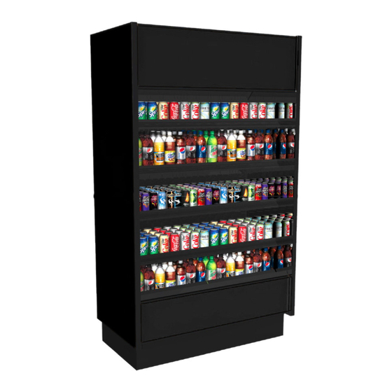
MODEL B424TM Shown
(With Optional Night Air Curtain)
Model B424TM..................................................... 47 1/4"L* x 25"D x 84 3/4"H~
Model B424TM.4489............................................. 47 1/4"L* x 25"D x 84 3/4"H~
Model B424TM.4857..............................................47 1/4"L* x 25"D x 84 3/4"H~
Model B824TM.....................................................92 1/4"L* x 25"D x 84 3/4"H~
*Includes End Panels
~ Units With Levelers Extended 1 5/8" Below Base Frame To Attain Listed Height
888 E. Porter Road · Muskegon, MI 49441 Phone: 231.798.8888 Fax: 231.798.4960 www.structuralconcepts.com
PN 54298
Rev E Date: 3.25.2015
Advertisement
Table of Contents
Troubleshooting

Subscribe to Our Youtube Channel
Related Manuals for Structural Concepts Oasis B824TM


Summary of Contents for Structural Concepts Oasis B824TM
- Page 1 READ AND SAVE THESE INSTRUCTIONS INSTALLATION AND PN 54298 OPERATING MANUAL IN AISLE SELF-SERVICE REFRIGERATED CASES WITH TOP MOUNT CONDENSER PACKAGE MODEL B824TM Shown (With Optional Upper Lights) MODEL B424TM Shown (With Optional Night Air Curtain) Model B424TM……………………………………...…..47 1/4”L* x 25”D x 84 3/4”H~ Model B424TM.4489……………...……………….……..
-
Page 2: Table Of Contents
TABLE OF CONTENTS OVERVIEW / NSF® TYPE / COMPLIANCE / WARNINGS / PRECAUTIONS ...………..…...………. INSTALLERS: FOLLOW THESE INSTRUCTIONS! ………….………………………………………..….. POSITIONING CASE / SHIMMING SUPPORT RAILS / ADJUSTING LEVELERS ………………..…... CASE STARTUP & REFRIGERATION PACKAGE ACCESS - MODELS B424TM, B424TM.4489 & B424TM.4857 ...…………………………………………………………………………………...…... -
Page 3: Overview / Nsf® Type / Compliance / Warnings / Precautions - Page 1 Of 2
80 °F (27 °C) and 60% maximum humidity. These Structural Concepts Oasis® self-service If unsure if your unit is Type I or II, see tag next to serial cases are designed to merchandise packaged label. -
Page 4: Overview / Nsf® Type / Compliance / Warnings / Precautions
OVERVIEW / NSF® TYPE / COMPLIANCE / WARNINGS / PRECAUTIONS - PAGE 2 of 2 PRECAUTIONS Following are important precautions to prevent damage to unit or merchandise. Please read carefully! See previous page for specifics on OVERVIEW, TYPE I AND TYP II ENVIRONMENTAL CONDITIONS, COMPLIANCE and WARNINGS. -
Page 5: Installers: Follow These Instructions
SCC P/N 54113 INSTALLERS: FOLLOW THESE INSRUCTIONS 1. Remove Shipping Brackets Attached to Skid Remove screws holding Case Shipping Brackets to skid. Remove Case Shipping Brackets from Skid. See illustration at right. Note: Shipping Brackets will vary in size, shape, material and location depending upon case type and model. -
Page 6: Positioning Case / Shimming Support Rails / Adjusting Levelers
POSITIONING CASE / SHIMMING SUPPORT RAILS / ADJUSTING LEVELERS Note: Units shown may not depict an exact representation of your particular unit being installed. 1. Position & Align Case Alongside Other Cases Before adjusting levelers (or shimming frame support rails), make certain that the case is in proper position and, if required, aligned with adjoining case(s). -
Page 7: B424Tm.4857
CASE STARTUP & REFRIGERATION PKG. ACCESS - MODELS B424TM, B424TM.4489 & B424TM.4857 Caution! To avoid injury, check temperature of Electrical and Control Access pan prior to handling condensate pan. Main power cord and switch are accessible from If condensate pan must be removed from unit the top front right hand side of header assembly. -
Page 8: Case Startup & Refrigeration Package Access - Model B824Tm Only
CASE STARTUP & REFRIGERATION PACKAGE ACCESS - MODEL B824TM ONLY Electrical and Control Access To avoid injury, check temperature of pans prior to accessing. Main power cord and switch are accessible from the See PREVENTIVE MAINTENANCE (TO BE top front right hand side of header assembly. -
Page 9: Case Startup & Refrigeration Assembly Access - Evap. Coil Fan / Txv Valve
CASE STARTUP & REFRIGERATION ASSEMBLY ACCESS - EVAP. COIL FAN / TXV VALVE 1. Evaporator Coil Fan Discharge When Main Power Switch is turned on, Refrigeration Assembly will energize (see CASE START-UP & REFRIGERATION ASSEMBLY ACCESS section). Evaporator Coil fan should turn on. From inside of the case, check for discharge air from honeycomb discharge duct (see next page for honeycomb location), to confirm that the fan is functioning properly. -
Page 10: Honeycomb Air Diffuser Access / Removal / Installation
HONEYCOMB AIR DIFFUSER ACCESS / REMOVAL / INSTALLATION 1. Honeycomb Air Diffuser Removal Honeycomb is located in discharge air duct. Use a device of suitable strength and agility such as a ballpoint pen or long nose pliers. Wedge instrument in Honeycomb near the Front Honeycomb Retainer Lip (see illustration below). -
Page 11: Light Fixtures (Including Optional Lights In Header)
LIGHT FIXTURES (INCLUDING OPTIONAL LIGHTS IN HEADER) Optional: Lights in Headers Are Accessible From Top of Case. Ample Space is Provided For Lamp Removal/Replacement Light Switch Light Fixtures (Note: Light Fixtures May Not Be on All Cases) Warning! Disconnect power before providing maintenance and service to unit. -
Page 12: Condensate Pump And Pan Access
CONDENSATE PUMP AND PAN ACCESS Condensate Pump Pan Access Warning! Disconnect power before providing maintenance and service to unit. Remove the two (2) screws holding the toe kick in place. (see illustration below). The Condensate Pan is accessible from the bottom of the unit. Unplug the Condensate Pan from its outlet. -
Page 13: Optional Night Air Curtain Operating Instructions
OPTIONAL NIGHT AIR CURTAIN OPERATING INSTRUCTIONS Optional Night Air Curtain Operating Instructions 1. Use caution when handling Night Air Curtain. 2. Display case may come with Night Curtain already attached. If not, a retrofit kit will be provided. If using SCC-supplied retrofit kit, attach to display case by inserting screws at top-underside of display case. -
Page 14: General Cleaning (To Be Performed By Store Personnel)
GENERAL CLEANING (TO BE PERFORMED BY STORE PERSONNEL) AREA TO CLEAN FREQ. INSTRUCTIONS Case Exterior Daily Acrylic (if Any): Clean with a warm water and mild soap solution and soft cloth. Never use ammonia-based cleaners on acrylic. Daily to Case Front/Sides/Bumper: Use a mild soap and water solution and a Weekly soft cloth. -
Page 15: Troubleshooting (To Be Performed By Store Personnel)
TROUBLESHOOTING (TO BE PERFORMED BY STORE PERSONNEL) CONDITION TROUBLESHOOTING Case Is Not Level See POSITIONING CASE / SHIMMING SUPPORT RAILS / ADJUSTING LEVELERS section in manual for additional information. Water Is On The Floor Call service provider. Fan Emits Excessive Noise Call service provider. -
Page 16: General Cleaning (To Be Performed By Trained Service Providers Only)
GENERAL CLEANING (TO BE PERFORMED BY TRAINED SERVICE PROVIDERS ONLY) WARNING! TURN OFF CASE BEFORE PERFORMING GENERAL CLEANING! AREA TO CLEAN FREQUENCY INSTRUCTIONS Case Interior Monthly Evaporator Fan Shroud Area (Under Decking): Caution! Due to rotating fans in area, turn off case and disconnect plug from wall outlet before beginning fan shroud (and surrounding tub area) cleaning! 1) Turn off power. -
Page 17: Preventive Maintenance
PREVENTIVE MAINTENANCE (TO BE PERFORMED BY TRAINED SERVICE PROVIDERS) WARNING! TURN OFF CASE BEFORE PERFORMING PREVENTIVE MAINTENANCE! PREVENTIVE FREQ. INSTRUCTIONS MAINTENANCE Case Exterior Quarterly Under Case Cleaning: Whenever accessing condensate pump pan at underside of case, vacuum (or use broom) under the case to remove all dust, debris and dirt that may collect. -
Page 18: Troubleshooting (To Be Performed By Trained Service Providers Only)
TROUBLESHOOTING (TO BE PERFORMED BY TRAINED SERVICE PROVIDERS ONLY) CONDITION TROUBLESHOOTING Water Is On The Floor Check that the drain trap is free of debris. Check that the drain hose is correctly positioned over evaporator pan. Check store conditions. For NSF®... -
Page 19: Troubleshooting (To Be Performed By Trained Service Providers Only)
TROUBLESHOOTING (TO BE PERFORMED BY TRAINED SERVICE PROVIDERS ONLY), CONTINUED CONDITION TROUBLESHOOTING Control Display Is See your case’s serial label for your model’s specified settings. See SERIAL Flashing LABEL LOCATION & INFORMATION LISTED / TECH INFO & SERVICE section in manual for label location, etc. Case Is Not Holding If a large amount of warm product was added to the case, it will take time for the Temperature... -
Page 20: Troubleshooting - Condensing System
TROUBLESHOOTING - CONDENSING SYSTEM (TRAINED SERVICE PROVIDERS ONLY) TROUBLESHOOTING - CONDENSING SYSTEM (BY TRAINED SERVICE PROVIDERS ONLY) CONDITION TROUBLESHOOTING Head Pressure Too High Check that the condensing coil is not dirty or covered. Check that condensing fans are working. Check that refrigerant is not overcharged. Perform sub-cooling check and verify that no contaminates are in system. -
Page 21: Troubleshooting - Evaporator System
TROUBLESHOOTING - EVAPORATOR SYSTEM (TRAINED SERVICE PROVIDERS ONLY) CONDITION TROUBLESHOOTING Low Suction Pressure Check if sight glass is flashing or showing low charge. Check that expansion valve (TXV) isn’t restricted. Check element charge. Check that liquid line or filter isn’t restricted. Check that refrigeration lines and/or hoses are not kinked on either high or low sides. -
Page 22: Serial Label Location & Information Listed / Tech Info & Service
For additional technical information and service, see the TECHNICAL SERVICE page in this manual for instructions on contacting Structural Concepts’ Technical Service Department. See images below for samples of both refrigerated and non-refrigerated serial labels. -
Page 23: Carel® Controller Operating Instruction
Read And Save These Instructions - Page 1 of 3 Integrated Electronic Microprocessor Controller Programming The Instrument ▲ mute To Modify The Setpoint ▼ Press and hold the “SET” key for at least 1 second. 2. Use arrow keys ▲ ▼ on temperature ▲... - Page 24 Read And Save These Instructions - Page 2 of 3 Integrated Electronic Microprocessor Controller User Interface - Display Summary Table of Alarm and Signals: Display, Buzzer and Relay reset alarms w/manual reset / reset HACCP alarms / reset temp. monitoring...
- Page 25 Read And Save These Instructions - Page 3 of 3 Integrated Electronic Microprocessor Controller Summary Table of Operating Parameters CODE PARAMETER UOM* TYPE MINIMUM MAXIMUM DEFAULT Select Celsius (°C) or Fahrenheit (°F) flag Calibration of probe 1 °C/°F Calibration of probe 2 °C/°F For Case Specific...
-
Page 26: Scc Technical Service Contact Information & Warranty Information
LIMITED WARRANTY All sales by Structural Concepts Corporation (SCC) are subject to the following limited warranty. “Goods” refers to the product or products being sold by SCC. Warranty Scope: Warranty is for equipment sold in the United States, Canada, Mexico and Puerto Rico. Equipment sold elsewhere may carry modified warranty.
Need help?
Do you have a question about the Oasis B824TM and is the answer not in the manual?
Questions and answers