Structural Concepts K Series Installation & Operating Manual
Angled base - full ends, straight base cutaway ends, modified base cutaway ends, straight base with full ends, storage
unit at rear, straight base - full ends, angled base - full ends, metal end panel with sink, rear sliding doors - plexi plenum, with pat
Table of Contents
Advertisement
SELF-SERVICE REFRIGERATED DISPLAY CASES (SELF-CONTAINED & REMOTE)
PLEASE NOTE THE FOLLOWING:
1.
YOUR SPECIFIC MODEL NUMBER IS ON THE SERIAL LABEL ON CASE REAR (NEAR MAIN POWER SWITCH).
2.
ILLUSTRATIONS SHOWN BELOW LIST "(L)" TO REFLECT VARYING CASE LENGTH DIMENSIONS.
3.
CASES SHOWN REFLECT FULL & OPEN END PANELS / STRAIGHT OR ANGLED BASES. YOURS MAY DIFFER.
4.
SEE "MODELS (AND THEIR RESPECTIVE CASE DIMENSIONS) LISTED IN THIS MANUAL" SECTION FOR
ADDITIONAL INFORMATION REGARDING SPECIFIC CASE DIMENSIONS OF STANDARD MODELS AND CDRs.
HV(L)56RSS
Angled Base - Full Ends
HV(L)39RSS (including Q3713)
Straight Base - Full Ends
HV7439RSS.3713A
Angled Base - Full Ends
HV(L)RSSRD
Straight Base - Full Ends
Rear Sliding Doors - Plexi Plenum
Oper Manuals\Standard\Self_Service_Refrig_Oper_Manual_54382.pub
READ AND SAVE THESE INSTRUCTIONS
HV(L)RSS
HV48RSS.3635A
Straight Base
Modified Base
Cutaway Ends
Cutaway Ends
HV42(L)RSS
Angled Base - Full Ends
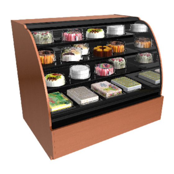
HVK(L)RSS
"K" Series
Straight Base - Full Ends
888 E. Porter Road · Muskegon, MI 49441 Phone: 231.798.8888 Fax: 231.798.4960 www.structuralconcepts.com
INSTALLATION &
OPERATING MANUAL
HV(L)48RSS
Straight Base
With Full Ends
HV(L)56RSS
Straight Base
Full Ends
RG2Z5080
PN 54382
HV3674RSS.5954 With
White Medex® Storage
Unit At Rear
HV36112RSS.4863A
Metal End Panel With Sink
HV36112RSS.4922B
With Patisserie in Top Section
(See Patisserie Section in Manual)
Rev R Date: 2.27.2015
Advertisement
Table of Contents
Troubleshooting

Subscribe to Our Youtube Channel
Related Manuals for Structural Concepts K Series


Summary of Contents for Structural Concepts K Series
- Page 1 READ AND SAVE THESE INSTRUCTIONS INSTALLATION & OPERATING MANUAL PN 54382 SELF-SERVICE REFRIGERATED DISPLAY CASES (SELF-CONTAINED & REMOTE) PLEASE NOTE THE FOLLOWING: YOUR SPECIFIC MODEL NUMBER IS ON THE SERIAL LABEL ON CASE REAR (NEAR MAIN POWER SWITCH). ILLUSTRATIONS SHOWN BELOW LIST “(L)” TO REFLECT VARYING CASE LENGTH DIMENSIONS. CASES SHOWN REFLECT FULL &...
-
Page 2: Table Of Contents
TABLE OF CONTENTS TABLE OF CONTENTS …………………………………………………………………………………..…..MODELS LISTED IN MANUAL (AND DETERMINING THEIR RESPECTIVE CASE DIMENSIONS) …. OVERVIEW / TYPE / COMPLIANCE / WARNINGS / PRECAUTIONS / WIRING ...……...…………..INSTALLATION: REMOVAL FROM SKID (LEVELERS AND RAILS vs. CASTERS) …………………..INSTALLATION: LOWER FRONT PANEL REMOVAL (ANGLED vs. -
Page 3: Models Listed In Manual (And Determining Their Respective Case Dimensions)
MODELS LISTED IN THIS MANUAL (AND DETERMINING THEIR RESPECTIVE CASE DIMENSIONS) DETERMINING YOUR MODEL AND ITS CASE DIMENSIONS: Note 1. Your model number can be found on serial label at rear of case (near main power switch). Note 2. Dimensions of most models can be found at www.structuralconcepts.com. Simply enter the case model number into the Product Number Search box. -
Page 4: Overview / Type / Compliance / Warnings / Precautions / Wiring
80 °F (27 °C) and 60% maximum humidity. These Structural Concepts self-service cases are If unsure if your unit is Type I or II, see tag next to serial designed to merchandise packaged products at label. - Page 5 OVERVIEW / TYPE / COMPLIANCE / WARNINGS / PRECAUTIONS / WIRING / PLUGS - PAGE 2 of 2 PRECAUTIONS WIRING DIAGRAM Following are important precautions to prevent Each case has its own wiring diagram folded and in its damage to unit or merchandise.
-
Page 6: Installation: Removal From Skid (Levelers And Rails Vs. Casters)
INSTALLATION: REMOVAL FROM SKID (LEVELERS AND RAILS vs. CASTERS) 1. Remove Case From Skid (Levelers and Rails) Remove shipping brace that may be securing case to skid. Support case to prevent tipping. Caution! Levelers can be damaged if case hits floor with heavy force! ... -
Page 7: Installation: Lower Front Panel Removal (Angled Vs. Vertical / Screw Vs. Slot)
INSTALLATION: LOWER FRONT PANEL REMOVAL (ANGLED vs. VERTICAL / SCREW vs. SLOT) 3A. Angled Lower Front Panels (Screws) Upper Panel Upper Panel Support: Support >> Remove screws located behind upper front panel. Lower Panel Support: >> For most applications, screws secure the lower panel support (located below front panel) to the unit. -
Page 8: Installation: Adjusting Front Panels / Adjoining Units / Glass Shelving
Grasp firmly and carefully install. Caution! Check that plastic edging is intact before placing glass shelving onto brackets! Plastic edging must not be removed from glass shelves. Contact Structural Concepts for Glass replacement edging (see TECHNICAL Shelves SERVICE CONTACT INFORMATION section). ... -
Page 9: Installation: Electrical Connections / Locking Casters / Adjusting Levelers
INSTALLATION: ELECTRICAL CONNECTIONS / LOCKING CASTERS / ADJUSTING LEVELERS 7. Electrical Connections Ballast A. Rear Wire-Ways Remove screws from rear wire-way cover to access electrical leads. Wiring runs case to case through base cut-outs. Wireway Raceway Knockout is provided in bottom of wire-way for Cover stub-out connection. -
Page 10: Installation: Refrigeration Lines / Stub-Outs / Drains / Wiring Diagrams / Ventilation
INSTALLATION: REFRIGERATION LINES / STUB-OUTS / DRAINS / WIRING DIAGRAMS / VENTILATION 10. Refrigeration Line Stub-out Connections Cutout (Remote Units) Remove front panel. Refrigerant stub-out access opening is usually at the front on the left hand side of the base (see illustration at top-right). -
Page 11: Installation: Display Case Start-Up (Front Access)
INSTALLATION: DISPLAY CASE START-UP (FRONT ACCESS) > Remote Cases Without Light Controls On 15. Display Case Start-Up (Front Access) Controller: A. Case Light are hard-wired to always come on when Case powers up when properly field-wired. case is energized. ... -
Page 12: Installation: Display Case Start-Up (Rear Access)
INSTALLATION: DISPLAY CASE START-UP (REAR ACCESS) 16. Display Case Start-Up (Rear Access) C. Temperature Controller (All Self-Contained Units and some Remote Units) A. Case Temperature controller varies depending upon Turn main power on at case rear. model. See TEMPERATURE CONTROLLER ... -
Page 13: Drain, Hose And Bracket Placement
NOTE: BELOW ILLUSTRATIONS MAY NOT EXACTLY REFLECT EVERY DRAIN, HOSE AND BRACKET PLACEMENT ILLUSTRATIONS PARTICULAR CASE’S FEATURES 2. Hot Gas Condensate System Three Condensate Systems Are Illustrated Below: Hot gas serpentine coil is routed through a condensate Illustration #1: Hot gas “CopeVap” condensate reservoir allowing water to be heated. -
Page 14: Night Air Curtain Operating Instructions (Optional)
OPTIONAL NIGHT AIR CURTAIN INST. & OPERATING (MODELS HV(L)RSS, HMO(L)36R, HMO(L)53R) Night Air Curtain Installation & Operating Instructions NOTE: THE 1. Use caution when handling Night Air Curtain. BELOW 2. Display case may come with Night Curtain already attached. If not, a retrofit kit will be ILLUSTRATION provided. - Page 15 OPTIONAL NIGHT AIR CURTAIN INST. & OPER. INSTRUCTIONS (MODEL HVK(L)RSS / HVK42(L)RSS) Night Air Curtain Installation & Operating Instructions NOTE: THE 1. Use caution when handling Night Air Curtain. BELOW 2. Display case may come with Night Curtain already attached. If not, a retrofit kit will be provided.
-
Page 16: Security Grid Information
SECURITY GRID INFORMATION - PAGE #1 of 2 Initial Positioning and Installation of Security Grid 1. Due to weight and size, Security Grid installment requires two (2) people. NOTE: 2. After hoisting the Security Grid directly over Front Air Deflector, drop the (2) ILLUSTRATIONS Security Grid Positioning Tabs into the Baffle Airflow Slots (see enlarged view MAY NOT... - Page 17 SECURITY GRID INFORMATION - PAGE #2 of 2 Securing Security Grid Into Place and Locking 1. After leaning the Security Grid back against the two Security NOTE: Brackets, slide the (two) Padlocks through the Security Grid and the Security Brackets. ILLUSTRATIONS 2.
-
Page 18: Maintenance Fundamentals - Standard Light Fixtures
MAINTENANCE FUNDAMENTALS - FLUORESCENT LIGHTS 1. Fluorescent Light Fixture Warnings, Honeycomb Precautions and Warranty: Warning! Disconnect power before providing maintenance and service to unit. Fluorescent Caution: Lamps have been treated to resist Light breakage and must be replaced with similarly Fixtures treated lamps. -
Page 19: Maintenance Fundamentals - Led Lights/Brackets/Shelves/Drain/Txv Valve
1. LED Light Removal / Replacement: Bracket Retainer (Typical) LED lights they rarely require change-out. Contact Structural Concepts’ Technical Service Department for replacement parts (see Technical Service section of this guide). To remove LED light fixture, disconnect existing LED light from its brackets &... -
Page 20: Controller, Condensate Pan
If service is required to the temperature control unit, 5. Condensate Pan Access / Removal call Structural Concepts Corporation. Maintenance should be performed by a certified technician. Turn off main power; allow condensate pan to cool. -
Page 21: Maintenance Fundamentals - Hot Gas Loop Condens. Units (Hv48Rss.5536, Etc.)
MAINTENANCE FUNDAMENTALS - HOT GAS LOOP CONDENSATE UNITS (HV48RSS.5536, Etc.) This system also incorporates an overflow Hot Gas Loop Condensate Units (Model reservoir with heating element to ensure complete HV48RSS.5536, etc.) condensate removal. System Operation Hot gas loop condensate systems utilize a hot Indicator Light ... -
Page 22: Maintenance Fundamentals - Hot Gas Loop Condens. Units (Hv3674Rss.5954, Etc.)
MAINTENANCE FUNDAMENTALS - HOT GAS LOOP CONDENSATE UNITS (HV3674RSS.5954, Etc.) This system also incorporates an overflow Hot Gas Loop Condensate Units (Model reservoir with heating element to ensure complete HV3674RSS.5954, etc.) condensate removal. System Operation Hot gas loop condensate systems utilize a hot Indicator Light ... -
Page 23: Maintenance Fundamentals - Rear Doors / Rear Plenum / Magnetic Air Filter
MAINTENANCE FUNDAMENTALS - REAR DOORS / REAR PLENUM / MAGNETIC AIR FILTER Rear Sliding Doors the case; pivot the bottom of the door out. The metal door brackets are not connected to the Each rear sliding door has a perforated perforated Plexiglas plenum;... -
Page 24: Maintenance Fundamentals - Medex® Storage Unit/Supply Organizer Drawers
MAINTENANCE FUNDAMENTALS - MEDEX® STORAGE UNIT/SUPPLY ORGANIZER DRAWERS, ETC. Medex® Storage Unit (Found on Model HV3674RSS.5954, etc.) Consists of The Following: Two (2) pull-out drawers which are strong enough to support icing buckets Two (2) pull-out supplies organizer drawers ... -
Page 25: Maintenance Fundamentals - Patisserie Area (Model Hv36112Rss.4922B Only)
MAINTENANCE OF PATISSERIE AREA (MODEL HV36112RSS.4922B ONLY) Start-Up, Evaporator Fan Access/Removal, Expansion Valve/Condensate Drain Access Note: Photos and illustrations shown may not reflect every feature or option of your particular case. Illustration #1: Disconnect power from Case. Leads are provided at Right Rear, behind Rear Panel. ... - Page 26 MAINTENANCE OF PATISSERIE AREA (MODEL HV36112RSS.4922B ONLY), CONTINUED Start-Up, Evaporator Fan Access/Removal, Expansion Valve/Condensate Drain Access Photo #5: Sub-Deck being pulled up (and eventually out) to reveal Fan, Fan Housing & Shroud, etc. Illustration #6: View of Fan Housing, Fan Shroud, Fans, Drain, TXV Valves, etc. This is after the four Solid Surface Decks as well as the insulated Sub-Decks have been removed.
-
Page 27: General Cleaning (To Be Performed By Store Personnel)
GENERAL CLEANING (TO BE PERFORMED BY STORE PERSONNEL) AREA FREQ. INSTRUCTIONS Case Daily Acrylic: Clean acrylic sneeze guard with a mild soap and water solution and a soft Exterior cloth. Caution! Never use ammonia-based cleaners on acrylic. Incorrect cleaning agents or abrasive cleaning cloths cause surface to ‘cloud’ over time. Daily Glass / Mirrors (Including Sliding Door Glass): Clean side glass, glass shelves, and mirrors with a household or commercial glass cleaner. -
Page 28: Troubleshooting (To Be Performed By Store Personnel)
TROUBLESHOOTING (TO BE PERFORMED BY STORE PERSONNEL) CONDITION TROUBLESHOOTING Case Not Lining Up See Installation Section for instructions on properly aligning case (alongside other cases) and adjusting levelers (or rails). Water Is On The Floor Call service provider. Fan Emits Excessive Call service provider. -
Page 29: General Cleaning (To Be Performed By Trained Service Providers Only)
GENERAL CLEANING (TO BE PERFORMED BY TRAINED SERVICE PROVIDERS ONLY) AREA TO CLEAN FREQUENCY INSTRUCTIONS Case Interior Monthly Evaporator Fan Shroud Area (Under Decking): Caution! Due to rotating fans in area, turn off case and disconnect plug from wall outlet before beginning fan shroud (and surrounding tub area) cleaning! 1) Turn off power. -
Page 30: Troubleshooting (To Be Performed By Trained Service Providers Only) - Page 1 Of 3
TROUBLESHOOTING (TO BE PERFORMED BY TRAINED SERVICE PROVIDERS ONLY) - PAGE 1 of 3 CONDITION TROUBLESHOOTING Case Not Lining See Installation Section for instructions on properly aligning case (alongside other cases) and adjusting levelers. Water Is On The Caution! Water on flooring can cause much damage! Until cause is determined (and Floor repaired), following these procedures: ... -
Page 31: Troubleshooting (To Be Performed By Trained Service Providers Only) - Page 2 Of 3
TROUBLESHOOTING (TO BE PERFORMED BY TRAINED SERVICE PROVIDERS ONLY) - PAGE 2 of 3 CONDITION TROUBLESHOOTING Fan Emits Excessive Check that the case is aligned, level and plumb. Noise Check evaporator fan for cleanliness. Unplug/power off fan motors. Check motor shaft for bearing wear. Check that fan motors are securely mounted in brackets. -
Page 32: Troubleshooting (To Be Performed By Trained Service Providers Only) - Page 3 Of 3
TROUBLESHOOTING (TO BE PERFORMED BY TRAINED SERVICE PROVIDERS ONLY) - PAGE 3 of 3 CONDITION TROUBLESHOOTING Case Lights Are Not Check that Light switch is in the on position. Working Check that ALL of the light cords and plugs are properly connected. See MAINTENANCE - LIGHT FIXTURES (LED LIGHT FIXTURES) section. -
Page 33: Condensing System
TROUBLESHOOTING - CONDENSING SYSTEM (BY TRAINED SERVICE PROVIDERS ONLY) CONDITION TROUBLESHOOTING Head Pressure Too High Check that the condensing coil is not dirty or covered. Check that condensing fans are working. Check that refrigerant is not overcharged. Perform sub-cooling check and verify that no contaminates are in system. Check that liquid line filter dryer is not plugged. -
Page 34: Evaporator System
TROUBLESHOOTING - EVAPORATOR SYSTEM (BY TRAINED SERVICE PROVIDERS ONLY) CONDITION TROUBLESHOOTING Low Suction Pressure Check if sight glass is flashing or showing low charge. Check that expansion valve (TXV) isn’t restricted. Check element charge. Check that liquid line or filter isn’t restricted. Check that refrigeration lines and/or hoses are not kinked on either high or low sides. -
Page 35: Preventive Maintenance (To Be Performed By Trained Service Provider)
PREVENTIVE MAINTENANCE (TO BE PERFORMED BY TRAINED SERVICE PROVIDER) WARNING! TURN OFF CASE BEFORE PERFORMING PREVENTIVE MAINTENANCE! PREVENTIVE FREQ. INSTRUCTIONS MAINTENANCE Case Exterior Quarterly Condensing Coil: Remove panel to access area by lifting up and off or by screw removal (depending on case). -
Page 36: Maintenance Fundamentals - Honeycomb Air Diffusers
MAINTENANCE FUNDAMENTALS - HONEYCOMB AIR DIFFUSERS (SERVICE TECHNICIANS ONLY) Honeycomb Air Diffuser Removal Clean honeycomb with warm water and soap solution. Submerse if necessary. Use brush to See PREVENTIVE MAINTENANCE (TO BE dislodge stubborn or sticky residue. Dry by using PERFORMED BY TRAINED SERVICE PROVIDER) vacuum’s blow mode (vs. -
Page 37: Serial Label Information & Location
For additional technical information and service, see the TECHNICAL SERVICE page in this For additional technical information and service, see the TECHNICAL SERVICE page in this manual for instructions on contacting Structural Concepts’ Technical Service Department. manual for instructions on contacting Structural Concepts’ Technical Service Department. -
Page 38: Temperature Controller - Carel
Read And Save These Instructions - Page 1 of 3 Integrated Electronic Microprocessor Controller Programming The Instrument ▲ mute To Modify The Setpoint ▼ Press and hold the “SET” key for at least 1 second. 2. Use arrow keys ▲ ▼ on temperature ▲... - Page 39 Read And Save These Instructions - Page 2 of 3 Integrated Electronic Microprocessor Controller User Interface - Display Summary Table of Alarm and Signals: Display, Buzzer and Relay reset alarms w/manual reset / reset HACCP alarms / reset temp. monitoring...
- Page 40 Read And Save These Instructions - Page 3 of 3 Integrated Electronic Microprocessor Controller Summary Table of Operating Parameters CODE PARAMETER UOM* TYPE MINIMUM MAXIMUM DEFAULT Select Celsius (°C) or Fahrenheit (°F) flag Calibration of probe 1 °C/°F Calibration of probe 2 °C/°F For Case Specific...
-
Page 41: Temperature Controller - Dixell® Xm670K And Xm679K
NOTE: THIS PAGE MAY NOT LIST EVERY SETTING DIXELL® XM67(X)K CONTROLLER - PAGE 1 of 3 OR PARAMETER ON YOUR CONTROLLER Note: Units With These Temperature Controllers Have Been Hot-Keyed At Factory For General Operation. - Page 42 NOTE: THIS PAGE MAY NOT LIST EVERY SETTING DIXELL® XM67(X)K CONTROLLER - PAGE 2 of 3 OR PARAMETER ON YOUR CONTROLLER Note: Units With These Temperature Controllers Have Been Hot-Keyed At Factory For General Operation.
- Page 43 NOTE: THIS PAGE MAY NOT LIST EVERY SETTING DIXELL® XM67(X)K CONTROLLER - PAGE 3 of 3 OR PARAMETER ON YOUR CONTROLLER Note: Units With These Temperature Controllers Have Been Hot-Keyed At Factory For General Operation.
-
Page 44: Technical Service Contact Information & Warranty Information
LIMITED WARRANTY All sales by Structural Concepts Corporation (SCC) are subject to the following limited warranty. “Goods” refers to the product or products being sold by SCC. Warranty Scope: Warranty is for equipment sold in the United States, Canada, Mexico and Puerto Rico. Equipment sold elsewhere may carry modified warranty.
Need help?
Do you have a question about the K Series and is the answer not in the manual?
Questions and answers