
Subscribe to Our Youtube Channel
Related Manuals for Landoll Brillion SS16


Summary of Contents for Landoll Brillion SS16
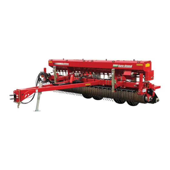
- Page 1 ‘ Sure Stand AG Seeder Models SS16 and SSP16 Operator’s Manual LANDOLL COMPANY, LLC 1900 North Street Marysville, Kansas 66508 (785) 562-5381 800-428-5655 ~ WWW.LANDOLL.COM F-1021-0422...
- Page 2 Manuals for Sure Stand AG Seeder Manual Number Manual Type F-1021 Operator’s Manual F-1020 Parts Manual...
- Page 3 DANGER DO NOT operate or perform any maintenance tasks on this equipment until you have completed the following: 1. Receive proper training to operate this equipment safely. 2. Read and understand the operator’s manual. 3. Be thoroughly trained on inspection and repair procedures. Failure to comply with this warning may result in serious injury or possibly death.
- Page 5 Table of Contents Safety Information Introduction ........... . 1-1 Description of Unit .
- Page 6 TABLE OF CONTENTS Console w/Clutch Control Electrical Layout - Optional ....2-28 Console w/Clutch Control Electrical Layout - Optional....2-29 Console w/Clutch Control - Seed Box Seed Shaft Assembly.
- Page 7 TABLE OF CONTENTS Settings Menu - Clutch Setting ........4-4 Settings Menu - Install Setup .
- Page 8 TABLE OF CONTENTS F-1021-0422...
- Page 9 Failure to comply with this warning can result in warranty obligation unless each product is registered personal injury or death, damage to the within 10 days of retail purchase, using the Landoll implement or its components and inferior Company, LLC Ag Products on-line registration process.
- Page 10 TABLE OF CONTENTS Safety • When applying decals to the implement, be sure to clean the surface to remove any dirt or residue. Where possible, sign placement should protect the sign from NOTE abrasion, damage, or obstruction from mud, dirt, oil etc. Investigation has shown that nearly 1/3 of all farm DANGER accidents are caused by careless use of machinery.
- Page 11 TABLE OF CONTENTS Transporting Safety Attaching, Detaching and Storage IMPORTANT • Do not stand between the tractor and implement It is the responsibility of the owner/operator to when attaching or detaching implement unless both comply with all state and local laws. are not moving.
- Page 12 TABLE OF CONTENTS Tire Safety Safety Chain Tire changing can be dangerous and should be 1. Use a safety chain to help control drawn machinery performed by trained personnel using correct tools and should it separate from the tractor drawbar. equipment.
- Page 13 TABLE OF CONTENTS Decals WARNING CLOSED A LANDOLL PRODUCT ITEM 1 170509 OPEN MOVING PART HAZARD TO PREVENT SERIOUS INJURY FROM MOVING PARTS: ITEM 3 ITEM 2 KEEP COVERS CLOSED DURING OPERATION. DO NOT ALLOW ANYONE TO RIDE OR CLIMB...
- Page 14 TABLE OF CONTENTS Figure 1-5: Decal Locations, SS16 Front and Back Views (1 of 2) F-1021-0422...
- Page 15 TABLE OF CONTENTS Figure 1-6: Decal Locations, SS16 Side Views (2 of 2) F-1021-0422...
- Page 16 TABLE OF CONTENTS Figure 1-7: Decal Locations, SSP16 Front and Back (1 of 2) F-1021-0422...
- Page 17 TABLE OF CONTENTS RIGHT SIDE VIEW LEFT SIDE VIEW Figure 1-8: Decal Locations, SSP16 Side Views (2 of 2) F-1021-0422...
- Page 18 TABLE OF CONTENTS Table provided for general use. NOTES: 1-10 F-1021-0422...
- Page 19 Chapter 2 TABLE OF CONTENTS Assembly IMPORTANT CAUTION All harnesses must be firmly attached to machine frame members, or nylon tubing, so they don’t sag or Do not work on or under this machine unless become torn loose by field debris. Use the tie straps securely blocked and supported by a hoist or provided.
- Page 20 TABLE OF CONTENTS Drawbar Installation 2. Install Toolbox to Drawbar cross member with 3/8-16 x 1 Bolts, Flat Washers and Flanged Locknuts. 3. Attach Air Manifold Assembly to the Drawbar cross WARNING member with 5/8-11 x 1-3/4 Bolt, Flat Washer and Flanged Locknut.
-
Page 21: Bolt
TABLE OF CONTENTS Wheel Arm Installation 4. Install 3 x 8 Hydraulic Cylinder to the Wheel Arm Bracket, by sliding a 1 x 2 11ga SS Washer over 1 x 1. Position Wheel Arm Assembly into the Wheel Arm 8-3/4 Pin and insert into Wheel Arm Bracket and Bracket. - Page 22 TABLE OF CONTENTS 3-PT Hitch Installation 3. Attach the Toolbox to the 3-PT Hitch with 3/8-16 x 1 Bolts, Flat Washers and Flanged Locknuts. 1. Center the 3-PT Hitch Assembly to Seeder Frame 4. Insert Top Link and lower 3-PT Pins. Secure with 7/16 and attach with 3/4-10 U-Bolts, Flat Washers and Lynch Pins.
- Page 23 TABLE OF CONTENTS 5. Attach the Manual Holder to the 3-PT Hitch with 7. Place the Calibration Crank and Wrenches in the 1/4-20 x 1 Bolts, Flat Washers and Locknuts. Toolbox. See Figure 2-4. 6. Attach the Connector Holder to the Air Manifold Bracket Assembly with 1/4-20 x 3/4 Bolts, Flat Washers and Locknuts.
- Page 24 TABLE OF CONTENTS Drawbar Air System 4. Cut off any excess Nylon Tubing and insert ends into the Air Manifold Assembly Push to Connect Elbows. Installation Cut ends of Nylon Tubing should be smooth and burr free. Burrs can cause slow leaks. 1.
- Page 25 TABLE OF CONTENTS 3-PT Hitch Air System 4. Cut off any excess Nylon Tubing and insert ends into the Air Manifold Assembly Push to Connect Elbows. Installation Cut ends of Nylon Tubing should be smooth and burr free. Burrs can cause slow leaks. 1.
- Page 26 TABLE OF CONTENTS Hydraulic Installation Tightening Procedure for JIC 37 degree Swivel Female Nuts. 1. Check Fitting Flare and seat for defects. WARNING 2. Lubricate the connection. Escaping hydraulic fluid can cause serious 3. Install Hydraulic Hoses without twists. personnel injury. Relieve system pressure before 4.
- Page 27 TABLE OF CONTENTS 2. Install Elbow Fitting into rod end of each 3 x 8 6. Route the hoses along frame to Bulkhead Bracket Hydraulic Cylinder. See Figure 2-9. and attach to Bulkhead Tees. 3. Install Bulkhead Tees into SMV Bracket using 7.
- Page 28 TABLE OF CONTENTS Drawbar Model Warning IMPORTANT Lamps Installation All harnesses must be firmly attached to machine frame members, or nylon tubing, so they don’t sag or Amber Lamps are assembled to the outer extremity of become torn loose by field debris. Use the tie wraps machine.
- Page 29 TABLE OF CONTENTS Figure 2-10: Drawbar Warning Lamps Installation F-1021-0422 2-11...
- Page 30 TABLE OF CONTENTS 3-PT Hitch Model Warning IMPORTANT Lamps Installatio All harnesses must be firmly attached to machine frame members, or nylon tubing, so they don’t sag or Amber Lamps are assembled to the outer extremity of become torn loose by field debris. Use the tie wraps machine.
- Page 31 TABLE OF CONTENTS Figure 2-11: 3-PT Hitch Warning Lamps Installation F-1021-0422 2-13...
- Page 32 TABLE OF CONTENTS Clutch Installation - Optional Assembly instruction for models without a factory installed Clutch. 1. On the outside of the Clutch Transmission Side Plate top 2-3/16" hole, install Flangettes and Bearing with 5/16-18 x 1 Carriage Bolts, Lock Washers and Nuts. See Figure 2-12.
- Page 33 TABLE OF CONTENTS Locknut,1/4-20 Flat Washer,1/4 Hose Clamp Key,Sq 3/16 x 1 Grommet Speed Reducer Flangette Half Carriage Bolt, 5/16-18 x 1 Carriage Bolt, Spacer, 5/16-18 x 1-1/4 1/4 x 3/8 x 3/8 Bearing Bolt,1/4-20 x 1 Double Chain Magnet Wheel Coupler Chain Idler...
- Page 34 TABLE OF CONTENTS Basic Clutch Switch Box Assembly - Optional Switch Box Assembly instruction for models with an installed Clutch. 1. Connect Clutch Cable Assembly to the Clutch Connector and route along Frame and Drawbar/3-PT Toggle Hitch. Secure to Frame and Drawbar/3-PT Hitch or Switch with Hydraulic Hoses and Warning Lamp Harness with tie wraps.
- Page 35 TABLE OF CONTENTS Table provided for general use. NOTES: F-1021-0422 2-17...
- Page 36 TABLE OF CONTENTS Brillion Elite Mini Monitor - See Figure 2-15. Inside the Seed Box, add enough slack to the Bin Level Sensor Cord to allow for future Optional adjustments of the Sensor. Secure the Bin Level Cord by tightening the Cord Grip Compression Nut. Connect Assembly instruction for models with Clutch.
- Page 37 TABLE OF CONTENTS Brillion Elite Mini Monitor - can also be raised or lowered to the desired seed level. Install Cord Grips from the inside of the Seed Box Field Installation - Optional out and secure with supplied Locknut on the outside of the Seed Box.
- Page 38 TABLE OF CONTENTS Brillion Elite Mini Monitor Electrical Layout Figure 2-17: Brillion Elite Mini Monitor Harness Layout 2-20 F-1021-0422...
- Page 39 TABLE OF CONTENTS Brillion Elite Mini Monitor - Single Seed Box Electrical Schematic Figure 2-18: Brillion Elite Mini Monitor - Single Seed Box Electrical Schematic F-1021-0422 2-21...
- Page 40 TABLE OF CONTENTS Brillion Elite Mini Monitor - Seed Box Seed Shaft Sensor Screw,Rnd Hd Flat Washer,1/4 1/4-20 x 1 Flat Washer, Spacer w/Magnet Lock Washer,1/4 Nut,1/4-20 Locknut, Seed Shaft, Flange #8-32 3/8 Square Screw,Rnd Hd Sensor Mount #8-32 x 1-1/4 Smart Washer,Flat #8 Shaft Sensor...
- Page 41 TABLE OF CONTENTS Brillion Elite Mini Monitor - Bin Level Sensor Flange Locknut,#8-32 Cord Grip Compression Nut Bin Level Sensor Cord Grip Bin Level Includes Locknut Sensor Bracket Flat Washer,3/8 Flange Locknut,3/8-16 3-Pin Shroud Bolt,3/8-16 x 1-1/4 Cord Grip Compression Nut Bin Level Sensor Flange Locknut, #8-32...
- Page 42 TABLE OF CONTENTS Brillion Elite Mini Monitor - Ground Speed Sensor Clutch Connector Bolt,Carriage 5/16-18 x 1 Actuator Assembly Includes Set-Screw Washer,Flat #8 Screw,Rnd Hd Set Screw #8-32 x 1-1/4 Locknut,Flange #8-32 Clutch Shaft Smart Shaft Bracket, Sensor Pickup Switch Clutch Connector Actuator Assembly...
- Page 43 TABLE OF CONTENTS Brillion Elite Mini Monitor 4. Attach the Monitor Mount to the Straight Bracket with #10-24 x 1 Machine Screws, Flat Washers, Lock Tractor Installation - Optional Washers, and Nuts, provided with Monitor Mount. 5. With the Brillion Elite Mini Tractor Harness, plug the 1.
- Page 44 TABLE OF CONTENTS Acre Meter Installation - Optional Acre Meter Angle Ground Used with No Clutch, Basic Clutch or Console Wire w/Clutch Control The acre meter consists of three main parts: the Acre Meter, the Pick-up Switch and the Magnet Wheel Assembly.
- Page 45 TABLE OF CONTENTS Bolt, Acre 5/16-18 x 1 Meter Angle Flat Washer,#8 Lock Washer,#8 Lock Washer,5/16 Nut,#8-32 Nut,#6-32 Ground Wire Nut,5/16-18 Lock Washer,#8 Screw, Nut,3/8-16 #8-32 x 1-1/2 Magnet Wheel Assembly Lock Washer,3/8 Pick-Up Switch Screw, #6-32 x 1/2 Flat Washer,3/8 Acre Meter Assembly Bolt,3/8-16 x 1-1/4...
- Page 46 TABLE OF CONTENTS Console w/Clutch Control 2. Connect either 4 ft (3-PT) or 20 ft (Drawbar) Extension Harness to the Clutch Harness. Route Electrical Layout - Optional along 3-PT Hitch or Drawbar towards front of machine. See Figure 2-25. The clutch is controlled by a toggle switch on the 3.
- Page 47 TABLE OF CONTENTS Console w/Clutch Control Electrical Layout - Optional Figure 2-26: Clutch and Seed Shaft Sensor Layout - Optional F-1021-0422 2-29...
- Page 48 TABLE OF CONTENTS Console w/Clutch Control - 2. Install Sensor Bracket using Seed Meter existing 1/4-20 x 1 Machine Screws, Lock Washers and Nuts. Seed Box Seed Shaft 3. Install Seed Shaft Sensor onto Sensor Bracket. Assembly 4. After installation, seed meters need to be zeroed. See “Seed Rate Chart”...
- Page 49 TABLE OF CONTENTS Console w/Clutch Control 4. Plug Console 3-Pin Power Cord into the Tractor Convenience Outlet and 9-Pin Cord into the 4ft or 20ft Tractor Installation - Optional Extension Harness. 5. Check clutch operation: Clutch will engage when 1. Mount Angle Bracket onto Tractor where convenient power is applied.
- Page 50 TABLE OF CONTENTS Scale Installation - Optional 6. Carefully lower the Seed Box ensuring the cutout on the Seed Box goes over the Load Cell Cord. 7. Secure Seed Box to each Load Cell with two 3/4-10 x CAUTION 2 Bolts and Lock Washers. Do not work on or under this machine unless securely blocked and supported by a hoist or Bolt,3/4-10 x 2...
- Page 51 TABLE OF CONTENTS Scale Indicator Tractor 5. Tilt the GT400 Scale Indicator to latch the top of the GT400 Indicator Bracket. Secure bottom with 1/4-20 Installation - Optional x 1/2 Bolts and Spiral Flanged Locknuts. 6. Plug the Power and Indicator Cables into the bottom 1.
- Page 52 TABLE OF CONTENTS Coil Tine Harrow Installation - Optional CAUTION Do not work on or under this machine unless securely blocked and supported by a hoist or tractor or by other sufficient means. 1. Attach the two Harrow Mounting Brackets to the Frame Tube with 3/4-10 U-Bolts, Flat Washers and Locknuts.
- Page 53 TABLE OF CONTENTS Harrow Assembly U-Bolt,3/4-10 Flat Washer,3/4 Locknut,3/4-10 Jack,Sidewind Bolt,5/8-11 x 1-3/4 Harrow Mounting Bracket Bolt, 1/2-13 x 3-3/4 Locknut,5/8-11 Hitch Pin,3/4 x 4-1/2 Hair Pin Cotter Locknut,5/8-11 Washer,0.656 x 2.063 x 0.375 Harrow Adjuster U-Bolt,5/8-11 Flanged Locknut,1/2-13 Figure 2-32: Coil Tine Harrow F-1021-0422 2-35...
- Page 54 TABLE OF CONTENTS S-Tine Harrow Installation - Optional CAUTION Do not work on or under this machine unless securely blocked and supported by a hoist or tractor or by other sufficient means. 1. Attach the Harrow Mounting Brackets to the Seeder Frame Tube with 3/4-10 U-Bolts, Flat Washers, and Locknuts.
- Page 55 TABLE OF CONTENTS Square Tube U-Bolt,3/4-10 x 7-13/16 x 9-1/4 Harrow Mounting Bracket Flat Washer,3/4 Locknut,3/4-10 Jack Reversible Bolt,5/8-11 x 1-3/4 Point Bolt,7/16 x 3-1/2 Clamp Locknut,7/16-14 S-Tine Bolt,1/2-13UNC x 3-3/4 Locknut,5/8-11 Hitch Pin Flange Bolt,3/8-16 Locknut,3/8-16 x 1-3/4 Hair Pin Duckfoot Point Locknut,5/8-11 Washers,0.656 x 1.063 x 0.375...
- Page 56 TABLE OF CONTENTS S-Tine Hydraulic Harrow 6. Install a 45 degree Elbow Fitting on the base port of each Harrow Arm 2 X 3 Cylinder. Installation – Optional 7. Attach 1/4 x 80 Hoses to the Harrow Arm 2 x 3 Cylinders.
- Page 57 TABLE OF CONTENTS Bulkhead Hose Asm, Hose Asm, 3/8 x 214 1/4 x 80 Hose Asm, 1/4 x 80 EXISTING HARDWARE Bulkhead SMV Bracket Hose Asm, 1/4 x 80 Hose Asm, U-Bolt, 1/4 x 80 3/4-10 x 9-1/4 Hose Asm, 3/8 x 214 Tube Sq 2 x 165...
- Page 58 TABLE OF CONTENTS Purge S-Tine Hydraulic Harrow System The S-Tine Hydraulic Harrow should be purged of air before operation. WARNING Escaping hydraulic fluid can cause serious personnel injury. Relieve system pressure before repairing, adjusting, or disconnecting. Wear proper hand and eye protection when searching for leaks.
- Page 59 Chapter 3 TABLE OF CONTENTS Operation DANGER DANGER DANGER DANGER Never allow anyone to ride on the Seeder at any Always lock the Tractor Drawbar in the center time. Allowing a person to ride on the machine position when transporting the unit. Failure to do can inflict serious personal injury or death to that so can result in serious injury or death and cause person.
- Page 60 TABLE OF CONTENTS Tractor Preparation 8. Connect the 7-Pin Connector to Tractor Outlet, routing cable by avoiding pinch points. The Sure Stand Seeder is available as a Pull-Type Hitch • Make sure the tractor has a good clean or 3-PT Hitch version. receptacle, free of dirt and corrosion.
- Page 61 TABLE OF CONTENTS Pin Ø1" Upper Pin Pin Ø1-1/8" 24" Lower Pin Category 2 Free Link Pin Ø1-1/4" Upper Pin Pin Ø1-7/16" 24" Lower Pin Category 3 Free Link Pin Ø1-1/4" Upper Pin Pin Ø1-7/16" 15" Lower Pin Category 2 Quick Hitch Pin Ø1-1/4"...
- Page 62 TABLE OF CONTENTS Attaching/Detaching 3-PT Hitch Seeder 3/4" Parking Pin WARNING To prevent the implement from tipping forward on Frame the frame, disengage parking stand only when the seeder is fully attached to the tractor. Be sure to observe the following sequences. Arm Guide Hooking Up the Seeder: 1.
- Page 63 TABLE OF CONTENTS Tractor Preparation/Attaching of Hyd Cyl Pull Type Seeder DANGER DANGER Hair Pin Cotter Do not allow any bystanders to stand between the tractor and the implement while backing up to the implement. 1. The Seeder is designed to be used with a Category 2 or 3 Drawbar Hitch.
- Page 64 TABLE OF CONTENTS Attaching/Detaching Pull Type Seeder Hyd Cyl Attaching the Seeder for Field Operations: Seeder is parked lowered 1. Attach Seeder to the Tractor. 2. Raise the Seeder fully to extend the Hydraulic Lift Cylinders and rotate the Transport Locks in the engaged position over the Cylinder Rod.
- Page 65 TABLE OF CONTENTS 1. Carefully hitch the Seeder to the tractor and connect the Hydraulic Lift Hoses. Pressure Gauge Air Manifold 2. Check to make sure the tractor hydraulic reservoir is Bracket full of the manufacturer’s recommended oil. 3. If the Transport Locks are engaged, raise the Seeder and remove the Transport Locks.
- Page 66 TABLE OF CONTENTS Seed Rate Adjustment IMPORTANT The Clutch if equipped must be disengaged (power WARNING off) when Seed Shafts are turned manually for Calibration. • To prevent damage to the seed meters, Do not If Seeder is not equipped with a Clutch, remove Chain apply excessive force to the adjusting nuts.
- Page 67 TABLE OF CONTENTS Seed Rate Chart PLANTING RATES FOR SS16/SSP16 (MICROMETER) IN POUNDS PER ACRE RATES ARE INTENDED AS A GUIDE ONLY. VARIATIONS IN SIZE AND CLEANLINESS WILL AFFECT RATES. CHECK ACREAGE AND POUNDS OF SEED USED FOR BEST RESULTS. * WILL CRACK SOME SEEDS AT THESE SETTINGS NOT RECOMMENDED: LENTILS, SORGHUM, SUDAN GRASS Figure 3-11: Seed Rate Chart...
- Page 68 Figure 3-13: Calibration Chain Figure 3-12: No Clutch Disengagement Landoll assumes no liability pertaining to Seeding Rates achieved with this Seeder. Rates listed are general in nature and should be used as starting points only. Seed varieties and blends listed represent those calibrated through in-house test meters.
- Page 69 TABLE OF CONTENTS Clutch Operation - Optional Brillion Elite Mini Monitor: Touch Screen Monitor provides the user the ability to toggle the Seeder Clutch "On" or "Off". Basic Clutch Switch: Toggle Switch on Switch Box, turns the Seeder Clutch "On" or "Off". Console w/Clutch Control: Toggle Switch on Switch Box, turns the Seeder Clutch "On"...
- Page 70 TABLE OF CONTENTS Brillion Elite Mini Monitor • Brillion Elite Mini Monitor is operated on a 12-Volt DC negative ground system. The monitor should be Brillion Elite Mini Monitor provides information to the connected using the existing convenience plug operator and acts as an interface for clutch control. The connection.
- Page 71 TABLE OF CONTENTS Electronic Acre Meter Kit - 1. If you know the number, select it using the UP and DOWN buttons. When you press the /FUNC button, Optional the Acre Counter will accept the number in the display as the new pulses per 400 feet. See Table 3-15.. Used with No Clutch, Basic Clutch or Console 2.
- Page 72 TABLE OF CONTENTS Changing the Password Select a new password using the UP and DOWN buttons. Press the /FUNC button until the word “SEt” appears in the display. Release the /FUNC button. The number in the display is your new pass code. Make sure you record this number.
- Page 73 TABLE OF CONTENTS Pulses Width MODEL per 400 Ft SSPT604 SSP4 SSP5 SSP6 SSP8 SSBP8 SSB8 SSP10 SSBP10 SS10 SSB10 10.0 SSP12 SSBP12 SS12 SSB12 12.0 SSP16 16.0 SSP108 SS108 SSP110 SS110 10.0 SSP112 SS112 12.0 SSP208/2081 SS208/2081 SSP210/2101 SS210/2101 10.0 SSP212/2121 SS212/2121...
- Page 74 TABLE OF CONTENTS Coil Tine Harrow - Optional S-Tine Harrow - Optional The Seeder has a Optional Coil Tine Harrow to remove The S-Tine Harrow removes the tractor tire tracks before tractor tire tracks before the seeder rollers compact the the seeder rollers compact the soil.
- Page 75 TABLE OF CONTENTS S-Tine Hydraulic Harrow Adjust the S-Tines Harrow depth by removing the 3/4 x 5-5/16 Pin, Flat Washers and Hair Pin Cotter at the top of The S-Tine Hydraulic Harrow removes the Tractor Tire the Harrow Adjustment Tube. Select from the table below Tracks before the Seeder Rollers compact the soil and for the approximate depth.
- Page 76 TABLE OF CONTENTS General Operation Always use a 1" diameter Grade 8 bolt for this connection. 1. The minimum horsepower requirements are typically • Attach the Safety Chain to the tractor drawbar. 6-8 horsepower per foot. This will vary widely due to See Figures 1-2 and 1-3.
- Page 77 TABLE OF CONTENTS • Check all tires for proper inflation, and that lug nuts are properly torque. See “Tires” on page 5-3. • Verify that all warnings lights, SMV sign, reflectors, and safety decals are clearly visible and functioning properly. •...
- Page 78 TABLE OF CONTENTS Table provided for general use. NOTES: 3-20 F-1021-0422...
- Page 79 Chapter 4 TABLE OF CONTENTS Brillion Elite Mini Monitor Overview • Field Acres and Total Acres • Clutch Control The Brillion Elite Mini Monitor is a full featured display • (Up to 6) Six Seed Shaft Rotation Sensors designed to provide accurate information to the operator •...
- Page 80 TABLE OF CONTENTS 9:30AM SETTINGS BACK APP VER: 2.1.1 SPEED CLUTCH SCROLL UP SETTINGS SETTINGS INSTALL SHAFT SETUP SETTINGS DIAGNOSTICS SETTINGS DISPLAY SCROLL DOWN SETTINGS Figure 4-2: Settings Menu Display (SS16) Settings Menu - Source: Shaft Sensor Speed SHAFT SHAFT SPEED Uses the Smart Shaft Sensor Speed Settings...
- Page 81 TABLE OF CONTENTS Speed Source Displays Speed Source Icon Features Pulses Per Revolution SPEED SETTINGS BACK Pulses Per Revolution are the PULSES PER IMP. SWITCH: SOURCE: number of magnets the implement REV: SHAFT SPEED DISABLED mounted speed sensor sees in one revolution of the shaft being monitored.
- Page 82 The “Imp. Switch” button toggles between “Disabled” or “Enabled”. Set to “Disabled” for Brillion SS16 Seeder. When the Monitor learns a IMP. SWITCH: “Lift Switch Sensor”...
- Page 83 TABLE OF CONTENTS Settings Menu - Remove A Sensor INSTALL Install Setup Select this option to remove a SETUP REMOVE A sensor from your existing system. RECEIVER SENSOR Select “Install Setup” icon to Learn New System, Add A Sensor, or Remove A Sensor to your machine. 1.
- Page 84 TABLE OF CONTENTS Settings Menu - Settings Menu - SHAFT DIAGNOSTICS Shaft Settings Diagnostics RECEIVER SETTINGS The Diagnostics screen can help in identifying issues with Seed Shaft Settings sensors, harnessing or other items. Status reports for The Seeder can have up to six Smart Shaft Sensors that Battery Voltage, Sensors Learned, MUX Communication indicate shaft rotation.
- Page 85 TABLE OF CONTENTS Settings Menu - Settings Menu - DISPLAY GPS Settings Display Settings RECEIVER SETTINGS SETTINGS “GPS Settings” defines any Baudrate, Speed Corrections or the current GPS Status. DISPLAY SETTINGS BACK UNITS GPS SETTINGS BACK VOLUME BRIGHTNESS GPS BAUDRATE GPS STATUS SYSTEM 9600...
- Page 86 TABLE OF CONTENTS Service And Technical System Update Support The system update screen is used SYSTEM to update to newer versions of UPDATE Contact: Loup Electronics Inc. software or reset to factory default Address: 2960 N. 38th Street settings. Lincoln, NE 68504 Phone: 877-489-LOUP(5687) UPDATES...
- Page 87 Chapter 5 TABLE OF CONTENTS Maintenance General Torque Specifications (rev. 4/97) This chart provides tightening torques for general purpose applications when special torques are not specified on process or drawing. Assembly torques apply to plated nuts and capscrews assembled without supplemental lubrication (as received condition).
- Page 88 TABLE OF CONTENTS Hydraulic Fitting Torque Specifications 37 degree JIC, ORS, &ORB (REV. 10/97 This chart provides tightening torques for general purpose applications when special torques are not specified on process or drawing. Assembly torques apply to plated nuts and capscrews assembled without supplemental lubrication (as received condition).
-
Page 89: Wheel Hub Bearing
TABLE OF CONTENTS Tires 9. Tighten the Slotted Nut while rotating the Hub until there is a slight resistance to wheel rotation. Then, Recommended Tire Size: 11L x 15, 12Ply Implement back the Slotted Nut off one notch, until the wheel Rib Rating rotates freely without end play. -
Page 90: Hrs
TABLE OF CONTENTS Hydraulic Maintenance IMPORTANT Lower the unit to the ground, and relieve hydraulic pressure before attempting to service any hydraulic Drawbar component. WARNING Daily Escaping hydraulic fluid can cause serious personnel injury. Relieve system pressure before repairing, adjusting, or disconnecting. Wear CAT3 Ball proper hand and eye protection when searching Hitch... - Page 91 TABLE OF CONTENTS Rear Roller Air System not slide the Roller Wheels tight together per Roller Adjustment Procedure below and adjust the Roller Maintenance Clamp Bands. Tighten the Clamp Band Socket Head Bolt (Clamp Band open section) over Roller Drum weld seam to 75 Ft-Lbs.
- Page 92 TABLE OF CONTENTS Roller Clamp Tightening Seed Meter Adjustment Tighten the Clamp Socket Head Bolt. Torque to 75ft/lbs. IMPORTANT Thereafter check assemblies every 50-100 hours. See The Clutch if equipped must be disengaged (power Figure 5-6. Clamps must be assembled with the open off) when Seed Shafts are turned manually for section straddling the welded seam of the drum pipe.
- Page 93 TABLE OF CONTENTS Servicing Seed Shaft 2. There are 4 sections of Seed Meters grouped together. On each end of each section there are 3/8 Assembly Square Bore Collars with Set Screws. Loosen Collar Set Screws to move that particular section as needed. See Figure 5-8.
- Page 94 TABLE OF CONTENTS Warning Lamps Acre Meter Troubleshooting When plugging in the 7-Pin Warning Lamp Connector: IMPORTANT 1. Make sure the tractor has a good clean receptacle, Acre Meter is dust and splash resistant, under no free of dirt and corrosion. circumstances should this unit be submerged in any 2.
- Page 95 TABLE OF CONTENTS Acre Meter can not change the width or pulse count settings or clear the field and total acres. 1. Check to see if a password needs to be entered by pressing the *(FUNC) key until the P-Word indicator LED is lit.
- Page 96 TABLE OF CONTENTS Table provided for general use. NOTES: 5-10 F-1021-0422...
- Page 97 Chapter 6 TABLE OF CONTENTS Specifications Product Attributes SSP16 SS16 Approximate Weight 5,519 lbs. (2,503 kg) 6,757 lbs. (3,065 kg) Working Width 16 ft. 0 in. (4.8 m) 16 ft. 0 in. (4.8 m) Transport Width 17 ft. 6 in. (5.3 m) 17 ft.
- Page 98 TABLE OF CONTENTS Table provided for general use. NOTES: F-1021-0422...
- Page 99 Document Control Revision Log: Date Form # Improvement(s): Description and Comments 07/2019 0719 Initial Release 08/2020 F-1021-0820 ECN 46292 - Reduce Seeder Width 02/2021 F-1021-0221 ECN 46852 - Seed Box Cover Wldmt (Drawing Revisions) 04/2022 F-1021-0422 ECN 46956, 47200, 47233, 47696, 47785 - Basic Clutch, Elite Mini Monitor, Chain Tensioner / Ground Speed Sensor Brackets ECN 47474 - QR Code Decal ECN 46309 - Hydraulic S-Tine Track Remover - Option...
- Page 100 Equipment from Landoll Company, LLC is built to exacting standards ensured by ISO 9001 registration at all Landoll manufacturing facilities. Sure Stand Seeder Models SS16 and SSP16 Operator’s Manual Re-Order Part Number F-1021 LANDOLL COMPANY, LLC 1900 North Street Marysville, Kansas 66508 (785) 562-5381 800-428-5655 ~ WWW.LANDOLL.COM...
Need help?
Do you have a question about the Brillion SS16 and is the answer not in the manual?
Questions and answers