
Related Manuals for Landoll Brillion P Series


Summary of Contents for Landoll Brillion P Series
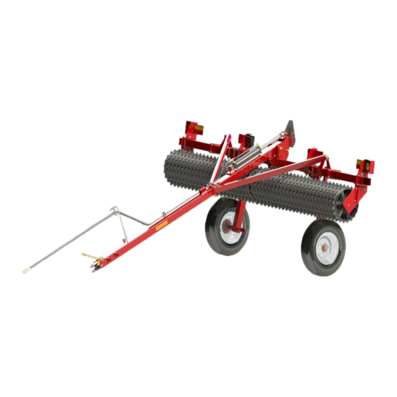
- Page 1 Transport Pulverizer P Series 10’ through 16’ PT Series 10’ through 20’ Operator’s Manual LANDOLL CORPORATION 1900 North Street Marysville, Kansas 66508 (785) 562-5381 800-428-5655 ~ WWW.LANDOLL.COM 189rev0713 9J017...
-
Page 3: Table Of Contents
Table of Contents Introduction and Safety Information Introduction ..............1-1 Description of Unit . - Page 4 Operation Operation of the Transport Pulverizer ..........3-1 Field Operation .
-
Page 5: Introduction And Safety Information
Failure to comply with this warning can result in within 10 days of retail purchase, using the Landoll to the personal injury or death, damage Corporation Ag Products on-line registration process. -
Page 6: Understanding Safety Statements
INTRODUCTION AND SAFETY INFORMATION When applying decals to the implement, be sure to clean NOTE the surface to remove any dirt or residue. Where possible, sign placement should protect the sign from Investigation has shown that nearly 1/3 of all farm abrasion, damage, or obstruction from mud, dirt, oil etc. -
Page 7: Maintenance Safety
INTRODUCTION AND SAFETY INFORMATION Maintenance Safety When inflating tires, use a clip-on chuck and extension hose long enough to allow you to stand to one side, not in • Block the implement so it will not roll when working on front of or over the tire assembly. - Page 8 INTRODUCTION AND SAFETY INFORMATION Figure 1-3: Safety Decals 9J017...
- Page 9 INTRODUCTION AND SAFETY INFORMATION Figure 1-4: Safety Decal Locations...
- Page 10 INTRODUCTION AND SAFETY INFORMATION Table provided for general use. NOTES: 9J017...
-
Page 11: Assembly
Chapter 2 Assembly Frame Assembly CAUTION NOTE Do not work on or under this machine unless securely blocked and supported by a hoist or “Left” and “Right” refer to directions seen as if standing tractor or by other sufficient means! behind the machine and facing in the direction of forward travel. - Page 12 ASSEMBLY 3. If a center bracket is included with the machine, it 4. Place the center bracket at the center of the center must be installed next. Start by clamping the center frame. Fasten it using 5/8" x 5-1/2" deep U-bolts or, brackets between the pair of angle iron clips.
-
Page 13: End Brackets Installation
ASSEMBLY End Brackets Installation: 3. Attach Light Mount Brackets, using 5/8-11 x 6-11/16 x 5 1/2 U-bolts and 1/2-13 Flange Nuts. (On 18’ - 20’ 1. Start with the right hand end plate and the two angle machines 3K320 Strap, 1J696 Bolt, Washer 9C134 members required, See Figure 2-3. -
Page 14: Wheel And Axle Assemblies (Wheel Gangs) Installation
ASSEMBLY Wheel And Axle Assemblies (Wheel female (square bore bearing assemblies). See Figure 2-4 for male, See Figure 2-5 for female. Gangs) Installation 2. If the wheel gang has male hardware, slide the wheel gang end-wise toward the center bracket, IMPORTANT mating the stub shaft with the bearing on the center Keep the Wheel Gang Assemblies in close alignment... - Page 15 ASSEMBLY Figure 2-5: Wheel and Axle Installation - 2 of 4 6. If the wheel gang has female hardware, slide the 7. Install right hand end plate assembly on the center wheel gang end-wise, toward the center bracket, frame tube: use 5/8-11 x 5 1/2” deep x 6 11/16” mating the square bore bearing with the stub shaft on center U-bolt, 5/8”...
- Page 16 ASSEMBLY 8. Position and block up the center frame against the end of the drawbar, lining up the holes in the drawbar with the center frame mounting bracket and pin them together. See Figure 2-7. Figure 2-7: Wheel and Axle Installation - 4 of 4 9J017...
-
Page 17: Optional Sprocket 4K775 Installation
ASSEMBLY Optional Sprocket 4K775 Installation 1. Position the Sprocket between each 3J619 wheel so it rides on top of wheels. See Figure 2-8. 2. Make sure the sprocket does not bind. NOTE Sprocket 4K775 is an option used only with 3J619 Wheel. -
Page 18: Drawbar Hitch Installation
ASSEMBLY Drawbar Hitch Installation 3. Attach the jack to the round tube near the hitch with the pin and chain. 1. Mount the flat spring to the bottom of the drawbar 4. Using a 5/8-11 x 2” Screw and 5/8” Lockwasher and with 3/8-16 x 1”... -
Page 19: Drawbar Brace Installation
ASSEMBLY Drawbar Brace Installation 1. Using Grade 5, 1-8 x 5 1/2” Screws and 1” Flat Washers and Nuts, attach the proper end of each brace to the center frame. NOTE 2. Using Grade 5, 1/2-13 x 7 1/2” Machine Bolts, 1/2” Both braces and ends are identical. -
Page 20: Wheel Arms To Center Frame Installation
ASSEMBLY Wheel Arms to Center Frame 2. Mount the wheels to the axle hubs with the 1/2” Wheel Bolts provided. Installation 1. Using 5/8-11 x 5 1/2” x 6 11/16” center U-bolts, 5/8” CAUTION Lockwashers and Nut, attach the wheel arms to the Wheel arms should always be equidistant from center frame. -
Page 21: Hydraulic Cylinder Installation
ASSEMBLY Hydraulic Cylinder Installation WARNING Avoid the hazard by relieving pressure before disconnecting hydraulic lines. Escaping fluid under pressure can be nearly invisible and have enough force to penetrate the On most tractors this can be done by putting the valve skin causing serious injury. -
Page 22: Hydraulic Hose Installation
ASSEMBLY 1. Turn the O-Ring end of Restrictor into the cylinder Hydraulic Hose Installation: port. Install Elbow Fitting onto Restrictor. See Figure 2-13. 2. Attach longer hose to Cylinder rod end Elbow Fitting and the shorter hose to Cylinder base end Elbow Fitting. -
Page 23: Series 10'-20' Models Led Lamp And Harness Installation
ASSEMBLY PT Series 10’-20’ Models LED Lamp 14. Route the remaining left and right 2 plug cords along the left and right top of frame and connect into each and Harness Installation Amber LED Lamp. 15. Layout the 7 Pin Harness and attach the harness to NOTE the Light Module. - Page 24 ASSEMBLY Figure 2-14: LED Schematic 2-14 9J017...
- Page 25 ASSEMBLY Figure 2-15: PT-Series 10’-20’ LED Warning Lights Installation Dimensions Figure 2-16: LED Lamp Adjustment 2-15...
- Page 26 ASSEMBLY Figure 2-17: LED Modules and Brackets 2-16 9J017...
- Page 27 ASSEMBLY Figure 2-18: PT 10’ LED Warning Lights Installation 2-17...
- Page 28 ASSEMBLY Figure 2-19: PT 12’-16’ LED Warning Lights Installation 2-18 9J017...
- Page 29 ASSEMBLY Figure 2-20: PT 17’-20’ LED Warning Lights Installation 2-19...
-
Page 30: P Series10'-16' Models Led Lamp And Harness Installation
ASSEMBLY P Series10’-16’ Models LED Lamp and 14. Adjust the LED lamp angles so LED’s are vertical. Adjustment is provided to compensate for high Harness Installation drawbar heights if used as a companion tool or lower heights if towed directly behind a tractor. See NOTE Figure 2-16. - Page 31 ASSEMBLY Figure 2-21: P-Series 10’-16’ LED Warning Lights Installation Dimensions 2-21...
- Page 32 ASSEMBLY Figure 2-22: P Series 10’-16’ LED Warning Lights Installation 2-22 9J017...
-
Page 33: 8J001 Wheel Scraper Installation-Optional
ASSEMBLY 8J001 Wheel Scraper Installation- 2. Assemble one bracket at each end of frame and assemble the remaining two brackets such that the Optional space between all brackets is approximately equal. 1. Attach scraper brackets to frame tube of Transport 3. -
Page 34: 3J619 And 8C988 Wheels Scraper Installation - Optional
ASSEMBLY 3J619 and 8C988 Wheels Scraper IMPORTANT Installation - Optional Prior to installing the scrapers ensure the pulverizer 1. Attach the scraper brackets. (three required for the 4” is placed on the ground. Otherwise scraper to wheel x 6” frame tube of pulverizer) Put middle bracket to clearance will be affected. -
Page 35: V-Wheel Scraper Installation - Optional
ASSEMBLY V-Wheel Scraper Installation - Scraper Brackets with previously removed eight 1/2-13 Locknuts. Tighten all hardware. Optional NOTE With the Rollers on level ground, Place 5/8-11 U-bolts over the center and outer frame cross tubes and through Allow a small amount of clearance, approximately 1/4” the Scraper Brackets. - Page 36 ASSEMBLY Table provided for general use. NOTES: 2-26 9J017...
-
Page 37: Operation
Slow down when operating on rocky soil. This chapter will cover the basic operation and Transporting procedures for the Landoll Brillion Transport Pulverizer. Be sure to read and understand the Safety Procedures To prepare the machine for transport, hitch pulverizer to and Cautions starting on page 1-1. -
Page 38: Parking The Transport Pulverizer
OPERATION Parking the Transport Pulverizer The best way to park the pulverizer is to place the machine in its desired location. Once there, remove the transport pin and place it in the rear-most hole. Lower the machine to the ground. Place blocks in front and behind the pulverizer to prevent it from rolling when unhitched. -
Page 39: Maintenance
Chapter 4 Maintenance General Torque Specifications This chart provides tightening torques for general purpose applications when special torques are not specified on process or drawing. Assembly torques apply to plated nuts and capscrews assembled without supplemental lubrication (as received condition). They do not apply if special graphite moly-disulfide or other extreme pressure lubricants are used. -
Page 40: Hydraulic Fitting Torque Specifications
MAINTENANCE Hydraulic Fitting Torque Specifications 37 degree JIC, ORS, &ORB (REV. 10/97 This chart provides tightening torques for general purpose applications when special torques are not specified on process or drawing. Assembly torques apply to plated nuts and capscrews assembled without supplemental lubrication (as received condition). They do not apply if special graphite moly-disulfide or other extreme pressure lubricants are used. -
Page 41: Lubrication
MAINTENANCE Lubrication WARNING NOTE Do not lubricate machine while machine is in motion. If any guards are removed for lubricating, It is good maintenance practice to check all bolts for they must be replaced before operating. tightness during regular lubrications. Tighten any fasteners that may have loosened during operations. -
Page 42: Clamp Tightening Procedure
MAINTENANCE Clamp Tightening Procedure The tightening procedure and torque requirement is critical in keeping in keeping the clamp tight and also has a significant affect on the bearing life of the axles with internal bearings. Clamp Tightening Procedure: 5. Tighten set screws to 37 ft/lbs (Some clamps do not have set screws.) 1. -
Page 43: General Reference And Specifications
Chapter 5 General Reference and Specifications Table 5-1: PDT Series 10’ - 14’ PDT Series Specifications PDT-10 PDT-12 PDT-14 Approximate Weight 1,828 lbs. (823 kg) 2,050 lbs. (923 kg) 2,262 lbs. (1,018 kg) Working Width 10 ft. 0 in. (3 m) 12 ft. - Page 44 GENERAL REFERENCE AND SPECIFICATIONS Table 5-2: PDT Series 16’ - 20’ PDT Series Specifications PDT-16 PDT-18 PDT-20 Approximate Weight 2,472 lbs. (1,112 kg) 2,811 lbs. (1,265 kg) 3,041 lbs. (1,368 kg) Working Width 16 ft. 0 in. (4.8 m) 18 ft. 0 in. (6.48 m) 20 ft.
- Page 45 GENERAL REFERENCE AND SPECIFICATIONS Table 5-3: PXT Series 10’ - 14’ PXT Series Specifications PXT-10 PXT-12 PXT-14 Approximate Weight 2,157 lbs. (971 kg) 2,498 lbs. (1,124 kg) 2,791 lbs. (1,256 kg) Working Width 10 ft. 0 in. (3 m) 12 ft. 0 in. (3.6 m) 14 ft.
- Page 46 GENERAL REFERENCE AND SPECIFICATIONS Table 5-4: PXT Series 16’ - 18’ PXT Series Specifications PXT-16 PXT-18 Approximate Weight 3,123 lbs. 1,405 kg) 3,489 lbs. (1,570 kg) Working Width 16 ft. 0 in. (4.8 m 18 ft. 0 in. (5.4 m) Transport Width 17 ft.
- Page 47 GENERAL REFERENCE AND SPECIFICATIONS Table 5-5: PDCT Series 10’ - 14’ PDCT Series Specifications PDCT-10 PDCT-12 PDCT-14 Approximate Weight 1,707 lbs. (768 kg) 2,027 lbs. (912 kg) 2,284 lbs. (1,028 kg) Working Width 10 ft. 0 in. (3 m) 12 ft. 0 in. (3.6 m) 14 ft.
- Page 48 GENERAL REFERENCE AND SPECIFICATIONS Table 5-6: PDCT Series 16’ - 18’ PDCT Series Specifications PDCT-16 PDCT-18 Approximate Weight 2,496 lbs. (1,123 kg) 2,720 lbs. (1,224 kg) Working Width 16 ft. 0 in. (4.8 m 18 ft. 0 in. (5.4 m) Transport Width 17 ft.
- Page 49 GENERAL REFERENCE AND SPECIFICATIONS Table 5-7: POT Series 10’ - 15’ POT Series Specifications POT-10 POT-12 POT-14 POT-15 Approximate Weight 2,052 lbs. (931 kg) 2,254 lbs. (1,014 kg) 2,500 lbs. (1,125 kg) 2,642 lbs. (1,189 kg) Working Width 10 ft. 0 in. (3 m) 12 ft.
- Page 50 GENERAL REFERENCE AND SPECIFICATIONS Table 5-8: POT Series 16’ - 20’ POT Series Specifications POT-16 POT-17 POT-18 POT-20 Approximate Weight 2,742 lbs. (1,234 kg) 3,035 lbs. (1,366 kg) 3,135 lbs. (1,411 kg) 3,387 lbs. (1,524 kg) Working Width 16 ft. 0 in. (4.8 m) 17 ft.
- Page 51 GENERAL REFERENCE AND SPECIFICATIONS Table 5-9: PGT Series 10’ - 16’ PGT Series Specifications PGT-10 PGT-12 PGT-14 PGT-16 Approximate Weight 1,887 lbs. (849 kg) 2,174 lbs. (978 kg) 2,413 lbs. (1,086 kg) 2,691 lbs. (1,211 kg) Working Width 10 ft. 0 in. (3 m) 12 ft.
- Page 52 GENERAL REFERENCE AND SPECIFICATIONS Table 5-10: PVT Series 10’ - 15’ PVT Series Specifications PVT-10 PVT-12 PVT-14 PVT-15 Approximate Weight 2,223 lbs.(1008 kg.) 2,565 lbs. (1163 kg.) 2,844 lbs.(1290 kg.) 3,006 lbs.(1363 kg.) Working Width 10 ft. 0 in. (3 m) 12 ft.
- Page 53 GENERAL REFERENCE AND SPECIFICATIONS Table 5-11: POT Series 16’ - 20’ PVT Series Specifications PVT-16 PVT-17 PVT-18 PVT-20 Approximate Weight 3,122 lbs.(1416 kg.) 3,343 lbs. (1516 kg.) 3,460 lbs. (1569 kg.) 3,844 lbs. (1744 kg.) Working Width 16 ft. 0 in. (4.8 m) 17 ft.
- Page 54 GENERAL REFERENCE AND SPECIFICATIONS Table provided for general use. NOTES: 5-12 9J017...
- Page 55 Document Control Revision Log: Date Revision Improvement(s) Description and Comments 11/2007 189rev1107 Updated Manual 05/2012 189rev0512 Improved Drawings, Translated to Landoll Format 07/2013 189rev0713 Added LED Warning Lights...
- Page 56 Equipment from Landoll Corporation is built to exacting standards ensured by ISO 9001 registration at all Landoll manufacturing facilities. Transport Pulverizer P Series 10’ through 16’ PT Series 10’ through 20’ Operator’s Manual Re-Order Part Number 9J017rev0713 LANDOLL CORPORATION 1900 North Street...
Need help?
Do you have a question about the Brillion P Series and is the answer not in the manual?
Questions and answers