
Related Manuals for Landoll Brillion SL10


Summary of Contents for Landoll Brillion SL10
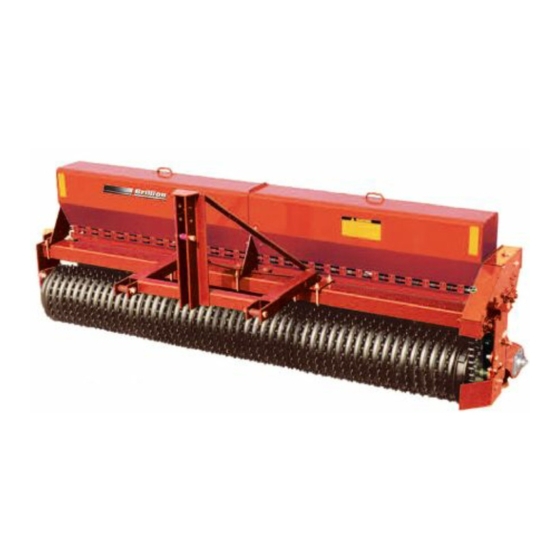
- Page 1 Turfmaker Seeder Models SL10/SL12 SLP8/SLP10/SLP12 Operator’s Manual LANDOLL COMPANY, LLC 1900 North Street Marysville, Kansas 66508 (785) 562-5381 800-428-5655 ~ WWW.LANDOLL.COM 1P342-0621...
- Page 2 Manuals for Turfmaker Seeder, Models SL10/SL12 and SLP8/SLP10/SLP12 Manual Number Manual Name 1P342 Operator’s Manual 1P341 Parts Manual...
-
Page 3: Table Of Contents
Table of Contents Safety Information Introduction ..............1-1 Description of Unit . - Page 4 Coil Tine Track Remover Kit - Optional ......... . . 2-28 Turfmaker Sprockets - Optional .
-
Page 5: Safety Information
10 days of retail purchase, using the Landoll or its components and inferior operation. Company, LLC Ag Products on-line registration process. Please refer to the Ag Products Policy and Procedures Manual, accessible at www.landoll.com... -
Page 6: Safety
SAFETY INFORMATION Safety • When applying decals to the machine, be sure to clean the surface to remove any dirt or residue. Where possible, sign placement should protect the sign from NOTE abrasion, damage, or obstruction from mud, dirt, oil Investigation has shown that nearly 1/3 of all farm etc. -
Page 7: Safety Instructions For Towing Vehicles
SAFETY INFORMATION Safety Instructions for Towing • Make sure all moving parts have stopped and all system pressure is relieved. Vehicles • Understand the procedure before doing the work. Use The maximum travel speed is the lesser of proper tools and equipment. •... -
Page 8: Safety Chain
SAFETY INFORMATION Safety Chain 3. Attach the chain to the Tractor Drawbar Support or specified anchor location. Never attach the chain to 1. Use a safety chain to help control drawn machinery an intermediate support. Allow only enough slack in should it separate from the Tractor Drawbar. -
Page 9: Decals
SAFETY INFORMATION Decals Turfmaker 4K401 ITEM 1 ITEM 2 4K039 4K388 ITEM 3 ITEM 8 ITEM 4 528933 528934 528938 CAUTION WARNING MOVING MACHINES CAN CAUSE INJURY. KEEP AWAY! 1. KEEP AWAY FROM MOVING TRACTORS OR IMPLEMENTS. KEEP OTHERS AWAY. 2. - Page 10 SAFETY INFORMATION Figure 1-4: Decal Placement, Hitch 1P342-0621...
- Page 11 SAFETY INFORMATION Figure 1-5: Decal Placement, 8FT Model 1P342-0621...
- Page 12 SAFETY INFORMATION Figure 1-6: Decal Placement, 10FT Model 1P342-0621...
- Page 13 SAFETY INFORMATION Figure 1-7: Decal Placement, 12FT Model 1P342-0621...
- Page 14 SAFETY INFORMATION Table provided for general use. NOTES: 1-10 1P342-0621...
-
Page 15: Assembly
Chapter 2 Assembly IMPORTANT CAUTION All harnesses must be firmly attached to machine Do Not Work On Or Under This Machine Unless frame members, so they don’t sag or become torn Securely Blocked And Supported By A Hoist Or loose by field debris. -
Page 16: 3-Pt Seeder Assembly
ASSEMBLY 3-PT Seeder Assembly CAUTION When shipped, seeder comes assembled except for Do not disengage pin unless seeder is fully Lights and 3-PT Hitch. attached to a tractor. Seeder may be rear-heavy 1. Support Seeder Assembly with a hoist or by similar and tip backward on frame. - Page 17 ASSEMBLY Frame Nut,5/8-11 Lock Washer,5/8 Hose Clamp Manual Holder Op3PtHitch U-Bolt,5/8-11 3-PT Hitch Figure 2-5: Attach 3-PT Hitch 1P342-0621...
-
Page 18: Pull Type Seeder Assembly
ASSEMBLY Pull Type Seeder Assembly 4. Install Manual Holder to Drawbar with Hose Clamps. 5. 8FT Seeders: Install SMV Mount to Seed Box Frame 1. Untie the two rolled up Drawbar Hydraulic Hoses with 1/2-13 U-Bolt, Lock Washers and Nuts. See near the center of the Frame Tube. -
Page 19: Tire And Wheel Installation
ASSEMBLY Tire and Wheel Installation WARNING Use a torque wrench to assure proper torque. Insufficient torque can cause stud breakage and damage the wheel pilots. Over torque can stress the Bolts and strip the threads. NOTE The tire/wheel assembly is mounted with the valve stem facing outward from Hub and Spindle. -
Page 20: Hydraulic Installation
ASSEMBLY Hydraulic Installation Hydraulic Assembly 1. Restrictors installed in Cylinder Ports, connect 45 Degree Fitting so they are free to swivel. Connect top WARNING Hydraulic Hose to the Cylinder Base and bottom Hydraulic Hose to the Cylinder Rod End. Position the Escaping fluid under pressure can be nearly Hydraulic Hoses so that the Cylinder Base End invisible and have enough force to penetrate the... - Page 21 ASSEMBLY Hose Clamp Pair Frame Hose Assembly Bolt,1/4-20 x 1-1/2 Top Plate Drawbar Figure 2-11: Drawbar Hydraulic Hoses 1P342-0621...
- Page 22 ASSEMBLY Table provided for general use. NOTES: 1P342-0621...
-
Page 23: Purge The Hydraulic Lift System
ASSEMBLY Purge the Hydraulic Lift System Bolt,5/8-11 Flat Washer,5/8 The Hydraulic system is not filled with oil and should be purged of air before transporting and field operations. Locknut,5/8-11 Lift Circuit approximate oil requirement: 0.4 gallons. 1. Carefully Hitch the Seeder to the Tractor and connect the Hydraulic Lift Hoses. -
Page 24: Warning Lamp Installation, 8Ft And 10Ft
ASSEMBLY Warning Lamp Installation, 8FT IMPORTANT and 10FT All Harnesses must be firmly attached to Machine Frame members or Hydraulic Hoses so they do not NOTE sag or become torn loose by field debris. 13. Attach the SMV sign to the SMV Mount located on 8FT 3-PT model is shown, 8FT Drawbar and 10FT 3-PT the center on the Front Frame with 5/16-18 x 1 Bolts, and Drawbar models are similar. - Page 25 ASSEMBLY Amber Lamp Locknut,1/4-20 Bolt, Light Bracket 1/4-20x1-1/4 Bolt,1/2-13x1-1/4 Lamp Lock Washer,1/2 Nut, 1/2-13 Bolt,5/16-18x1 Mount Locknut,5/16-18 Tie Wrap Flat Washer,5/16 SMV Mount Bolt,1/4-20x1 7-Pin Harness Connector Holder Lamp Harness Flat Washer,1/4 Locknut,1/4-20 Locknut,1/4-20 Light Module Bolt, 1/4-20x1-1/2 Amber Lamp Lamp Tie Wrap Nut,3/8-16...
-
Page 26: Warning Lamp Installation, 12Ft
ASSEMBLY Warning Lamp Installation, 12FT IMPORTANT All Harnesses must be firmly attached to Machine NOTE Frame members or Hydraulic Hoses so they do not 12FT Drawbar model is shown, 3-PT models similar. sag or become torn loose by field debris. 1. - Page 27 ASSEMBLY Amber Lamp Locknut,1/4-20 Bolt, 1/4-20x1-1/4 Light Bracket Bolt,1/2-13x1-1/4 Lock Washer,1/2 Mount Nut, 1/2-13 Bolt,1/4-20x1-1/4 Flat Washer,5/16 Locknut, Tie Wrap 5/16-18 Connector Bolt,5/16-18x1 Lamp Light Holder Locknut,1/4-20 Bolt,1/4-20x1 Locknut, 1/4-20 Flat Washer, Lamp 7-Pin Harness Harness Locknut,1/4-20 Locknut,1/4-20 Module Bracket Light Bolt, Module...
-
Page 28: Acre Meter Kit - Optional
ASSEMBLY Acre Meter Kit - Optional 3. Attach the Pick-Up Switch Bracket to the front of the Transmission with 3/16 x 1-1/4 Bolts, Lock Washers P/N 5K745 - Transmission w/o Clutches and Nuts. 4. Attach the Pick-Up Switch to the top of the Pick-Up NOTE Switch Bracket/Mount with two #8-32 x 1-1/4 The Acre Meter Kit consists of three main parts, the Acre... - Page 29 ASSEMBLY Magnet Wheel Assembly Magnet Pick-Up Switch Pick-Up Switch Bracket SIDE VIEW 1/8" Figure 2-19: Pick-Up Switch Positioning 7. Attach the Pick-Up Switch Ground Wire to the small hole in the Pick-Up Switch Bracket with a #6-32 x 1/2 Screw, removing paint under the wire connector to assure a good electrical ground connection.
-
Page 30: Seed Shaft Sensor Kit - Optional
ASSEMBLY Seed Shaft Sensor Kit - Optional 3. Identify the seed cups on either side of the Magnet Wheel Assembly and remove the 1/4-20 hardware. 1. Remove the two #10 x 24 x 3/4" Self Tapping Screws 4. Insert Sensor into Shaft Sensor Bracket slot. from the Magnet Wheel Assembly. - Page 31 ASSEMBLY Shaft Sensor Bracket SeedShaftSensorDim Seed Shaft Magnet Wheel Sensor Assembly Magnet 1/8" Max Figure 2-21: Seed Shaft Sensor Mounting Dimension - Seed Meter 1P342-0621 2-17...
-
Page 32: Seed Shaft Sensor Schematic
ASSEMBLY Seed Shaft Sensor Schematic 5. On left side seal the plug that says Electric Clutch using a 2-Pin Shroud and Cavity Plug to protect it Mount Console with Clutch Control on Tractor. from the environment. See Figure 2-22. 1. Route Console Harness with 9-Pin Connector to the 6. - Page 33 ASSEMBLY Table provided for general use. NOTES: 1P342-0621 2-19...
-
Page 34: Agitator Kit - Optional
ASSEMBLY Agitator Kit - Optional 9. Tighten locking collars in direction of rotation (counter-clockwise when viewed from the right end of 1. Remove knock-outs for 3/4" flangette bearings. machine). These are located at each end and center of Seed 10. Rotate agitator assembly to be sure it turns freely. Box assembly. - Page 35 ASSEMBLY Figure 2-25: 8FT Agitator 1P342-0621 2-21...
- Page 36 ASSEMBLY Figure 2-26: 10FT Agitator 2-22 1P342-0621...
- Page 37 ASSEMBLY Figure 2-27: 12FT Agitator 1P342-0621 2-23...
-
Page 38: Scraper Kit - Optional
ASSEMBLY Scraper Kit - Optional 2. Attach the LH and RH Angle Brackets to the Brackets with 1/2-13 x 3-1/4 x 4-9/16 U-Bolts, Lock Washers and Nuts. Do not tighten at this time. IMPORTANT 3. Attach the Scraper Angle to the LH and RH Angle Cannot be used with Coil Tine Track Remover Kit. - Page 39 ASSEMBLY U-Bolt,1/2-13 x Lock Washer,1/2 7-1/2 x 4-1/2 Nut,1/2-13 Bracket U-Bolt,1/2-13 x Nut,3/8-16 Center 3-1/4 x 4-9/16 Scraper Lock Washer,3/8 Seeder Frame Flat Washer,3/8 Tube Scraper LH Angle Bracket Carriage Bolt, 3/8-16 x 1-1/4 Scraper Angle LH Angle Bracket SeederScraperKit Lock Washer,1/2 Nut,1/2-13 U-Bolt,1/2-13 x...
-
Page 40: S-Tine Tire Track Remover Kit - Optional
ASSEMBLY S-Tine Tire Track Remover Kit - 2. Attach the Tooth Tube to the S-Tine Brackets approximately 5 inches from each end of the Tooth Optional Tube with Straps, 1/2-13 x 6 Bolts, Lock Washers and Nuts. See Figure 2-31. IMPORTANT 3. - Page 41 ASSEMBLY Lock Washer,1/2 U-Bolt,1/2-13 x Nut,1/2-13 7-1/2 x 4-1/2 S-Tine Bracket Strap Clamp Nut,1/2-13 Carriage Bolt, Lock Washer,1/2 7/16-14 x 3-1/2 Bolt,1/2-13 x 6 Tooth Tube Locknut,7/16-14 S-Tine Reversible Point Flange Locknut, SeederS-TineTrackRemoverKit 3/8-16 Duck Foot Point Plow Bolt 3/8-16 X 1-3/4 Seeder Frame Tube Figure 2-31: S-Tine Track Remover Kit - Optional...
-
Page 42: Coil Tine Track Remover Kit - Optional
ASSEMBLY Coil Tine Track Remover Kit - Optional IMPORTANT Cannot be used with the Scraper Kit 1. Slide the Coil Tines onto the Round Bar so that the straight leg is frontward. See Figure 2-32. 2. Mount an Arm Weldment and a Coil Tine to the Round Bar second hole from the right end and the third hole from the left end with 3/8-16 x 3 Bolts, Flat Washers, Lock Washers and Nuts. - Page 43 ASSEMBLY Bolt,3/8-16 x 1-1/4 Hair Pin Cotter Adjusting Angle Place Chain in Adjusting Angle Slot Clevis Pin, 1/2 x 1-1/4 Flat Washer,3/8 Lock Screw Nut,1/2-13 Chain Lock Washer,3/8 Lock Washer,1/2 Nut,3/8-16 Bracket Bolt, Seeder Frame 1/2-13 x 1-3/4 Tube Bolt, Bolt, 3/8-16 x 2-1/2 3/8-16 x 3...
-
Page 44: Turfmaker Sprockets - Optional
ASSEMBLY Turfmaker Sprockets - Optional Turfmaker Sprockets provide extra traction in certain soil types. See your Landoll/Brillion dealer for more information. 1. Position the Turfmaker Wheel Spacer between each 4C689 Sand Wheel. See Figure 2-33. 2. At the end of the process slide a Half Wheel onto the axle next to the last Wheel Spacer. -
Page 45: Operation
Chapter 3 Operation DANGER DANGER Never allow anyone to ride on the seeder at any Always lock the tractor drawbar in the center time. Allowing a person to ride on the machine position when transporting the unit. Failure to do can inflict serious personal injury or death to that so can result in serious injury or death and cause person. -
Page 46: Tractor Preparation
OPERATION Tractor Preparation DANGER The Turfmaker - Alfalfa Seeder is available as a Do not allow any bystanders to stand between Pull-Type or 3-PT mounted version. the tractor and the machine while backing up to A Pull-Type seeder is equipped to be pulled by a tractor the machine. - Page 47 OPERATION 1" Pin 24" 1-1/8" Pin Category 2 Free Link 1-1/4" Bushing 1" Pin 1-7/16" Bushing 15" 1-1/8" Pin Category 2 Quick Coupler Op LargeSeeder3PtHitch 1-1/4" Bushing 1" Pin 1-7/16" Bushing 19" 1-1/8" Pin Category 3 Narrow Quick Coupler Figure 3-1: 3-Point Hitch 1P342-0621...
-
Page 48: Attaching/Detaching 3-Pt Hitch Seeder
OPERATION Attaching/Detaching 3-PT Hitch Seeder Klik Pin WARNING Disengaged To prevent the machine from tipping backward on the frame, disengage parking pin only when the seeder is fully attached to the tractor. Be sure to observe the following sequences. Parking Pin Klik Pin Figure 3-3: Parking Pin Disengaged... -
Page 49: Tractor Preparation/Attaching Of Pull Type Seeder
OPERATION Tractor Preparation/Attaching of Locknut, 3/4-10 Pull Type Seeder Drawbar Tractor Drawbar Support DANGER Do not allow any bystanders to stand between Flat Washer, 3/4" the tractor and the machine while backing up to the machine. 1. Align the Tractor Drawbar with the machine. Raise or lower the Drawbar, as needed, using the Jack. -
Page 50: Attaching/Detaching Pull Type Seeder
OPERATION Attaching/Detaching Pull Type Seeder Frame Cylinder Attaching the Seeder for Field Operations: Seeder parked lowered Hair Pin 1. Attach Seeder to the Tractor. Cotter 2. Raise the Seeder fully to extend the Hydraulic Lift Cylinders and rotate the Transport Locks in the engaged position over the Cylinder Rod. -
Page 51: Hydraulic Lift System
OPERATION Hydraulic Lift System The Seeder is equipped with a Hydraulic Lift System to raise and lower the unit in the field. WARNING Escaping hydraulic fluid can cause serious personnel injury. Relieve system pressure before repairing, adjusting, or disconnecting. Wear proper hand and eye protection when searching for leaks. -
Page 52: Seed Box Seed Rate Adjustment
OPERATION Seed Box Seed Rate Adjustment IMPORTANT If equipped, the Clutch must be disengaged when WARNING Seed Shafts are turned manually for Calibration. Seed Rate Charts specific to Seeder Model are located • To Prevent damage to seed meters, do not inside the Seed Box Cover and in this manual. - Page 53 OPERATION Figure 3-11: Seed Rate Chart NOTE Brillion assumes no liability pertaining to seeding rates achieved with this seeder. Rates listed are general in nature and should be used as starting points only. Seed varieties and blends listed represent those calibrated through in-house test meters. Variations in actual rates may be realized due to differences in seed lots.
-
Page 54: Transmission Drive Bolt
OPERATION Transmission Drive Bolt Calibration for Unlisted Seeds Brillion/Landoll assumes no liability pertaining to Seeding NOTE Rates achieved with this Seeder. Rates listed are general in nature and should be used as starting points only. #550 Chain connects Front Roller #550 Chain 6 Tooth... - Page 55 OPERATION Tightener 6 Tooth #A550 Driver 13 Tooth 15/16 Hex Idler 37 Tooth Driven 13 Tooth Driver (26 Tooth Optional) Figure 3-13: Transmission Drive 1P342-0621 3-11...
-
Page 56: Speed-Up Kit - Optional
OPERATION Speed-Up Kit - Optional 4. Remove the Locking Collar from left side of the Front Transmission Shaft. Seed rates can be doubled by using a 26-Tooth Sprocket 5. Remove Bearing Bolts from right side of the Front and following the procedure below: Transmission Shaft. -
Page 57: Loup Acre Meter Kit - Optional (After 05/15/2012)
OPERATION Loup Acre Meter Kit - Optional To clear the total acre count, press and hold the UP and DOWN buttons for two seconds. If a password has been (After 05/15/2012) entered, you will not be able to clear the total acre count. Total acres will count from.1 to 99999 acres. -
Page 58: Loup Acre Meter Kit - Optional (Before 05/15/2012)
OPERATION If the display shows “Ent”: You must enter your 6. Press the function button to set the width. (If screen password using the UP and DOWN buttons. When your goes blank before you press the function button, password is displayed, press the /FUNC button to test repeat steps 4 and 5). - Page 59 OPERATION Table 3-1: Acre Meter Settings (After 05/15/2012) MODEL PULSES WIDTH SSPT604 SSP4 SSP5 SSP6 SSP8 SSBP8 SSB8 SSP10 SSBP10 SS10 SSB10 10.0 SSP12 SSBP12 SS12 SSB12 12.0 SSP16 SS16 16.0 SSP108 SS108 SSP110 SS110 10.0 SSP112 SS112 12.0 SSP208/2081 SS208/2081 SSP210/2101 SS210/2101...
- Page 60 OPERATION Table 3-2: Acre Meter Settings (Prior to 05/15/2012) MODEL PULSES WIDTH SSP T604 SSP4 SSP5 SSP6 SSP8 SSP10 SS10 SSP12 SS12 SSP108 SS108 SSP110 SS110 SSP112 SS112 SSP208 SSP2081 SS208 SS2081 SSP210 SSP2101 SS210 SS2101 SSP212 SSP2121 SS212 SS2121 SSP308 SS308 SSP310...
-
Page 61: Seed Shaft Sensor Console With Clutch Control - Optional
OPERATION Seed Shaft Sensor Console with 3. When towing equipment in combination, the maximum equipment ground speed shall be limited Clutch Control - Optional to the lowest specified ground speed of any of the towed machines. Basic Operation: Maximum transport speed shall be the lesser of During normal operation the Console LED for the Seed travel speed specified in the operator's manual, Shaft will not be illuminated. - Page 62 OPERATION 9. Plug in the safety lights to the tractor 7-Pin Connector. 10. Fully raise the Seeder Hydraulic Lift and 3-PT Hitch. 11. Install transport lock. Do not depend solely on implement hydraulics for transport. See “Transport Lock Engaged” on Page 3-5. ...
-
Page 63: Maintenance
Chapter 4 Maintenance General Torque Specifications (rev. 4/97) This chart provides tightening torques for general purpose applications when special torques are not specified on process or drawing. Assembly torques apply to plated nuts and capscrews assembled without supplemental lubrication (as received condition). They do not apply if special graphite moly-disulfide or other extreme pressure lubricants are used. -
Page 64: Hydraulic Fitting Torque Specifications
MAINTENANCE Hydraulic Fitting Torque Specifications 37 degree JIC, ORS, &ORB (REV. 10/97 This char t provides tightening torques for general purpose applications when special torques are not specified on process or drawing. Assembly torques apply to plated nuts and capscrews assembled without supplemental lubrication (as received condition). They do not apply if special graphite moly-disulfide or other extreme pressure lubricants are used. -
Page 65: Tires
MAINTENANCE Tires 10. Slide the Single Lip Seal to the Hub and install the Seal in the Hub. Seeder recommended Tire Size: 11. Install a new Cotter Pin and re-install the Hub Cap. 9.5L-15 - 8 Ply Rating 12. Grease Wheels Hubs every 50 hrs. See Figure 4-2. Tire Inflation Pressure: 44 PSI When Re-Installing 1/2-20 x 1 Wheel Bolts tighten to Lubrication... - Page 66 MAINTENANCE Pull Type Frame Wheel Arm Tire and Wheel Assembly Wheel Hub Repack Annually Rear Roller Bearing Rear Arm Rear Roller Bearing Pull Type Seeder Frame Front Roller Bearing SL2 OpGrease 3-PT Seeder Frame Front Roller Bearing Figure 4-2: Lube Points 1P342-0621...
-
Page 67: Hydraulic Maintenance
MAINTENANCE Hydraulic Maintenance IMPORTANT To maximize seed germination, peaks on Rear Roller IMPORTANT Wheels should line up with valleys on the Front Lower the unit to the ground, and relieve hydraulic Roller Wheels. This will require adjusting the Clamp pressure before attempting to service any hydraulic Bands on each end of the Rear Roller Drum and component. -
Page 68: Chain Tension
MAINTENANCE Chain Tension Clevis Drawbolt Locknut To adjust the Transmission Chain, loosen the 5/8" Idler #40 Chain Sprocket Axle Bolt and then adjust the Clevis Drawbolt Locknut to obtain about 1/8" - 1/4" sag. Re-tighten Idler Clevis Sprocket Axle Bolt. Be careful not to over-tighten this Drawbolt chain. -
Page 69: Seed Meter Adjustment
MAINTENANCE Seed Meter Adjustment IMPORTANT Ensure the Seed Shaft can turn freely without any IMPORTANT binding when the Seed Meters are open or closed The Clutch must be disengaged when Seed Shafts after servicing. are turned manually for Calibration. 1. 1/2-13 Locknuts on both ends of the Adjusting Screw are used to adjust all Seed Meters the same amount. -
Page 70: Led Warning Lamps
MAINTENANCE LED Warning Lamps When plugging in the Lamp 7-Pin Warning Lamp Connector: 1. Make sure the Tractor has a good clean Receptacle, free of dirt and corrosion. 2. Make sure the 7-Pin Connector is inserted ALL the way in. With tighter fitting pins, operator may think the Connector is all the way in, but it really isn’t. -
Page 71: Acre Meter Troubleshooting
MAINTENANCE Acre Meter Troubleshooting 4. If step 3 works then wave a magnet in front of the Pick-Up Switch face with it re-connected to the display and see if the display increments up. If not, IMPORTANT put an ohm meter or continuity tester on the contacts Acre Meter is dust and splash resistant, under no of the Pick-Up Switch harness and place a magnet in circumstances should this unit be submerged in any... - Page 72 MAINTENANCE Table provided for general use. NOTES: 4-10 1P342-0621...
-
Page 73: Specifications
Chapter 5 Specifications Product Attributes SLP 8 SL 10 SLP 10 Approximate Weight 1,734 lbs. (780 kg) 2,394 lbs. (1.077 kg) 2,074 lbs. (933 kg) Working Width 8 ft. 0 in. (2.4 m) 10 ft. 0 in. (3.0 m) 10 ft. 0 in. (3.0 m) Transport Width 9 ft. - Page 74 SPECIFICATIONS Product Attributes SL 12 SLP 12 Approximate Weight 2,842 lbs. (1,279 kg) 2,488 lbs. (1,120 kg) Working Width 12 ft. 0 in. (3.6 m) 12 ft. 0 in. (3.6 m) Transport Width 15 ft. 0 in. (4.5 m) 13 ft. 3 in. (3.98 m) Transport Height 5 ft.
- Page 75 Document Control Revision Log: Date Revision Improvement(s) Description and Comments 07/2008 Initial Release 09/2013 1P342-0913 Added LED Warning Lights, Updated Drawings 12/2015 1P342-1215 Decal Locations, Updated Drawings 06/2021 1P342-0621 ECN 47093 - Hub & Spindle Asm Update to 6 Bolt...
- Page 76 Equipment from Landoll Company, LLC is built to exacting standards ensured by ISO 9001 registration at all Landoll manufacturing facilities. Turfmaker Seeder Models SL10/SL12 SLP8/SLP10/SLP12 Operator’s Manual Re-Order Part Number 1P342 LANDOLL COMPANY, LLC 1900 North Street Marysville, Kansas 66508 (785) 562-5381 800-428-5655 ~ WWW.LANDOLL.COM...
Need help?
Do you have a question about the Brillion SL10 and is the answer not in the manual?
Questions and answers