Table of Contents
Advertisement
Advertisement
Table of Contents

Related Manuals for Landoll Brillion X108


Summary of Contents for Landoll Brillion X108
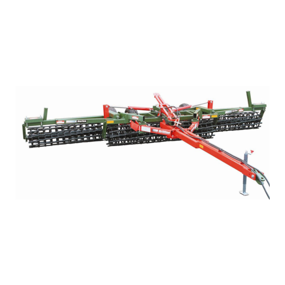
- Page 1 X-Fold Pulverizer Models: X108, X108-1, XC108, XC108-1, XH108, XH108-1, XD108, XD108-1, XO108, and XO108-1 Widths: 19’, 21’, 23’, 25’, and 27’ Operator's Manual LANDOLL CORPORATION 1900 North Street Marysville, Kansas 66508 (785) 562-5381 800-428-5655 ~ WWW.LANDOLL.COM 683rev1113 6J862...
- Page 2 683rev501 6J862...
-
Page 3: Table Of Contents
X108 PULVERIZER CONTENTS Introduction ---------------------------------------------------------------------------------------------------------- 3 Location Reference ----------------------------------------------------------------------------------------- 3 Parts Ordering ----------------------------------------------------------------------------------------------- 3 Safety Suggestions ------------------------------------------------------------------------------------------------ 4 Operating Instructions -------------------------------------------------------------------------------------------- 5 Designed Use ------------------------------------------------------------------------------------------------ 5 Tractor Preparation ----------------------------------------------------------------------------------------- 5 Bleeding Hydraulic Cylinders ---------------------------------------------------------------------------- 5 Field Operation ---------------------------------------------------------------------------------------------- 6 Hitch Adjustment (Used to Limit Soil Pushing) ------------------------------------------------------ 6 Transport ------------------------------------------------------------------------------------------------------ 7 Storing Pulverizer with Drawbar Removed ----------------------------------------------------------- 7 Drawbar Attachment when Pulverizer is Stored ----------------------------------------------------- 7... - Page 4 683rev501 6J862...
-
Page 5: Introduction
INTRODUCTION Your Brillion Pulverizer is built with the best materials and workmanship available. It has been designed to give years of trouble-free operation. Proper care and operation will insure that you receive the service and long life built into this machine. Study this manual carefully before attempting to assemble or operate the machine. -
Page 6: Safety Suggestions
SAFETY SUGGESTIONS Federal law requires you to explain the safety and operating instructions furnished with this machine to all employees before they are allowed to operate the machine. These must be repeated to the em- ployees at the beginning of each season. Be sure to observe and follow the instructions for the safety of anyone operating or near the machine. - Page 7 Safety Signs & Decals There are three levels of hazard intensity that appear with the safety alert symbol on safety decals: DAN- GER, WARNING, and CAUTION. The level of hazard intensity is determined by the following definitions: DANGER - Immediate hazards which WILL result in severe personal injury or death. WARNING - Hazards or unsafe practices which COULD result in severe personal injury or death.
- Page 8 683rev501 6J862 Page 4B...
-
Page 9: Operating Instructions
OPERATING INSTRUCTIONS Designed Use The folding pulverizer is designed to pull behind wide model f eld cultivators and discs. It can be used as an individual unit with the tractor to prepare a seedbed or after seeding to breakdown and pulverizer large sur- face clods. -
Page 10: Field Operation
Field Operation Once the folding pulverizer has been transported to the field, unfold the wings completely. Reversing the hydraulic level should allow the pair of compression springs to push transport lock up with automatic transport lock. After this the implenent may be completely lowered. With manual transport lock reverse the hydraulic lever to allow manual removal of cylinder transport lock. -
Page 11: Transport
Transport (With Automatic Lock Models) Fold the wings for transport. In transport relieve the hydraulic pressure until the cylinder transport lock is tight against pin in the lift arm. There should be no need to do anything with pulverizer when going from field to transport or transport to field. -
Page 12: Maintenance
MAINTENANCE Fasteners After a few hours of use check entire machine and tighten any loose nuts or bolts. Daily or periodic checks should be made thereafter. Tires For Dual Wheel Pulverizers Recommended size of four tires are: 9.5L x 15 6 ply inflated to 24 psi Lubrication Grease zerk fittings daily. -
Page 13: Shipping Bundles
SHIPPING BUNDLES NOTE: REFER TO REPAIR PARTS CATALOG FOR IDENTIFICATION OF PARTS AND FOR APPROXIMATE RELATIONSHIP OF PARTS IN ASSEMBLY. SHIPPING BUNDLE CHECK LIST: Your Brillion Pulverizer is shipped to you in separate assemblies. These shipping bundles and assemblies are: Quantitiy Per Machine Working Width Bundle Name... - Page 14 PULVERIZER WHEEL PLACEMENT 19’ - 27’ Wide Models with 18” Smooth Wheels (A-46) WING A Green Pipe Axle ASSEMBLY: A-46: 5’ = 15 Wheels Must Be Used in the Center “X” Models 6’ = 18 Wheels 7’ = 21 Wheels 8’...
- Page 15 “XD” Models PULVERIZER WHEEL PLACEMENT 19’ - 27’ Wide Models with 20” Ductile Notched Wheels (9J808) WING ASSEMBLY: 5’ = 15 Wheels CENTER SEC- 6’ = 18 Wheels TION 7’ = 21 Wheels (27 Wheels) 8’ = 24 Wheels 9’ = 27 Wheels Position Axle Position Position Axle...
- Page 16 683rev501 6J862 Page 10B...
- Page 17 Tighten all bo1ts to the torques specified in the chart above. It is important that bolts be kept tight at all times. Loose bolts can cause breakage of parts. Check the tightness of bo1ts periodically and keep them tightened to the torques specified above .
- Page 18 Wheel Gang Center Frame End Plate Square Bore Bearing 1/2” x 1 3/4” Figure 4 Capscrew 683rev501 6J862 Page 13 Page12...
- Page 19 683rev501 6J862 Page 13...
- Page 20 Page 14 683rev501 6J862...
- Page 21 683rev501 6J862 Page 15...
- Page 23 683rev501 6J862 Page 16...
- Page 24 683rev501 6J862 rev11-13-07 Page 16A...
- Page 25 683rev501 6J862 Page 17...
- Page 26 LED Warning Lights Red LED Lamp Amber LED Lamp Amber LED Lamp LED Warning Lights Harness Flasher Control Module 7Pin/4Pin WP Harness When plugging in the LED 7-pin connector: 1) Make sure the tractor has a good clean receptacle, free of dirt and corrosion. 2) Make sure the 7-pin connector is inserted ALL the way in.
- Page 27 Warning Lights Placement Dimensions NOTE: When mounting the Red LED Rear Brackets ensure they are placed 50” from Center Line otherwise damage will occur to the lights when the Transport Wheels are raised up. 50" Light Module 25" Bracket 10 1/2" Rear Rear Bracket...
- Page 28 Screw, 1/4-20 x 1-1/2 Red LED Light Module LED Wiring Harness Tie Strap Screw, Module 3/8-16 x 5 Bracket Light Bracket Nut,1/4-20 Nut,3/8-16 Nut,3/8-16 U-Bolt,3/8-16 7 Pin Harness 8” Tywrap Amber Screw, 1/4-20 x 1-1/2 Nut, 1/4-20 U-Bolt, 1/2-13 Washer,1/2 Nut,1/2-13 Lamp Bracket X-PulvElectLayout...
- Page 29 LED Lamp and Harness Installation 1. Install each Light Bracket to the rear frame tube, approximately 25” from the center of the frame, making sure there is sufficient clearance between the bracket and raised tire. Secure with 3/8 Bolt and Nut. Attach the Tail Light Mounts to the ends of the rear frame and secure with 5/8-11 U-Bolts and Nuts, ensure U-Bolts are not interfering with raised wheel arm tube.
-
Page 30: Specifications
683rev501 6J862 Page 18... - Page 31 Field Transport Wheel Ground Clearance: 3 1/2” to 4 1/2” Wings Float: 5 down and 45 Roller Axles: 4 1/2” O.D. steel pipe. Roller Axle Bearings: Self-aligning triple lip sealed. Hydraulics: Single tractor system operates both wing and axle cylinders (included with machine). Two 3 1/2”...
- Page 32 683rev501 6J862 Page 20...
- Page 33 683rev501 6J862 Page 21...
- Page 34 683rev501 6J862 Page 22...
- Page 35 683rev501 6J862 Page 23...
- Page 36 683rev501 Page 24 6J862...
- Page 37 683rev501 Page 25 6J862...
- Page 38 683rev501 6J862...
- Page 40 Equipment from Landoll Corporat ion is built to exacting standards ensured by ISO 9001 registration at all Landoll manufacturing facilities. LANDOLL CORPORATION 1900 North Street Marysville, Kansas 66508 (785) 562-5381 800-428-5655 ~ WWW.LANDOLL.COM Copyright 2013. Landoll Corporation "All rights reserved, including the right to reproduce this material or portions thereof in any form."...
Need help?
Do you have a question about the Brillion X108 and is the answer not in the manual?
Questions and answers