
Related Manuals for Landoll 4620-24


Summary of Contents for Landoll 4620-24
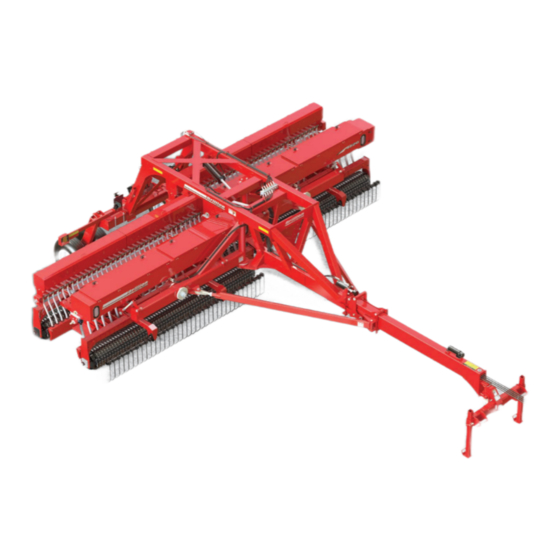
- Page 1 ‘ Folding Seeder Model 4620-24 Operator’s Manual LANDOLL COMPANY, LLC 1900 North Street Marysville, Kansas 66508 (785) 562-5381 800-428-5655 ~ WWW.LANDOLL.COM F-886-0322...
- Page 2 Manuals for 4620-24 Folding Seeder Manual Number Manual Type F-886 Operator’s Manual F-885 Parts Manual...
- Page 3 DANGER DO NOT operate or perform any maintenance tasks on this equipment until you have completed the following: 1. Receive proper training to operate this equipment safely. 2. Read and understand the operator’s manual. 3. Be thoroughly trained on inspection and repair procedures. Failure to comply with this warning may result in serious injury or possibly death.
- Page 5 Table of Contents Safety Information Introduction ........... . 1-1 Description of Unit .
- Page 6 TABLE OF CONTENTS Seed Rate Adjustment ......... . . 3-7 Seed Rate Chart.
- Page 7 TABLE OF CONTENTS Update App..........4-8 Factory Reset .
- Page 8 TABLE OF CONTENTS F-886-0322...
- Page 9 Failure to comply with this warning can result in warranty obligation unless each product is registered personal injury or death, damage to the within 10 days of retail purchase, using the Landoll implement or its components and inferior Company, LLC Ag Products on-line registration process.
- Page 10 TABLE OF CONTENTS SAFETY INFORMATION Safety • When applying decals to the implement, be sure to clean the surface to remove any dirt or residue. Where possible, sign placement should protect the NOTE sign from abrasion, damage, or obstruction from Investigation has shown that nearly 1/3 of all farm mud, dirt, oil etc.
- Page 11 TABLE OF CONTENTS SAFETY INFORMATION Transporting Safety Attaching, Detaching and Storage • Do not stand between the tractor and implement IMPORTANT when attaching or detaching implement unless both It is the responsibility of the owner/operator to are blocked from moving. comply with all state and local laws.
- Page 12 TABLE OF CONTENTS SAFETY INFORMATION Chemical Safety Agricultural chemicals can be dangerous. Improper use can seriously injure persons, animals, plants, soil & property. • Read chemical manufactures instructions and store or dispose of unused chemicals as specified. Handle chemicals with care & avoid inhaling smoke from any type of chemical fire.
- Page 13 TABLE OF CONTENTS SAFETY INFORMATION Decals MEMBER Landoll Company, LLC A LANDOLL PRODUCT Marysville, Kansas www.landoll.com ITEM 7 MODEL # 170509 SERIAL # MADE IN USA 1-573-010006 ITEM 2 - PLACARD FARM EQUIPMENT ITEM 10 MANUFACTURERS 203668 A S S O C I A T I O N...
- Page 14 TABLE OF CONTENTS SAFETY INFORMATION Figure 1-3: Decal Locations (1 of 3) F-886-0322...
- Page 15 TABLE OF CONTENTS SAFETY INFORMATION Figure 1-4: Decal Locations (2 of 3) F-886-0322...
- Page 16 TABLE OF CONTENTS SAFETY INFORMATION Figure 1-5: Decal Locations (3 of 3) F-886-0322...
- Page 17 Chapter 2 TABLE OF CONTENTS Assembly The 4620-24 Folding Seeder Frame comes assembled. CAUTION Attach a Seeder Undercarriage Assembly to each Wing Arm and connect the Wing Lock Hydraulic Circuit. Install Do not work on or under this machine unless...
- Page 18 Folding Seeder Frame Wing Arms to ensure that the circuits are functioning properly. Do not attempt to lift heavy parts manually. Use a 4620-24 hydraulic system consists of 3 separate circuits. hoist or a fork lift to move these parts into position. Lift Circuit – Blue •...
- Page 19 TABLE OF CONTENTS ASSEMBLY Seeder Undercarriage Assembly RH Wing Arm Folding Seeder Frame LH Wing Arm Seeder Undercarriage Assembly Figure 2-2: Wing Arm Assembly, Top View Locknut,3/4-10 Bolt, 3/4-10 x 2-1/2 Pin, Threaded w/Retainer Locknut,3/4-10 Spindle Carrier Washer,Flat,3/8 Tie Rod Nylon,Thrust Nylon,Thrust Bolt,...
- Page 20 TABLE OF CONTENTS ASSEMBLY Brillion Elite Mini Monitor Sensors to the Seeder Harness. See Figure 2-4. IMPORTANT Shroud Pin ID Terminal White Wire The Brillion Elite Mini Monitor System by Loup utilizes a MUX communication line. Sensors must be learned into the Monitor. Location of each pre-learned Smart Shaft Sensor or Bin Level Sensor is important Black Wire for proper Monitor display.
- Page 21 TABLE OF CONTENTS ASSEMBLY Brillion Elite Mini Monitor - Single Seed Box Sensor Schematic Figure 2-5: Brillion Elite Mini Monitor - Single Seed Box Sensor Schematic F-886-0322...
- Page 22 TABLE OF CONTENTS ASSEMBLY Brillion Elite Mini Monitor - Seed Shaft Sensor Washer, Locknut,Flange Flat #8 #8-32 Sensor Mount Seed Shaft, 3/8 Sq Smart Screw,Rnd Hd #8-32 x 1-1/4 Shaft Sensor Spacer w/Magnet Sensor Mount Spacer SECTION A-A w/Magnet Seed Shaft, Smart 3/8 Sq Shaft Sensor...
- Page 23 TABLE OF CONTENTS ASSEMBLY Brillion Elite Mini Monitor - Bin Level Sensor Locknut,Flange #8-32 Bin Level Sensor Cord Grip Compression Nut Cord Grip Includes Locknut Cord Grip Locknut Bin Level Terminals Sensor Bracket 3-Pin Shroud Bin Level Sensor Cord Grip Compression Nut Locknut,Flange #8-32...
- Page 24 TABLE OF CONTENTS ASSEMBLY Brillion Elite Mini Monitor - Ground Speed Sensor Clutch Connector Bolt,Carriage 5/16-18 x 1 Actuator Assembly Includes Set-Screw Washer,Flat #8 Screw,Rnd Hd Set Screw #8-32 x 1-1/4 Locknut,Flange #8-32 Clutch Shaft Smart Shaft Bracket, Sensor Pickup Switch Clutch Connector Actuator Assembly...
- Page 25 TABLE OF CONTENTS ASSEMBLY Table provided for general use. NOTES: F-886-0322...
- Page 26 Washer,Flat 1/4 3-Pin Amp Bolt,1/4-20 X 1 Power Cable Convenience Outlet Bolt,1/2-13 X 1-1/2 Straight Bracket 9-Pin Amp Sensing/Clutch 4620-24 Monitor Control Connector Washer,Flat 1/4 Nut,Lock 1/4-20 Angle Bracket Nut,Flange Ny-Lok,1/2-13 Console Figure 2-9: Console w/Clutch Control Tractor Installation 2-10...
- Page 27 TABLE OF CONTENTS ASSEMBLY Figure 2-10: Console w/Clutch Control Schematic F-886-0322 2-11...
- Page 28 Figure 2-11: Tool Storage LED Warning Lamps Installation Plug Holder For shipping, the 4620-24 Folding Seeder has the left and right hand Lamp Brackets removed to reduce transport width. 1. Attach the Left and Right Lamp Brackets with 5/8-11 U-Bolts and Locknuts. See Figure 2-13.
- Page 29 TABLE OF CONTENTS ASSEMBLY Flat Washer,1/4-20 Bolt,1/4-20 x 1-1/2 Locknut,1/4-20 Amber Lamp LH Lamp Bracket Locknut, 5/8-11 Amber Connector Warning Lamp Harness RH Lamp Bracket Connector U-Bolt,5/8-11 4620-24 OpElectrical Figure 2-13: LED Warning Lamps Installation F-886-0322 2-13...
- Page 30 U-Bolt,5/8-11 Harrow Mount Bolt, 3/8-16 x 1-1/4 Locknut, Flange 5/8-11 Locknut, Locknut,3/8-16 3/8-16 Harrow Assembly 203791 Locknut, 3/8-16 Bolt, 3/8-16 x 1-1/4 Harrow Assembly 4620-24 TrackRemo Bolt, 203794 3/8-16 x 1-1/4 Locknut, 3/8-16 Figure 2-14: Coil Tine Harrow 2-14 F-886-0322...
- Page 31 DANGER DANGER DANGER DANGER Never allow anyone to ride on the 4620-24 Folding Always lock the Tractor Drawbar in the center Seeder at any time. Allowing a person to ride on position when transporting the unit. Failure to do the machine can inflict serious personal injury or so can result in serious injury or death and cause death to that person.
- Page 32 TABLE OF CONTENTS OPERATION Tractor Preparation Attaching Folding Seeder to the Tractor The 4620-24 Folding Seeder is designed to be pulled by a Semi-Mounted Two Point Hitch. DANGER DANGER Before attaching the Seeder Hitch, prepare the tractor as follows: Do not allow any bystanders to stand between the 1.
- Page 33 TABLE OF CONTENTS OPERATION Detaching the Folding Hydraulic System Seeder from Tractor WARNING When unhitching the Folding Seeder from the tractor, park the seeder on a level area to prevent rolling and Escaping hydraulic fluid can cause serious shifting. personal injury. Relieve system pressure before repairing, adjusting, or disconnecting.
- Page 34 Hydraulic Lift System UnFolding: 1. Fully raise the Seeder to relieve pressure off the The 4620-24 Folding Seeder is equipped with a Transport Locks. Remove Transport Locks and Hydraulic Lift System to raise and lower the unit from relocate to storage position. See Figures 3-7 and 3-8.
- Page 35 TABLE OF CONTENTS OPERATION Pivot Lock Link Tie Rod Wing Assembly Pivot Lock Plate Spindle Carrier Seeder Undercarriage Pin,Threaded Assembly w/Retainer Hyd Cylinder 2 x 3 Figure 3-5: Pivot Lock Disengaged Pivot Lock Link Wing Assembly Tie Rod Pivot Lock Spindle Carrier Plate Pin,Threaded...
- Page 36 1. To install the Transport Locks, fully raise the machine. Remove the Transport Lock from the storage position and install it over the Hydraulic Cylinder Rod. See Figures 3-7 and 3-8. Transport Lock Hydraulic Cylinder Hair Pin Bent Pin 4620-24 OpTransportLockStored Figure 3-7: Transport Lock Storage Location F-886-0322...
- Page 37 TABLE OF CONTENTS OPERATION Seed Rate Adjustment IMPORTANT The clutch must be disengaged (power off) when WARNING seed shafts are turned manually for calibration. The seed rate chart is located inside the seed box cover • To prevent damage to the seed meters, do not and in this manual.
- Page 38 RATES ARE INTENDED AS A GUIDE ONLY. VARIATIONS IN SIZE AND CLEANLINESS WILL AFFECT RATES. CHECK ACREAGE AND POUNDS OF SEED USED FOR BEST RESULTS. * WILL CRACK SOME SEEDS AT THESE SETTINGS NOT RECOMMENDED: LENTILS, SORGHUM, SUDAN GRASS Figure 3-11: 4620-24 Seed Rate Chart F-886-0322...
- Page 39 Shaft 163 revolutions Counter-Clockwise (CCW) with Landoll assumes no liability pertaining to seeding rates provided Crank, 41 turns may be used if results are achieved with this seeder. Rates listed are general in adjusted as stated in Step 5.
- Page 40 TABLE OF CONTENTS OPERATION Clutch Operation The Clutch is controlled by the Brillion Elite Mini Monitor. Clutch characteristics are as follows: 1. The Clutch is engaged when power (12 volts) is applied. 2. The Seeder has provisions to mechanically lock the Clutch to drive the Seed Metering System, by aligning the hole in the Clutch Shaft with the slot in the Clutch Hub and securing with a 1/4 x 1-3/4 Bolt, Flat...
- Page 41 TABLE OF CONTENTS OPERATION Brillion Elite Mini Monitor • The Elite Mini Tractor Harness attaches to the Brillion Elite Mini Monitor and connects the Seeder Main Brillion Elite Mini Monitor provides information to the Harness. See Figure 2-5. The 6-Pin Connection may operator and acts as an interface for clutch control.
- Page 42 TABLE OF CONTENTS OPERATION Coil Tine Harrow The Seeder has a Standard Coil Tine Harrow to remove tire tracks before the rollers compact the soil. The coils are individually mounted for flexibility and backup protection. The Tines depth should be adjusted so the tips are approximately 2"...
- Page 43 TABLE OF CONTENTS OPERATION Transporting the Folding g. Fold the Folding Seeder. Fully raise the Seeder Rockshaft and 3-PT Hitch. Seeder h. Make sure all transport locks and pins are installed. Do not depend solely on the implement 1. Check and follow all federal, state, and local hydraulics for transport.
- Page 44 TABLE OF CONTENTS OPERATION Table provided for general use. NOTES: 3-14 F-886-0322...
- Page 45 Chapter 4 TABLE OF CONTENTS Brillion Elite Mini Monitor Overview • Field Acres and Total Acres • Clutch Control The Brillion Elite Mini Monitor is a full featured display • (Up to 6) Six Seed Shaft Rotation Sensors designed to provide accurate information to the operator •...
- Page 46 TABLE OF CONTENTS BRILLION ELITE MINI MONITOR 9:30AM SETTINGS BACK APP VER: 2.1.1 SPEED CLUTCH SCROLL UP SETTINGS SETTINGS INSTALL SHAFT SETUP SETTINGS DIAGNOSTICS SETTINGS DISPLAY SCROLL DOWN SETTINGS Figure 4-2: Settings Menu Display (4620) Settings Menu - Source: Shaft Sensor Speed SHAFT SHAFT SPEED...
- Page 47 TABLE OF CONTENTS BRILLION ELITE MINI MONITOR Speed Source Displays Speed Source Icon Features Pulses Per Revolution SPEED SETTINGS BACK Pulses Per Revolution are the PULSES PER IMP. SWITCH: SOURCE: number of magnets the implement REV: SHAFT SPEED DISABLED mounted speed sensor sees in one revolution of the shaft being monitored.
- Page 48 Clutch Setting SETTINGS BACK EXIT & SAVE The 4620-24 Folding Seeder has a Clutch on each NOTE Seeder Unit that will be controlled by the Brillion Elite Mini Monitor. Each Clutch must be set. During the calibration the monitor is looking for the number of pulses produced from the seeder mounted sensor or in the case of radar, the number of radar pulses.
- Page 49 TABLE OF CONTENTS BRILLION ELITE MINI MONITOR Settings Menu - Remove A Sensor INSTALL Install Setup Select this option to remove a SETUP REMOVE A sensor from your existing system. RECEIVER SENSOR Select “Install Setup” icon to Learn New System, Add A Sensor, or Remove A Sensor to your machine.
- Page 50 The Diagnostics screen can help in identifying issues with Seed Shaft Settings sensors, harnessing or other items. Status reports for 4620-24 Folding Seeder can have up to six Smart Shaft Battery Voltage, Sensors Learned, MUX Communication Sensors that indicate shaft rotation. Each Smart Shaft speed and GPS Communication speed are displayed.
- Page 51 TABLE OF CONTENTS BRILLION ELITE MINI MONITOR Settings Menu - Settings Menu - DISPLAY GPS Settings Display Settings RECEIVER SETTINGS SETTINGS “GPS Settings” defines any Baudrate, Speed Corrections or the current GPS Status. DISPLAY SETTINGS BACK UNITS GPS SETTINGS BACK VOLUME BRIGHTNESS GPS BAUDRATE...
- Page 52 TABLE OF CONTENTS BRILLION ELITE MINI MONITOR Service And Technical System Update Support The system update screen is used SYSTEM to update to newer versions of UPDATE Contact: Loup Electronics Inc. software or reset to factory default Address: 2960 N. 38th Street settings.
- Page 53 Chapter 5 TABLE OF CONTENTS Maintenance General Torque Specifications (rev. 4/97) This chart provides tightening torques for general purpose applications when special torques are not specified on process or drawing. Assembly torques apply to plated nuts and capscrews assembled without supplemental lubrication (as received condition).
- Page 54 TABLE OF CONTENTS MAINTENANCE Hydraulic Fitting Torque Specifications 37 degree JIC, ORS, &ORB (REV. 10/97 This chart provides tightening torques for general purpose applications when special torques are not specified on process or drawing. Assembly torques apply to plated nuts and capscrews assembled without supplemental lubrication (as received condition).
- Page 55 MAINTENANCE Tires Lubrication Maintenance Recommended Tire Size: 12.5L x 15 FI The 4620-24 Folding Seeder is equipped with maintenance free bearings in the lifts and wing Tire Inflation Pressure: 52PSI assemblies. These areas require no lubrication. When Re-Installing the 5/8-18 Wheel Nuts tighten to 50 Roller assembly bearings are sealed with a triple lip seal foot-pounds using the sequence in See Figure 5-1.
- Page 56 TABLE OF CONTENTS MAINTENANCE Hydraulic Maintenance Hose Identification 1. The hydraulic hoses are color coded to help identify IMPORTANT and match the attaching hoses on the Seeder. An Unfold, lower the unit to the ground, and relieve hydraulic identification decal is placed on the front of the hitch pressure before attempting to service any hydraulic to help identify the hoses.
- Page 57 TABLE OF CONTENTS MAINTENANCE Roller Clamp Tightening Servicing Seed Shaft Assembly Tighten the Clamp Socket Head Bolt. Torque to 75ft/lbs. Thereafter check assemblies every 50-100 hours. See Figure 5-5. Clamps must be assembled with the open IMPORTANT section straddling the welded seam of the drum pipe. The clutch must be disengaged (power off) when Seed Shafts are turned manually.
- Page 58 TABLE OF CONTENTS MAINTENANCE Seed Meter Adjustment IMPORTANT All the Seed Meters MUST BE CLOSED! It may be necessary to individually adjust Seed Meter Adapter with Seed Meter attached or Seed Meter if Meter Adapter is not used. A Section All Seed Meters must be set the same to ensure seeding with No Gaps uniformity.
- Page 59 TABLE OF CONTENTS MAINTENANCE LED Warning Lamps Storage When plugging in the LED 7-Pin Warning Lamp 1. The service life of the Folding Seeder will be extended Connector: by proper off-season storage practices. Prior to storing the unit, complete the following procedures: 1.
- Page 60 TABLE OF CONTENTS MAINTENANCE Table provided for general use. NOTES: F-886-0322...
- Page 61 Chapter 6 TABLE OF CONTENTS General Reference and Specifications Product Attributes SS 24 Description 24 ft. (7.3 m) Agricultural Seeder Approximate Weight (Empty) 16,178 lbs. (7,338 kg) Working Width 24 ft. (7.3 m) Transport Width 13 ft. 9 in. (4.2 m) Overall Length (Transport) 31 ft.
- Page 62 TABLE OF CONTENTS GENERAL REFERENCE AND SPECIFICATIONS Table provided for general use. NOTES: F-886-0322...
- Page 63 Document Control Revision Log: Date Form # Improvement(s): Description and Comments 05/2019 F-886-0519 New Release 03/2022 F-886-0322 ECN 46900, 47187, 47696, 47707 - Add Brillion Elite Mini Monitor by Loup ECN 47474 - Add QR Code Decals Add High Powered Magnet Warning Add Brillion Elite Mini Monitor Manual Chapter...
- Page 64 Equipment from Landoll Company, LLC is built to exacting standards ensured by ISO 9001 registration at all Landoll manufacturing facilities. Folding Seeder Model 4620-24 Operator’s Manual Re-Order Part Number F-886 LANDOLL COMPANY, LLC 1900 North Street Marysville, Kansas 66508 (785) 562-5381 800-428-5655 ~ WWW.LANDOLL.COM...
Need help?
Do you have a question about the 4620-24 and is the answer not in the manual?
Questions and answers