Table of Contents
Advertisement
Advertisement
Table of Contents

Related Manuals for EDAN iM8 Series


Summary of Contents for EDAN iM8 Series
- Page 2 About this Manual P/N: 01.54.456009-10 Release Date: April 2013 Statement This manual will help you understand the operation and maintenance of the product better. It is reminded that the product shall be used strictly complying with this manual. User’s operation failing to comply with this manual may result in malfunction or accident for which the manufacturer cannot be held liable.
- Page 3 Terms Used in this Manual This guide is designed to give key concepts on safety precautions. WARNING A WARNING label advises against certain actions or situations that could result in personal injury or death. CAUTION A CAUTION label advises against actions or situations that could damage equipment, produce inaccurate data, or invalidate a procedure.
-
Page 4: Table Of Contents
Table of Contents Chapter 1 Intended Use and Safety Guidance ................1 1.1 Intended Use...........................1 1.2 Safety Guidance ........................1 1.2.1 Environment........................1 1.2.2 Power Source Requirements ..................1 1.2.3 Grounding the Monitor ....................1 1.2.4 Equipotential Grounding.....................2 1.2.5 Condensation.......................2 1.2.6 Safety Precautions.......................2 1.2.7 Explanation of Symbols on the Monitor ..............5 Chapter 2 Installation of Monitor ....................7 2.1 Opening the Package and Checking..................7 2.2 Connecting the Power Cable....................7... - Page 5 4.4 Face Select ...........................26 4.5 Time Setup ...........................27 4.6 Record Setup ........................28 4.7 Module Setup ........................29 4.8 Tracing Waveforms Selection ....................29 4.9 Monitor Version ........................30 4.10 Alarm Volume ........................30 4.11 Key Volume ........................31 4.12 Drug Calculation ........................31 4.13 Waveform Demonstration ....................32 4.14 Maintenance ........................32 4.15 Data Storing ........................34 Chapter 5 Face Select........................39...
- Page 6 Chapter 8 Recording (Optional) .....................56 8.1 General Information on Recording ..................56 8.2 Recording Type ........................56 8.3 Recording Startup.........................58 8.4 Recorder Operations and Status Messages ................59 Chapter 9 Trend and Event ......................61 9.1 Trend Graph .........................61 9.2 Trend Table...........................62 9.3 NIBP Recall..........................64 9.4 Alarm Event Recall ......................65 Chapter 10 Drug Calculation and Titration Table (Optional) .............68 10.1 Drug Calculation ........................68...
- Page 7 12.9.3 Installing Electrode for RESP Measurement ............97 12.9.4 RESP SETUP ......................98 12.9.5 RESP Alarm Message ...................100 12.10 Maintenance and Cleaning.....................101 Chapter 13 SpO Monitoring ......................102 13.1 What is SpO Monitoring....................102 13.2 Precautions during SpO /Pulse Monitoring ..............103 13.3 Monitoring Procedure ......................103 13.4 SpO SETUP ........................104 13.5 Alarm Description ......................106...
- Page 8 17.1 General ..........................134 17.2 Monitoring Procedure ......................135 17.3 CO SETUP........................140 17.4 Alarm Information and Prompt ..................143 17.5 Maintenance and Cleaning....................144 Chapter 18 Accessories and Ordering Information ..............145 Chapter 19 Warranty and Service....................149 19.1 Warranty ...........................149 19.2 Contact Information ......................149 Appendix I Specifications ......................150 A1.1 Classification........................150 A1.2 Specifications ........................150 A1.2.1 Size and Weight....................150...
- Page 9 A3.3 ECG Default Settings ......................168 A3.4 RESP ..........................170 A3.5 SpO ..........................170 A3.6 PR ............................170 A3.7 NIBP..........................171 A3.8 TEMP ..........................171 A3.9 IBP...........................172 A3.10 CO ..........................172...
-
Page 10: Chapter 1 Intended Use And Safety Guidance
Patient Monitor User Manual Intended Use and Safety Guidance Chapter 1 Intended Use and Safety Guidance 1.1 Intended Use This monitor is intended to be used for monitoring, storing, reviewing, recording, and generating alarms for multiple physiological parameters including ECG, respiration (RESP), temperature (TEMP), oxygen saturation of arterial blood (SpO ), non-invasive blood pressure (NIBP), invasive blood pressure (IBP) and carbon dioxide (CO... -
Page 11: Equipotential Grounding
Patient Monitor User Manual Intended Use and Safety Guidance 1.2.4 Equipotential Grounding Protection class 1 instruments are already included in the protective grounding (protective earth) system of the room by way of grounding contacts in the power plug. For internal examinations on the heart or the brain, the monitor must have a separate connection to the equipotential grounding system. - Page 12 Patient Monitor User Manual Intended Use and Safety Guidance WARNING Accessory equipments connected to the analog and digital interfaces must be certified according to the respective IEC/EN standards (e.g. IEC/EN 60950 for data processing equipment and IEC/EN 60601-1 for medical equipment). Furthermore all configurations shall comply with the valid version of the standard IEC/EN 60601-1-1.
- Page 13 Patient Monitor User Manual Intended Use and Safety Guidance CAUTION Federal (U.S.) laws restrict this device to sale, distribution and use by, or on the order of a physician. Electromagnetic Interference -Ensure that the environment in which the patient monitor is installed is not subject to any sources of strong electromagnetic interference, such as radio transmitters, mobile telephones, etc.
-
Page 14: Explanation Of Symbols On The Monitor
Patient Monitor User Manual Intended Use and Safety Guidance 1.2.7 Explanation of Symbols on the Monitor This symbol indicates that the equipment is IEC/EN60601-1 Type CF equipment. The unit displaying this symbol contains an F-Type isolated (floating) patient applied part providing a high degree of protection against shock, and is suitable for use during defibrillation. - Page 15 Patient Monitor User Manual Intended Use and Safety Guidance Date of manufacture Manufacturer Part Number Recycle The symbol indicates that the device should be sent to the special agencies according to local regulations for separate collection after its useful life. Federal (U.S.) law restricts this device to sale by or on the order of Rx only a physician.
-
Page 16: Chapter 2 Installation Of Monitor
Patient Monitor User Manual Installation of Monitor Chapter 2 Installation of Monitor Installation should be carried out by qualified service personnel, either by the hospital’s biomedical department, or by the manufacturer’s Support. For mechanical and electrical installation, you need technically qualified personnel with knowledge of English. -
Page 17: Powering On The Monitor
Patient Monitor User Manual Installation of Monitor 2.3 Powering on the Monitor After you power on the monitor, LOGO information will be displayed on the screen. WARNING If any sign of damage is detected, or the monitor displays some error messages, do not use it on any patient. -
Page 18: Chapter 3 Introduction
Patient Monitor User Manual Introduction Chapter 3 Introduction This user manual is based on the maximum configuration and therefore your monitor may not have all of the functions and options described in the manual. Also, illustrations in this manual serve as examples only and do not necessarily reflect the setup on your monitor. The content displayed on you monitor depends on the way it has been tailored for your hospital. - Page 19 Patient Monitor User Manual Introduction The monitor has 3 models: iM8, iM8A and iM8B. Product Shell figure / Size (L×W×H) Functions models Screen size Host: Square / ECG/RESP, SpO NIBP, TEMP, IBP, CO 319mm×154mm×267.8mm 12.1-inch Host: Square / ECG/RESP, SpO NIBP, TEMP, iM8A IBP, CO...
- Page 20 Patient Monitor User Manual Introduction Figure 3-3 iM8A Patient Monitor Figure 3-4 iM8B Patient Monitor - 11 -...
-
Page 21: Screen Display
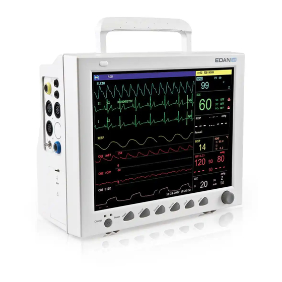
Patient Monitor User Manual Introduction The monitor can monitor the following parameters and waveforms: ECG: Heart Rate (HR) Maximum 7-channel Arrhythmia and ST-segment analysis (optional) RESP: Respiration Rate (RR) Respiration Waveform Oxygen Saturation (SpO ), Pulse Rate (PR) Plethysmogram NIBP: Systolic Pressure (SYS), Diastolic Pressure (DIA), Mean Pressure (MAP), PR (NIBP) TEMP: Channel-1 Temperature (T1), Channel-2 Temperature (T2), Temperature Difference between two channels (TD) - Page 22 Patient Monitor User Manual Introduction ① ③ ② ④ Figure 3-5 Main Display Information Area(① ④) The Information Area is at the top and bottom of the screen, displaying the operating state of the monitor and the status of the patient. The information area contains the following data: Bed number of the monitored patient Type of patient.
- Page 23 Patient Monitor User Manual Introduction operating time and maintenance requirements; means there is no battery equipped in the monitor. Indicates the audio alarm is turned off. Indicates the audio alarm is paused. Displays beside a parameter to indicate the alarm is turned off. USB storage indicator Select this item to enter Standby mode, the dialog pops up: STANDBY...
- Page 24 Patient Monitor User Manual Introduction to the actual requirement. Its range is described in the part: IBP Monitoring. In the IBP waveform area, the waveform scale is displayed. The three dotted lines for each IBP waveform from up to down represent respectively the upper limit scale, reference scale and lower limit scale. The values of these three scales can be set.
-
Page 25: Button Functions
Patient Monitor User Manual Introduction Charge Indicator and Charge Status To indicate the status of charging: When the battery is charged, the light color turns to orange. 3.3 Button Functions All the operations to the monitor can be finished by several buttons and a knob. They are: Figure 3-7 Buttons Press to call up the SYSTEM MENU. - Page 26 Patient Monitor User Manual Introduction In normal mode, press this button to freeze all the waveforms on the ⑤ Freeze screen. In FREEZE mode, press this button to restore the waveform refreshing. Press this button to return to the main interface. ⑥...
-
Page 27: Interfaces
Patient Monitor User Manual Introduction 3.4 Interfaces For the convenience of operator, interfaces of different functions are in different sites of the monitor. There is a USB port on the panel for connecting USB storage. Right Side of the Monitor At the right side of the monitor, there are a bracket of water trap for CO module (①) and the recorder’s paper inlet cover (②). - Page 28 Patient Monitor User Manual Introduction Figure 3-9 Left Panel Rear Panel ① ⑤ ② ③ ⑥ ④ Figure 3-10 Rear Panel of iM8, iM8A and iM8B ① Network Interface (reserved): Standard RJ45 Socket, for connecting to MFM-CMS of the manufacturer ②...
-
Page 29: Built-In Rechargeable Battery
Patient Monitor User Manual Introduction 3.5 Built-in Rechargeable Battery 3.5.1 Battery Safety Information WARNING Before using the rechargeable lithium-ion battery (hereinafter called battery), be sure to read the user manual and safety precautions thoroughly. Do not place battery in the monitor with the (+) and (-) in the wrong way around. Do not connect the positive (+) and negative (-) terminals with metal objects, and do not put the battery together with metal object, which can result in short circuit. -
Page 30: Checking Battery Performance
Patient Monitor User Manual Introduction Figure 3-11 Battery Compartment 3.5.3 Checking Battery Performance The performance of rechargeable batteries may deteriorate over time. Battery maintenance as recommended here can help to slow down this process. 1. Disconnect the patient from the monitor and stop all monitoring and measurement. 2. -
Page 31: Chapter 4 System Menu
Patient Monitor User Manual System Menu Chapter 4 System Menu The SYSTEM MENU is introduced in this chapter. The monitor features in flexible configurations. You can configure various aspects of the monitor, including the parameters to be monitored, sweeping speed of the waveforms, audio signal volume, and output content. -
Page 32: Patient Setup
Patient Monitor User Manual System Menu 4.1 Patient Setup Pick PATIENT SETUP in SYSTEM MENU to call up the following menu. Figure 4-3 Patient Setup You can set up the following patient information: Department in which the patient receives treatment. DEPT. -
Page 33: Default Setup
Patient Monitor User Manual System Menu Patient blood type (Pick A, B, O, AB, or N. N represents unknown BLOOD blood type) Admission of new patient NEW PATIENT Also in this menu, the user may select “NEW PATIENT” item to access “CONFIRM TO UPDATE PATIENT”... -
Page 34: Mark Event
Patient Monitor User Manual System Menu Figure 4-5 Default Menu In this sub-menu, you can select the factory default or the user-defined default. Also in this sub-menu, you can save the current configuration as the user-defined default configuration. At this time, the system will automatically save all the setups in the parameter menu, ECG lead, gain and filter way as the user-defined default configuration according to the patient type. -
Page 35: Face Select
Patient Monitor User Manual System Menu Figure 4-7 Mark Event To mark the event: Use the trim knob to select one from event A, B, C and D. There is a “@” signal for the one selected. To cancel your selection, repress the knob at selected item. Press EXIT to return to the previous menu. -
Page 36: Time Setup
Patient Monitor User Manual System Menu After entering LARGE FONT FACE SCREEN, you can select three modes. See as follows: Figure 4-9 Large Font Face Select 4.5 Time Setup Select TIME SETUP item in SYSTEM SETUP menu to access the sub-menu of TIME SETUP as shown below. -
Page 37: Record Setup
Patient Monitor User Manual System Menu 4.6 Record Setup Select RECORD in SYSTEM SETUP menu to call up the following menu: Figure 4-11 Record In the sub-menu, the user may select the REC WAVE1, REC WAVE2 or REC WAVE3, a maximum of 3 waveforms can be printed out. -
Page 38: Module Setup
Patient Monitor User Manual System Menu Display CO module waveform. (If there is no CO waveform on the screen, we cannot choose it. But in full screen multi-lead mode, we can choose it though we can not see it.) No display for this channel. RT REC TIME: represents “real-time recording time”, for which two selections are available: CONTINUAL and 8S (8 seconds). -
Page 39: Monitor Version
Patient Monitor User Manual System Menu Figure 4-12 Trace Setup You can define the traces displayed on the screen in this menu. The waveforms available for selection are those whose modules have been selected in MODULE SETUP menu. 4.9 Monitor Version Pick VERSION to show the software version information of this monitor. -
Page 40: Key Volume
Patient Monitor User Manual System Menu Figure 4-13 Alarm Setup - ALARM VOL: set the alarm volume by turning the knob. The valid range is from 1 to 10. - ALM REC TIME: set to 8s, 16s or 32s. You can also set alarm parameters in MAITAIN > USER MAINTAIN > ALARM SETUP. Refer to Chapter6 Alarm for details. -
Page 41: Waveform Demonstration
Patient Monitor User Manual System Menu 4.13 Waveform Demonstration Select DEMO item in SYSTEM MENU to call up INPUT DEMO KEY. After entering the password, the system enters the Demonstration Waveform status. The purpose of waveform demonstration is only to demonstrate the machine performance and for training purposes. - Page 42 Patient Monitor User Manual System Menu LOCAL NET NO: Physical Number of monitor. ALARM SETUP>>: You can set up parameters of alarm. For more details refer to Chapter6 Alarm. Figure 4-16 Alarm Setup OTHER SETUP >>: You can set some other functions. See as follows: Figure 4-17 Other Setup NURSE CALL: Turn on or off the nurse call.
-
Page 43: Data Storing
Patient Monitor User Manual System Menu colours can be selected. Selecting DEFAULT can set the colour configuration to default setup. Figure 4-18 Colour select menu Factory Maintain Factory maintenance function is only available for the service engineers of the manufacturer or representatives authorized by the manufacturer. - Page 44 Patient Monitor User Manual System Menu patient ID has not been set, the data will be stored into the default folder “patient” in USB storage. Each data file is named by time, it can save 96-hour trend data with 1-min resolution, 1-hour trend data with 1-second resolution, 60 groups parameter alarm, 60 groups ARR data, 500 groups NIBP data, 720 seconds waveforms and patient information.
- Page 45 Patient Monitor User Manual System Menu Select patient ID to enter the following dialog box for selecting the data: Figure 4-22 Select data After selecting the time, the data will be imported from the USB storage to the monitor, it indicates as follows: Figure 4-23 Importing data -...
- Page 46 Patient Monitor User Manual System Menu - DELETE ID: users can delete all the data for current ID by this item. The dialog box displays: Figure 4-24 Confirm to delete After deleting successfully, it indicates DELETE SUCCESS! NOTE: The data of the current monitoring patient ID can not be deleted. If the data has not been saved successfully because of the power supply off or USB storage off, when the users queries data by SELECT DATA, the prompt pops up: Figure 4-25 Invalid data!!!
- Page 47 Patient Monitor User Manual System Menu Figure 4-26 Please choose data If the USB storage is full, it indicates NO SPACE IN USB STORAGE on the screen. NOTE: Data store function can be set to on or off in FACTORY MAINTAIN by the manufacturer or the representative permitted by the manufacturer.
-
Page 48: Chapter 5 Face Select
Patient Monitor User Manual Face Select Chapter 5 Face Select This monitor has four different operating screens, which are Standard Screen, Trend Screen, oxyCRG Screen and Large Font Screen. Users can select different operating screens for necessary information as requested. 5.1 Selecting Operating Screen In the SYSTEM MENU, select the FACE SELECT option in the SYSTEM SETUP menu to call up the dialog box as shown in the figure below. -
Page 49: Oxycrg Screen
Patient Monitor User Manual Face Select Select trend parameter If multiple parameters are located at the same position on the trend graph, by selecting the corresponding hot key of a parameter on the trend graph, you can have the trend graph of this parameter displayed on the screen. - Page 50 Patient Monitor User Manual Face Select Figure 5-2 Large Font Face Select Three display modes 1. ECG+SpO +NIBP display mode: Figure 5-3 ECG+SpO +NIBP display mode - 41 -...
- Page 51 Patient Monitor User Manual Face Select 2. SpO +NIBP display mode: Figure 5-4 SpO +NIBP display mode - 42 -...
- Page 52 Patient Monitor User Manual Face Select 3. SpO display mode: Figure 5-5 SpO display mode Exit Large Font Screen In the LARGE FONT FACE SELECT menu, choose EXIT to return to FACE SELECT screen. - 43 -...
-
Page 53: Chapter 6 Alarm
Patient Monitor User Manual Alarm Chapter 6 Alarm This chapter gives general information about the alarm and measures to be taken accordingly. Alarm setup and prompt messages are provided in respective parameter setup sections. WARNING A potential hazard can exist if different alarm presets are used for the same or similar equipment in any single area, e.g. - Page 54 Patient Monitor User Manual Alarm NOTE: The Physiological Alarm area is on the upper right part of the screen. The Technical Alarm area is on the left side of the Physiological Alarm area. If the monitor is connected to the external alarm prompt system (e.g. the alarm speaker and indicator are connected onto the rear panel of the monitor), when alarm condition is active, the external alarm prompt system responds in the same way as the monitor.
- Page 55 Patient Monitor User Manual Alarm Alarm Sound The high/medium/low-level alarms are indicated by the system in following different audio ways: Alarm level Audio prompt Mode is “DO-DO-DO------DO-DO, DO-DO-DO------DO-DO”, which High is triggered once every 10 seconds. Medium Mode is “DO-DO-DO”, which is triggered once every 25 seconds. Mode is “DO-”, which is triggered once every 30 seconds.
-
Page 56: Alarm Setup
Patient Monitor User Manual Alarm 6.1.3 Alarm Setup Setup alarm in the ALARM SETUP menu Press the ALARM SETUP button in the SYSTEM SETUP menu to call up ALARM SETUP menu (default menu) as shown below. In the ALM SEL item, the user may set up the information about common alarm setup and the alarm setup of each parameter. - Page 57 Patient Monitor User Manual Alarm MAINTAIN > ALARM SETUP. See as follows: Figure 6-2 Alarm Setup in User Maintain ALM SILENCE TIME: Set up the duration of Alarm Pause status, it can be set to 1 minute, 2 minutes and 3 minutes. ALARM SILENCE: When it set to ON, hold the Silence button on the front panel for 3 seconds, and the alarm system will be silenced.
-
Page 58: Alarm Cause
Patient Monitor User Manual Alarm When it is set to UNLATCH, when alarm occurs, the monitor will give an audio prompt and a light prompt (the FONT FLASH and BK FLASH are not active). Different from the LATCH mode, after this alarm event is over, the monitor will stop giving the alarm prompt. 6.2 Alarm Cause An alarm occurs when: 1. -
Page 59: Parameter Alarm
Patient Monitor User Manual Alarm 6.4 Parameter Alarm WARNING Prior to monitoring, make sure that the alarm limit settings are appropriate for your patient. Setting alarm limits to extreme values may cause the alarm system to become ineffective. The setup for parameter alarms is in their menus. In the menu of a specific parameter, you can check and set the alarm limit and alarm status. -
Page 60: Testing Alarms
Patient Monitor User Manual Alarm 6.6 Testing Alarms When you switch the monitor on, a self-test is started. You must check that the alarm indicator lights and that you hear a single tone. This indicates that the visible and audible alarm indicators are functioning correctly. - Page 61 Patient Monitor User Manual Alarm PR alarm limits is listed as follows (unit bpm): ALM HI ALM LO NIBP alarm limits are listed as follows (unit mmHg): Patient Type ALM HI ALM LO TEMP alarm limits are listed as follows: ALM HI ALM LO 50℃(122℉)
- Page 62 Patient Monitor User Manual Alarm IBP alarm limits are listed as follows (unit mmHg): ALM HI ALM LO alarm limits are listed as follows: ALM HI ALM LO EtCO ADU: 150 mmHg 0 mmHg PED/NEO: 100 mmHg FiCO 100 mmHg AwRR 150 rpm Mainstream: 0 rpm...
-
Page 63: Chapter 7 Freeze
Patient Monitor User Manual Freeze Chapter 7 Freeze 7.1 General When monitoring a patient, you may freeze the waveforms of interest so as to view them carefully. Generally you can review a frozen waveform of a maximum of 12 minutes. The Freeze function of this monitor has the following features: Freeze status can be activated on any operating screen;... -
Page 64: Reviewing Frozen Waveform
Patient Monitor User Manual Freeze Figure 7-1 Frozen REC WAVE: it can be set to any waveform of 8s, such as IBP1, CO , PLETH etc. It can also be set to OFF. RECALL: Used to review frozen waveforms. REC: select this item to record the setting waveform in REC WAVE. EXIT: After this button is pressed, the system closes the FROZEN menu and exits the Freeze status. -
Page 65: Chapter 8 Recording (Optional)
Patient Monitor User Manual Recording (Optional) Chapter 8 Recording (Optional) General information on recording Instructions for configuring and recording Recording messages 8.1 General Information on Recording A thermal dot matrices recorder with 48mm wide printout paper is used for the monitor. Performance of the Recorder Waveform record is printed out at the rate of 25 mm/s or 50 mm/s. - Page 66 Patient Monitor User Manual Recording (Optional) available in other recording modes, such as alarm review recording and alarm triggered recording. Real-time Recording Real-time recording starts as you press the RECORD button on the recorder. The waveforms for continuous real-time recording and continuous 8 second recording are automatically set by the monitor (usually the first three waveforms displayed on the screen).
-
Page 67: Recording Startup
Patient Monitor User Manual Recording (Optional) Titration Table The monitor can print out the message in the current TITRATION window. Notes on Recording Recording types: Real time Report Periodic Report Para Alarm Report Titration Table Arrhythmia Report Freeze Wave Report Trend graph Trend table Para Alarm Review... -
Page 68: Recorder Operations And Status Messages
Patient Monitor User Manual Recording (Optional) Trend graph recording Access the TREND GRAPH menu, and then press the RECORD button to start recording. Trend table recording Access the TREND TABLE menu, then press the RECORD button to start recording. Arrhythmia review recording Enter the ECG SETUP menu via hot key, select ARR ANALYSE >... - Page 69 Patient Monitor User Manual Recording (Optional) insert record paper properly. Inserting Paper Pull outwards the upper arc part of the recorder casing to release the casing. Insert a new roll of paper into the paper cassette, printing side facing upwards. Ensure proper position and tidy margin.
-
Page 70: Chapter 9 Trend And Event
Patient Monitor User Manual Trend and Event Chapter 9 Trend and Event The monitor provides 96-hour trend data of all parameters, storage of 500 NIBP measurement results and 60 alarm events. This chapter gives detailed instruction for review of all data. 9.1 Trend Graph The latest 1-hour trend is displayed every 1 or 5 seconds;... -
Page 71: Trend Table
Patient Monitor User Manual Trend and Event To select 1-hour or 96-hour trend graph Pick RESOLUTION item, choose 1 or 5 sec for 1-hour trend graph and 1, 5 or 10 min for 96-hour trend graph. To view other trend curves When "... - Page 72 Patient Monitor User Manual Trend and Event Figure 9-2 Trend Table Time corresponding to each group of trend data is displayed in the leftmost list with date in brackets. Marked event corresponds to marking time. Trend data of each parameter is divided into 8 groups.
-
Page 73: Nibp Recall
Patient Monitor User Manual Trend and Event To obtain trend data of different parameters Pick L-RIGHT to select one from the 8 groups of parameters. " " by the rightmost item indicates the next page available. " " by the leftmost item indicates the previous page available. Mark Event If an event is marked A, B, C, or D, the corresponding event type will display on the Time axis of the trend table. -
Page 74: Alarm Event Recall
Patient Monitor User Manual Trend and Event Figure 9-3 NIBP Recall Data is listed chronologically from the latest to the earliest. 15 measurements can be displayed on one screen. Pick UP-DOWN to view up to 500 results of measurements. When you press the RECORD button, the recorder will print out the metrical data of current window. - Page 75 Patient Monitor User Manual Trend and Event Figure 9-4 ALARM RECALL CONDITION In this menu, the user may select the conditions for alarm review, including: 1. Start and End time of review: The user may select the start time of review in the item of START. Then the user may select the end time of review.
- Page 76 Patient Monitor User Manual Trend and Event Figure 9-5 ALARM RECALL Menu NOTE: When the user set the NIBP SETUP > PR (NIBP) to ON, the PR parameter will display in the menu of ALARM RECALL; if the user set it to OFF, the PR parameter will not display. To view all waveforms during the alarming process Pick L-RIGHT and turn the knob to view all 8/16/32-second waveforms stored.
-
Page 77: Chapter 10 Drug Calculation And Titration Table (Optional)
Patient Monitor User Manual Drug Calculation and Titration Table (Optional) Chapter 10 Drug Calculation and Titration Table (Optional) The patient monitor provides drug calculation and titration table display functions for fifteen drugs and outputs the content of titration table on the recorder. 10.1 Drug Calculation The drug calculations that can be performed by the system are AMINOPHYLLINE, DOBUTAMINE, DOPAMINE, EPINEPHRINE, HEPARIN, ISUPREL, LIDOCAINE,... - Page 78 Patient Monitor User Manual Drug Calculation and Titration Table (Optional) Operating Method: In the Drug Calculation window, the operator should first select the name of the drug to be calculated, and then confirm the patient weight. Afterwards, the operator should also enter other known values.
-
Page 79: Titration Table
Patient Monitor User Manual Drug Calculation and Titration Table (Optional) NOTE: This drug calculation function acts only as a calculator. That means the patient weight in Drug Calculation menu and it in Patient Information menu is independent from each other. Therefore if the Weight in Drug Calculation changes, it will not change in Patient Information. - Page 80 Patient Monitor User Manual Drug Calculation and Titration Table (Optional) 6. Turn the knob to pick EXIT to return to DRUG CALC menu. Total amount, dose, volume, INF rate, drip rate, patient weight and drug name are displayed on the top of the titration table. The meaning of each English identifier is: AMOUNT: drug amount VOLUME: liquid volume DOSE/min: drug dose...
-
Page 81: Chapter 11 Maintenance/Cleaning
Patient Monitor User Manual Maintenance/ Cleaning Chapter 11 Maintenance/Cleaning 11.1 System Check Before using the monitor, do the following: Check if there is any mechanical damage; Check if all the outer cables and accessories are in good condition; Check all the functions of the monitor to make sure that the monitor is in good condition. If you find any damage on the monitor, stop using the monitor on patient, and contact the biomedical engineer of the hospital or Customer Service immediately. -
Page 82: Disinfection
Patient Monitor User Manual Maintenance/ Cleaning The monitor, cables and accessories must be kept dust-free. Regular cleaning of the monitor shell and the screen is strongly recommended. Use only non-caustic detergents such as soap and warm water (40℃/104℉ maximum) to clean the monitor shell. -
Page 83: Replacement Of Fuse
Patient Monitor User Manual Maintenance/ Cleaning 11.4 Replacement of Fuse Unscrew the fuse cap anticlockwise, replace the fuse (protector tube) and screw down the fuse cap clockwise. Fuse size: Ф5×20, Rated value: T1.6AL/250VP. NOTE: Switch off the power switch of the patient monitor before examining the fuse. 11.5 Cleaning Battery and Battery Compartment Cover Use only non-caustic detergents such as soap and warm water (40℃/104℉... -
Page 84: Chapter 12 Ecg/Resp Monitoring
Patient Monitor User Manual ECG/ RESP Monitoring Chapter 12 ECG/RESP Monitoring 12.1 What Is ECG Monitoring Monitoring the ECG produces a continuous waveform of the patient's cardiac electric activity to enable an accurate assessment of his current physiological state. Only proper connection of the ECG cables can ensure satisfactory measurement. -
Page 85: Monitoring Procedure
Patient Monitor User Manual ECG/ RESP Monitoring WARNING For patients with pacemakers, the pacing impulse analysis function must be switched ON. Otherwise, the pacing impulse may be counted as regular QRS complexes, which could prevent an asystole event from being detected. PACEMAKER PATIENTS—Rate meters may continue to count the pacemaker rate during occurrences of cardiac arrest or some arrhythmias. -
Page 86: Placing Electrodes For Ecg Monitoring
Patient Monitor User Manual ECG/ RESP Monitoring WARNING Placed the electrode carefully and ensure a good contact. Check every day whether there is skin irritation resulted from the ECG electrodes. If yes, replace electrodes every 24 hours or change their sites. Check if the lead connection is correct before monitoring. - Page 87 Patient Monitor User Manual ECG/ RESP Monitoring Yellow (L) electrode - Be placed near the left shoulder, directly below the clavicle. Green (F) electrode - Be placed on the left hypogastrium. Figure 12-1 Electrode Placement for 3-lead Set Electrode placement for 5-lead set Take the American standard for example, see Figure 12-2: Red (R) electrode - Be placed near the right shoulder, directly below the clavicle.
- Page 88 Patient Monitor User Manual ECG/ RESP Monitoring NOTE: To ensure patient safety, all leads must be attached to the patient. For 5-lead set, attach the C (V)-electrode to one of the indicated positions as below (Figure 12-3): On the 4th intercostal space at the right sterna margin. On the 4th intercostal space at the left sterna margin.
- Page 89 Patient Monitor User Manual ECG/ RESP Monitoring The placement of the ECG leads will depend on the type of surgery that is being performed. For example, in an open chest surgery the electrodes may be placed laterally on the chest or on the back.
-
Page 90: Ecg Screen Hot Keys
Patient Monitor User Manual ECG/ RESP Monitoring NOTE: If an ECG waveform is not accurate, while the electrodes are tightly attached, try to change the lead. Interference from a non-grounded instrument near the patient and ESU interference can cause inaccuracy of the waveform. Normal QRS complex should be: Tall and narrow with no notches. -
Page 91: Ecg Menu
Patient Monitor User Manual ECG/ RESP Monitoring channel's right side. The height of 1mV bar is directly proportional to the waveform amplitude. NOTE: When the input signals are too strong, the peak of the waveform may not be able to be displayed. - Page 92 Patient Monitor User Manual ECG/ RESP Monitoring Figure 12-7 ECG Setup ECG Alarm Setting HR ALM: pick ON to enable prompt message and data record during the ECG alarm; pick OFF to disable the alarm function, and there will be a beside ECG.
- Page 93 Patient Monitor User Manual ECG/ RESP Monitoring displayed to the right side of SpO . As for the sound of HR or PR in BOTH mode, HR is given the priority, i.e., if HR is available, the HR sound will be sent out, but if HR is not available, then the sound will be for PR.
- Page 94 Patient Monitor User Manual ECG/ RESP Monitoring Figure 12-8 Other Setup menu Users can access the following functions: SMART LEAD OFF: in 5 LEADS mode, if the CH1 and CH2 can not measure because of the lead off or other reasons, it can shift to other LEADS to collect a ECG waveform.
-
Page 95: Ecg Alarm Information
Patient Monitor User Manual ECG/ RESP Monitoring Used to adjust the position of ECG waveform on the screen, pick this item to call up the ADJUST WAVE POS dialog box. The user may use CH NAME item to select the channel to be adjusted, UP-DOWN to adjust the position of the selected channel on the screen, BACK TO DEFAULT to let the waveform go back to the default position on the screen. - Page 96 Patient Monitor User Manual ECG/ RESP Monitoring Physiological alarms: Message Cause Alarm level HR HIGH HR measuring value is above the upper alarm limit. User-selectable HR measuring value is below the lower alarm HR LOW User-selectable limit. Technical alarms: Message Cause Alarm level What to do...
-
Page 97: St Segment Monitoring
Patient Monitor User Manual ECG/ RESP Monitoring Message Cause Alarm level What to do ECG measuring signal is Check lead connection ECG NOISE greatly interrupted. and patient condition 12.7 ST Segment Monitoring ST segment monitoring function is shut off by default. You can switch it to ON when necessary. - Page 98 Patient Monitor User Manual ECG/ RESP Monitoring ST Analysis Alarm Setting ST ANALYSE: the switch for ST analysis. Set it to ON to activate the ST analysis or OFF to disable the ST analysis. ST ALM: pick ON to enable prompt message and data record during the ST analysis alarm; pick OFF to disable the alarm function, and there will be a beside ST.
- Page 99 Patient Monitor User Manual ECG/ RESP Monitoring The operator can adjust the position of both ISO and ST measurement points. Set the reference point of ST measurement point to be peak point of R-wave. ST value Figure 12-12 DEF POINT The ST measurement for each beat complex is the vertical difference between the two measurement points.
-
Page 100: Arr. Monitoring
Patient Monitor User Manual ECG/ RESP Monitoring Tables below describe the possible physiological alarms. Physiological alarms: Message Cause Alarm Level ST measuring value of channel 1 is ST1 HIGH User-selectable above the upper alarm limit. ST measuring value of channel 1 is ST1 LOW User-selectable below the lower alarm limit. - Page 101 Patient Monitor User Manual ECG/ RESP Monitoring Every ECG channel has a Pacing impulse rejection and a Band pass filter circuit. Pacing rate >320mV/s (RTT). WARNING This device is not intended for treatment. NOTE: ECG/RESP monitoring should select DIAGNOSTIC mode. ARR ANALYSE Menu Figure 12-13 ARR ANALYSE ARR ANALYSE: Pick ON during monitoring.
- Page 102 Patient Monitor User Manual ECG/ RESP Monitoring Message Cause Alarm Level PVCs HIGH PVCs measuring value is above the upper User-selectable alarm limit. ARR RELEARN Pick this item to start a learning procedure. Pick this item to access the ARR ALARM dialog box to set arrhythmia ARR ALARM alarm parameters.
- Page 103 Patient Monitor User Manual ECG/ RESP Monitoring To observe the 8-second waveform of the Arrhythmia events. L_RIGHT To print out the displayed Arrhythmia event. To return to ARR RECALL menu of Arrhythmia event. EXIT Figure 12-15 ARR WAVE RECALL ARR ALARM The alarm is triggered when an Arrhythmia occurs.
- Page 104 Patient Monitor User Manual ECG/ RESP Monitoring Applicable Prompt Occurring Condition Alarm Level Patient Type Without COUPLET 2 consecutive PVCs User-selectable pacemaker Without BIGEMINY User-selectable Vent Bigeminy pacemaker Without TRIGEMINY Vent Trigeminy User-selectable pacemaker A type of single PVC under the condition that HR<100bpm, R-R interval is less Without than 1/3 the average interval, followed by...
-
Page 105: Measuring Resp
Patient Monitor User Manual ECG/ RESP Monitoring Applicable Prompt Occurring Condition Alarm Level Patient Type VENTRICULAR BRADYCARDIA: The Without VBRADY interval of 5 consecutive ventricular wave User-selectable pacemaker is more than 1000 ms. VENTRICULAR RHYTHM: The interval Without VENT of 5 consecutive ventricular wave ranges User-selectable pacemaker from 600 ms to 1000 ms. -
Page 106: How To Measure Resp
Patient Monitor User Manual ECG/ RESP Monitoring 12.9.1 How to Measure RESP The monitor measures respiration from the amount of thoracic impedance between two ECG electrodes. The change of impedance between the two electrodes, (due to the thoracic movement), produces a respiratory waveform on the screen. 12.9.2 Setting Up RESP Measurement For RESP monitoring, it is not necessary for additional electrodes, however, it is very important to attach the electrodes to the correct positions. -
Page 107: Resp Setup
Patient Monitor User Manual ECG/ RESP Monitoring NOTE: Place the red and green electrodes diagonally to optimize the respiration waveform. Avoid the liver area and the ventricles of the heart in the line between the RESP electrodes so as to avoid cardiac overlay or artifacts from pulsating blood flow. This is particularly important for neonates. - Page 108 Patient Monitor User Manual ECG/ RESP Monitoring LeadⅠ: Placing the leads on R-L (RA-LA) can measure the thoracic breathing. LeadⅡ: Placing the leads on R-F (RA-LL) can measure the abdominal breathing. Figure 12-18 Install RESP leads SWEEP: Available options for RESP SWEEP are 6.25, 12.5, 25.0 and 50.0 mm/s. WAVE AMP: The user may set up the displaying amplitude of the RESP waveform.
-
Page 109: Resp Alarm Message
Patient Monitor User Manual ECG/ RESP Monitoring WARNING The respiration sensitivity will descend after using the defibrillation cable, and the “4” mode is recommended in the WAVE AMP. 12.9.5 RESP Alarm Message Tables below describe the possible physiological alarms messages occurring during RESP measurement. -
Page 110: Maintenance And Cleaning
Patient Monitor User Manual ECG/ RESP Monitoring 12.10 Maintenance and Cleaning WARNING Before cleaning the monitor or the sensor, make sure that the equipment is switched off and disconnected from the power line. If there is any sign that the ECG cable may be damaged or deteriorated, replace it with a new one instead of continuing its application on the patient. -
Page 111: Chapter 13 Spo 2 Monitoring
Patient Monitor User Manual Monitoring Chapter 13 SpO Monitoring 13.1 What is SpO Monitoring The monitor uses oximetry to measure functional oxygen saturation in the blood. SpO Plethysmogram measurement is employed to determine the oxygen saturation of hemoglobin in the arterial blood. If, for example, 97% of the hemoglobin molecules in the red blood cells of the arterial blood combine with oxygen, then the blood has a SpO oxygen saturation of 97%. -
Page 112: Precautions During Spo /Pulse Monitoring
Patient Monitor User Manual Monitoring 13.2 Precautions during SpO /Pulse Monitoring WARNING Verify the sensor cable fault detection before the beginning of monitoring phase. Unplug the SpO sensor cable from the socket, and the screen will display the error message “SpO SENSOR OFF”... -
Page 113: Spo Setup
Patient Monitor User Manual Monitoring Figure 13-1 Mounting of the Sensor WARNING Inspect the application site every two to three hours to ensure skin quality and correct optical alignment. If the skin quality changes, move the sensor to another site. Change the application site at least every four hours. - Page 114 Patient Monitor User Manual Monitoring WARNING Setting the SpO upper alarm limit to 100% is equivalent to switching off the alarm on upper limit. High oxygen levels may predispose a premature infant to retrolental fibroplasia. Therefore, the upper alarm limit for oxygen saturation must be carefully selected in accordance with commonly accepted clinical practices.
-
Page 115: Alarm Description
Patient Monitor User Manual Monitoring 13.5 Alarm Description Alarm Message Tables below describe the possible physiological alarms, technical alarms occurring during SpO measurement. When there is no SpO or PR input, a prompt is displayed, indicating the signal is weak. Physiological alarm: Message Cause... -
Page 116: Maintenance And Cleaning
Patient Monitor User Manual Monitoring Message Cause Alarm Level What to do There is interference with Check the condition of patient Noisy measurement signals and avoid patient movement; Signal waveform make sure the cable is well abnormal. connected. Prompt message: If the Pulse is not displayed after 30s,... -
Page 117: Chapter 14 Nibp Monitoring
Patient Monitor User Manual NIBP Monitoring Chapter 14 NIBP Monitoring 14.1 Overview This monitor uses the oscillometric method for measuring NIBP. It can be used for adult, pediatric and neonatal patients. Oscillometric devices measure the amplitude of pressure changes in the occluding cuff as the cuff deflates from above systolic pressure. -
Page 118: Measurement Procedures
Patient Monitor User Manual NIBP Monitoring WARNING 10 Repetition of measuring in the short interval automatic mode may cause discomfort in limbs. 11 Prior to a measurement, verify that you have selected a setting appropriate for your patient (adult, child or neonate.) 12 Do not apply the cuff to the limb that is intravenously infused or is catheterized. - Page 119 Patient Monitor User Manual NIBP Monitoring NOTE: The width of the cuff is either approximately 40% of the limb circumference or 2/3 of the upper arm length. The inflatable part of the cuff should be long enough to encircle 80-100% of the limb. The wrong size of cuff can cause erroneous readings. If the cuff size is in question, use another cuff with suitable size to avoid errors.
- Page 120 Patient Monitor User Manual NIBP Monitoring measurement. The continuous measurement will last 5 minutes. WARNING Prolonged non-invasive blood pressure measurements in Auto mode may be associated with purport, ischemia and neuropathy in the limb wearing the cuff. When monitoring a patient, examine the extremities of the limb frequently for normal color, warmth and sensitivity.
-
Page 121: Nibp Setup
Patient Monitor User Manual NIBP Monitoring Measurement may be incorrect if the patient wears too much clothes. Measurement may be incorrect if the rolled-up sleeve of the clothes presses the arm. 14.4 NIBP SETUP Pick the NIBP hot key on the main screen to open the NIBP SETUP. NIBP alarm setting ALM: pick ON to enable prompt message during the NIBP alarm;... -
Page 122: Resetting Nibp
Patient Monitor User Manual NIBP Monitoring 14.5 Resetting NIBP When the pressure does not work properly and the system fails to give a message for the problem, click on RESET via USER MAINTAIN > NIBP MAINTAIN to activate self-test procedure, and thus restore the system from abnormal performance. -
Page 123: Nibp Alarm Message And Prompt Message
Patient Monitor User Manual NIBP Monitoring Diagram of NIBP Air Leakage Test 14.8 NIBP Alarm Message and Prompt Message Tables below illustrate the possible physiological alarms, technical alarms and prompt messages occurring during NIBP measurement. Physiological alarms: Message Cause Alarm Level NIBP SYS measuring value is above NS HIGH User-selectable... - Page 124 Patient Monitor User Manual NIBP Monitoring Technical alarms: (display in the area below the NIBP value) Alarm Message Cause What to do Level Stop using measuring function NIBP COMM NIBP module failure or NIBP module, notify High biomedical engineer STOP communication failure Manufacturer’s service staff.
- Page 125 Patient Monitor User Manual NIBP Monitoring Alarm Message Cause What to do Level Check whether the airway is occluded or pressure sensor Decline of air pressure is NIBP PRESSURE works properly in pressure less than 2 mmHg after 6 ERROR meter mode.
-
Page 126: Maintenance And Cleaning
Patient Monitor User Manual NIBP Monitoring Resetting... NIBP module is resetting. Please Start NIBP module is in idle status. 14.9 Maintenance and Cleaning WARNING Do not squeeze the rubber tube on the cuff. Do not allow liquid to enter the connector socket at the front of the monitor. Do not wipe the inner part of the connector socket when cleaning the monitor. - Page 127 Patient Monitor User Manual NIBP Monitoring line up with the large opening on the long side of the cuff. Now roll the bag lengthwise and insert it into the opening on the long side of the cuff. Hold the tubes and the cuff and shake the complete cuff until the bag is in position.
-
Page 128: Chapter 15 Temp Monitoring
Patient Monitor User Manual TEMP Monitoring Chapter 15 TEMP Monitoring 15.1 TEMP Monitoring Two TEMP probes can be used simultaneously to measure two TEMP data, and get the temperature difference. TEMP Monitoring Setup With a reusable TEMP probe you can plug the probe directly into the monitor. Apply the TEMP probes securely to the patient. -
Page 129: Temp Alarm Message
Patient Monitor User Manual TEMP Monitoring alarm function, and prompt the symbol besides TEMP numeric. WARNING In order to avoid endangering the patient’s life, the user should use this function cautiously. ALM LEV: used to set up the alarm level, selectable from HIGH, MED or LOW. ALM REC: used to start/stop recording TEMP alarms. -
Page 130: Care And Cleaning
Patient Monitor User Manual TEMP Monitoring Technical alarms: Message Cause Alarm Level What to do Temperature cable TEMP channe1 may be Make sure that the cable T1 SENSOR OFF disconnected from the is properly connected monitor. Temperature cable TEMP channe2 may be Make sure that the cable T2 SENSOR OFF disconnected from the... - Page 131 Patient Monitor User Manual TEMP Monitoring NOTE: Wash the probe with clean water after disinfecting and sterilizing to remove any remaining solution. The probe can only be reused after being dried thoroughly. Do not disinfect the probe by means of water boiled. The product has not been disinfected at the factory.
-
Page 132: Chapter 16 Ibp Monitoring (Optional)
Patient Monitor User Manual IBP Monitoring (Optional) Chapter 16 IBP Monitoring (Optional) 16.1 Introduction The monitor measures direct blood pressure (SYS, DIA and MAP) of one selected blood vessel through two channels, and displays two waveforms of measured direct blood pressure (SYS, DIA and MAP). -
Page 133: Monitoring Procedure
Patient Monitor User Manual IBP Monitoring (Optional) the defibrillation, the waveform of the pressure maybe distorted temporarily. After the defibrillation, the monitoring will go on normally, and the operation mode and the user configuration are not affected. WARNING Verify transducer cables fault detection before the beginning of monitoring phase. Unplug the transducer of the channel 1 from the socket, and then the screen will display the error message IBP1 SENSOR OFF and the audible alarm is activated. -
Page 134: Ibp Menu
Patient Monitor User Manual IBP Monitoring (Optional) Power Main Freeze Silence Record Start Menu Charge 1: Normal Saline with Heparin; 2: Distal end to patient; 3: 3-way stopcok; 4: Pressure transducer interface cable; 5: Monitor; 6: Pressure transducer. Figure 16-1 IBP Monitoring 16.4 IBP Menu Pick the IBP hot key on the screen to access the IBP SELECT menu shown as follows: Figure 16-2 IBP SELECT Menu... - Page 135 Patient Monitor User Manual IBP Monitoring (Optional) Figure 16-3 IBP SETUP Menu The items to be set up in the menu include: ALM: select ON to enable alarm prompt during IBP alarm. Select OFF to disable audio alarm and prompt the symbol beside IBP numeric.
- Page 136 Patient Monitor User Manual IBP Monitoring (Optional) may adjust the position of the high, reference and low scales for the two waveforms displayed on the screen. DEFAULT: used to access the IBP DEFAULT CONFIG dialog box, in which the user may select whether the FACTORY DEFAULT CONFIG or the USER DEFAULT CONFIG is to be used.
- Page 137 Patient Monitor User Manual IBP Monitoring (Optional) NOTE: It is the responsibility of the user to ensure that a zero procedure has recently been done on the transducer: otherwise there will be no recent, valid zero value for the instrument to use, which may result in inaccurate measurement results.
- Page 138 Patient Monitor User Manual IBP Monitoring (Optional) Figure 16-6 IBP Calibration Menu Calibrate the transducer: Turn the knob to select the item CH1 CAL VALUE, press and turn the knob to select the pressure value to be calibrated for channel 1. Then turn the knob to select CALIBRATE in the menu to start calibrating channel 1.
- Page 139 Patient Monitor User Manual IBP Monitoring (Optional) CAUTION Mercury calibration should be performed by the biomedical engineering department either whenever a new transducer is used, or as frequently as dictated by your Hospital Procedures Policy. The purpose of the calibration is to ensure that the system gives you accurate measurements.
-
Page 140: Alarm Information
Patient Monitor User Manual IBP Monitoring (Optional) “IN DEMO, FAIL!” Make sure that the monitor is not in DEMO mode. Contact service technician if necessary. “PRESSURE OVER RANGE, FAIL!” Make sure that you have selected transducer value in IBP CAL, then start the calibration. IBP SCALE ADJUST Submenu Figure 16-8 IBP SCALE ADJUST Menu The waveform and corresponding scale appears in the IBP Waveform Area with 3 dotted lines... - Page 141 Patient Monitor User Manual IBP Monitoring (Optional) Physiological alarms: Message Cause Alarm Level SYS measuring value of channel 1 is IS1 HIGH User-selectable above upper alarm limit. SYS measuring value of channel 1 is IS1 LOW User-selectable below lower alarm limit. DIA measuring value of channel 1 is ID1 HIGH User-selectable...
-
Page 142: Maintenance And Cleaning
Patient Monitor User Manual IBP Monitoring (Optional) Technical alarms: Alarm Message Cause What to do Level IBP cable of channel 1 IBP1 SENSOR OFF falls off from monitor. Make sure that cable is properly connected. IBP cable of channel 2 IBP2 SENSOR OFF falls off from monitor. -
Page 143: Chapter 17 Co 2 Measuring (Optional)
Patient Monitor User Manual Measuring (Optional) Chapter 17 CO Measuring (Optional) 17.1 General This chapter offers some relevant data concerning CO monitoring. The monitor provides the Sidestream and MainStream method for CO monitoring. LoFlo CO module is used for SideStream measuring. Capnostat 5 CO module (C5) is used for MainStream measuring. -
Page 144: Monitoring Procedure
Patient Monitor User Manual Measuring (Optional) WARNING The patient monitor will be damaged if the water quantity in the water trap reaches the limit. 10 The machine will be damaged if any pipeline from the CO module has been disconnected, or the air tube/air inlet/air outlet has been plugged by water or other materials. - Page 145 Patient Monitor User Manual Measuring (Optional) Plug the sensor cable into the monitor’s CO input connector. Allow the sensor two minutes for warm-up. Connect the cannula, airway adapter, or sample line as appropriate, to the sensor. It will click into place when seated correctly. Figure 17-2 Connecting LoFlo module To zero the sensor: -...
- Page 146 Patient Monitor User Manual Measuring (Optional) Figure 17-4 Place the nasal cannula NOTE: Always connect the airway adapter to the sensor before inserting the airway adapter into the breathing circuit. In reverse, always remove the airway adapter from the breathing circuit before removing the sensor. Always disconnect the cannula, airway adapter or sample line from the sensor when the sensor is not in use.
- Page 147 Patient Monitor User Manual Measuring (Optional) Figure 17-6 Connecting sensor To zero the sensor: - Expose the sensor to room air and keep it away from all sources of CO including the ventilator, the patient’s breath and your own. - Start up CO SETUP menu, and change WORK MODE from STANDBY to MEASURE -...
- Page 148 Patient Monitor User Manual Measuring (Optional) WARNING Accuracy is affected by temperature and barometric pressure. It is forbidden to insert or draw out the module when the monitor is working, for it can cause instability of the system. If you do it unconsciously, please turn off the module in menu immediately.
-
Page 149: Co 2 Setup
Patient Monitor User Manual Measuring (Optional) 17.3 CO SETUP Parameter Setup and Adjustment Turn the knob to select and press CO hot key on the screen to activate CO SETUP. The items to be set up in the menu include: ALM: Select ON to enable and store alarm prompt when CO parameters have alarms. - Page 150 Patient Monitor User Manual Measuring (Optional) NOTE: When the CO monitoring function is not in use, please set the WORK MODE to STANDBY. UNIT: to change the display units of CO and FiCO parameters. mmHg and kPa are available for selection. APNEA ALM: After selecting the alarm time for APNEA alarm (having 7 levels, which are 10S, 15S, 20S, 25S, 30S, 35S and 40S), the CO APNEA information will appear on the...
- Page 151 Patient Monitor User Manual Measuring (Optional) in which the gas does not contain water vapor. The water vapor compensation is ON by default and may be enabled or disabled via a host system command. ■ BTPS: The user may want to choose whether to correct values for gas that is at body temperature, ambient pressure and is saturated with water vapor (BTPS) or the ambient temperature and pressure and is dry (ATPD).
-
Page 152: Alarm Information And Prompt
Patient Monitor User Manual Measuring (Optional) Operate by strictly observing the Compensate operation method. The standard barometric pressure is 760mmHg, O concentration is about 16%. If the ANE AGENT, O COMPENS, BALAN GAS are set incorrectly, the measure readings will deviate from the reality, leads to misdiagnosis. The ZERO CAL needs about 20 seconds. -
Page 153: Maintenance And Cleaning
Patient Monitor User Manual Measuring (Optional) Technical alarms: Message Cause Alarm Level What to do COMM module failure High STOP communication failure Stop using CO alarm function, notify ZERO Zero calibration failure biomedical engineer or REQUIRED Manufacturer’s service staff. CO2 CHECK cannula ADAPTER disconnected... -
Page 154: Chapter 18 Accessories And Ordering Information
Patient Monitor User Manual Accessories and Ordering Information Chapter 18 Accessories and Ordering Information WARNING The specification of accessories recommended is listed below. Using other accessories may damage the monitor. The following accessories are recommended when using this monitor. 12.01.110492 SH3 Neonate,resuable,SpO2 Warp Sensor, 12.01.109069 SH1 adult reusable SpO2 Sensor(LEMO) - Page 155 Patient Monitor User Manual Accessories and Ordering Information 01.57.471021 NIBP Tube for neonatal cuff, 3m,disposable,Grey 01.57.471157 NIBP Cuff, neonatal #1, 3-6cm,disposable 01.57.471158 NIBP Cuff, neonatal #2, 4-8cm,disposable 01.57.471159 NIBP Cuff, neonatal #3, 6-11cm,disposable 01.57.471160 NIBP Cuff, neonatal #4, 7-13cm,disposable 01.57.471161 NIBP Cuff, neonatal #5, 8-15cm,disposable TEMP 01.15.040185...
- Page 156 Patient Monitor User Manual Accessories and Ordering Information 11.57.471057 ECG Electrodes, Pediatric/neo disposable, 50 pieces 12.08.078137 Respironics EtCO2 Module/ (Side-stream) 1022054 12.08.078166 LoFloTM Module Mounting Bracket (Respironics 1027730) 11.57.078139 Disposable CO2 Nasal Cannula – Adult (Respironics 3468ADU-00) 11.57.078140 Disposable CO2 Nasal Cannula - Pediatric (Respironics 3468PED-00) 11.57.078141 Infant Nasal Sampling Cannula,sidestream, 3468INF-00 Disposable Sampling Line Kit with Dehumidification Tubing...
- Page 157 Patient Monitor User Manual Accessories and Ordering Information 11.57.40121 Disposable pressure transducer kit (BD DT-4812) OTHERS 01.21.064143 Rechargeable Lithium-Ion Battery /TWSLB-003 01.21.064142 Rechargeable Lithium-Ion Battery /TWSLB-002 01.57.78035 Printing Paper 21.13.036384 Power cord(USA),1.8m 11.13.01950 Power cord(3C),3m 01.13.36014 Power Cable(IEC Standard) ,1.8m 03.28.101952 Rolling Stand (MT-207) 11.13.114214...
-
Page 158: Chapter 19 Warranty And Service
Patient Monitor User Manual Warranty and Service Chapter 19 Warranty and Service 19.1 Warranty The manufacturer warrants that the manufacturer’s products meet the labeled specifications of the products and will be free from defects in materials and workmanship that occur within warranty period. -
Page 159: Appendix I Specifications
Patient Monitor User Manual Specifications Appendix I Specifications A1.1 Classification Anti-electroshock Type Class I equipment and internal powered equipment Anti-electroshock Degree ECG (RESP), TEMP, IBP CF , NIBP, CO Ingress Protection IPX1 Disinfection/Sterilizing method Refer to Chapter 12 ~ Chapter 17 for details. Working System Continuous operation equipment IEC 60601-1: 1988+A1: 1991+A2: 1995;... -
Page 160: A1.2.3 Display
Patient Monitor User Manual Specifications Working 25% to 80% (non-condensing) Transport and Storage 25% to 93% (non-condensing) Altitude Working 860hPa to 1060hPa Transport and Storage 700hPa to 1060hPa Power Supply 100V to 240V~, 50Hz/60Hz Current: 1.0-0.5A; FUSE T 1.6AL 250VP A1.2.3 Display Display Screen 10.1 inch /10.4 inch /12.1 inch, multicolour TFT LCD,... -
Page 161: A1.2.5 Recorder (Optional)
Patient Monitor User Manual Specifications At 25℃, with a new fully charged battery, in continual measuring mode and NIBP automatic measuring mode with the operating interval of 15 minutes; ECG/TEMP module connected; the recording interval of 10 minutes. 2.1Ah 180 min ≤... -
Page 162: A1.2.6 Recall
Patient Monitor User Manual Specifications A1.2.6 Recall Trend Recall 1 hrs, 1-second resolution 96 hrs, 1-min. resolution Recall 500 sets NIBP measurement data A1.2.7 ECG 3-Lead: I, II, III Lead Mode 5-Lead: I, II, III, aVR, aVL, aVF, V Waveform 3-Lead: 1-channel waveform 5-Lead: 2-channel waveform, max. - Page 163 Patient Monitor User Manual Specifications Recovery time after <5s Defibrillation Leakage current of patient <10μA Scale signal 1mVPP, accuracy is ±5% System noise <30μVPP (RTI) Restore time: ≤10s ESU Protection Meets the requirements of ANSI/AAMI EC13-2002: Sect. 4.1.2.1 a) Noise Suppression Tested according to the test method in EC13: 2002 Electrotome...
- Page 164 Patient Monitor User Manual Specifications Range -2.0 mV ~ +2.0 mV Accuracy ±0.02 mV or 10% (-0.8 mV ~ +0.8 mV), whichever is greater. Resolution 0.01 mV HR averaging method Method 1 Normally, heart rate is computed by excluding the minimum and maximum values from the 12 most recent RR intervals and averaging the residual 10 RR intervals.
-
Page 165: A1.2.8 Resp
Patient Monitor User Manual Specifications Response time of Heart Rate HR range: 80 bpm ~ 120 bpm Meter to Change in HR Range : 7s ~ 8s, average is 7.5s HR range: 80bpm ~ 40bpm Range : 7s ~ 8s, average is 7.5s Tall T-wave Rejection Exceeds ANSI/AAMI EC13-2002 Sect. -
Page 166: A1.2.9 Nibp
Patient Monitor User Manual Specifications Measurement lead Options are lead I and II. The default is lead II. Calculation Type Manual /Automatic Measuring sensitivity 0.3 Ω (baseline impedance 200 to 4500 Ω) Maximum dynamic range Baseline impedance: 500Ω Variable impedance: 3Ω No clipping Baseline Impedance Range 200Ω... -
Page 167: A1.2.10 Spo
Patient Monitor User Manual Specifications Neonatal Mode SYS: 40 mmHg to 135 mmHg DIA: 10 mmHg to 100 mmHg MAP: 20 mmHg to 110 mmHg Cuff Pressure Measuring Range 0 mmHg to 300 mmHg Pressure Resolution 1mmHg Maximum Mean Error ±5mmHg Maximum Standard Deviation 8mmHg... -
Page 168: A1.2.11 Temp
Patient Monitor User Manual Specifications Accuracy ±2% (70% to 100% SpO Adult (including Pediatric) Undefined (0% to 69% SpO ±3% (70% to 100% SpO Neonatal Undefined (0% to 69% SpO Pulse Rate Measuring Range 25bpm to 300bpm Alarm Range 30bpm to 300bpm Resolution 1bpm ±2bpm... -
Page 169: A1.2.12 Ibp (Optional)
Patient Monitor User Manual Specifications A1.2.12 IBP (Optional) Technique Direct invasive measurement Measuring range 0 to +300 mmHg -6 to +120mmHg CVP/RAP/LAP/ICP -10 to +40 mmHg P1/P2 -50 to +300 mmHg Resolution 1 mmHg ± 2 % or ±1 mmHg, whichever is greater Accuracy (not including sensor) Unit... - Page 170 Patient Monitor User Manual Specifications ±2 mmHg, 0 mmHg to 40 mmHg EtCO Reading ±5%, 41 mmHg to 70 mmHg Reading ±8%, 71 mmHg to 100 mmHg Reading ±10%, 101 mmHg to 150 mmHg Reading ±12%, RR is over 80 rpm (Sidestream) ±...
- Page 171 Patient Monitor User Manual Specifications It displays the value within 15s and meets the Initialization time requirement for measurement accuracy within 2min. (Mainstream) It displays the value within 20s and meets the requirement for measurement accuracy within 2min. (Sidestream) Response time 60ms (Mainstream) Calibration Not required.
- Page 172 Patient Monitor User Manual Specifications 101 – 150 mmHg: ± 5% additional error *Additional worst case error when compensation for P O, anesthetic agents, or helium is correctly selected for the actual fractional gas constituents present. - 163 -...
-
Page 173: Appendix Ii Emc Information
Patient Monitor User Manual EMC Information Appendix II EMC Information - Guidance and Manufacture’s Declaration A2.1 Electromagnetic Emissions - for all EQUIPMENT and SYSTEMS Guidance and manufacture’s declaration – electromagnetic emission The monitor is intended for use in the electromagnetic environment specified below. The customer or the user of the monitor should assure that it is used in such an environment. - Page 174 Patient Monitor User Manual EMC Information ±2 kV for power supply ±2kV for power Electrical fast Mains power quality transient/burst should be that of a lines supply lines typical commercial or IEC/EN 61000-4-4 ±1 kV for input /output ±1 kV for input hospital environment.
-
Page 175: Life-Supporting
Patient Monitor User Manual EMC Information A2.3 Electromagnetic Immunity - for EQUIPMENT and SYSTEMS that are not LIFE-SUPPORTING Guidance and manufacture’s declaration – electromagnetic immunity The Patient Monitor is intended for use in the electromagnetic environment specified below. The customer or the user of Patient Monitor should assure that it is used in such an environment. -
Page 176: A2.4 Recommended Separation Distances
Patient Monitor User Manual EMC Information NOTE 1 At 80 MHz and 800 MHz, the higher frequency range applies. NOTE 2 These guidelines may not apply in all situations. Electromagnetic propagation is affected by absorption and reflection from structures, objects and people. Field strengths from fixed transmitters, such as base stations for radio (cellular/cordless) telephones and land mobile radios, amateur radio, AM and FM radio broadcast and TV broadcast cannot be predicted theoretically with accuracy. -
Page 177: Appendix Iii Default Settings
Patient Monitor User Manual Default Settings Appendix III Default Settings This appendix documents the most important default settings of your monitor as it is delivered from the factory. NOTE: If your monitor has been ordered preconfigured to your requirements, the settings at delivery will be different from those listed here. - Page 178 Patient Monitor User Manual Default Settings ST Analysis ST Analysis Alarm Switch Alarm Level Medium Alarm Record Alarm High Limit (ST-X) Alarm Low Limit -0.2 (ST-X) X stands forⅠ, , aVR, aVL, aVF, V, V1, V2, V3, V4, V5 or V6. Ⅱ...
-
Page 179: A3.4 Resp
Patient Monitor User Manual Default Settings A3.4 RESP RESP Settings Alarm Switch Alarm Record Alarm Level Medium Alarm High Limit Alarm Low Limit Apnea Time Calculation Type Auto Resp Type Ⅱ Sweep 12.5mm/s Amplitude A3.5 SpO Settings Alarm Switch Alarm Record Alarm Level Medium Alarm High Limit... -
Page 180: A3.7 Nibp
Patient Monitor User Manual Default Settings Alarm Source A3.7 NIBP NIBP Settings Alarm Switch Alarm Record Alarm Level Medium Alarm High Limit (SYS) Alarm Low Limit (SYS) Alarm High Limit (Map) Alarm Low Limit (Map) Alarm High Limit (Dia) Alarm Low Limit (Dia) Inflation value Unit mmHg... -
Page 181: A3.9 Ibp
Patient Monitor User Manual Default Settings A3.9 IBP IBP Settings Alarm Switch Alarm Record Alarm Level Medium Unit mmHg Filter 12.5Hz SYS, DIA, MAP SYS, DIA, MAP SYS, DIA, MAP Alarm High Limit (ART, 160, 90, 110 120, 70, 90 90, 60, 70 P1, P2) Alarm Low Limit (ART,... - Page 182 Patient Monitor User Manual Default Settings Alarm High Limit (FiCO Alarm High Limit (AWRR) Alarm Low Limit (AWRR) Sweep 12.5mm/s Amplitude - 173 -...
Need help?
Do you have a question about the iM8 Series and is the answer not in the manual?
Questions and answers