Table of Contents
Advertisement
Quick Links
EDAN Agile PLM Electronic Signature Information
--Signatures related to this document and performed in EDAN Agile PLM.
文件名称(Document Name):iM8 M8 系列 说明书_英文 中性
文件编号(Number):01.54.456009
版本(Version):1.5
产品型号(Product Model):iM8;iM8A;iM8B;M8;M8A;M8B
项目编码(Project Code):2705I000
签批信息(Signature):
作者(Originator) : 陈 艳娟 (chenyanjuan)
2018-09-21 10:51:26
审核人(Reviewers) : 史 洪华 (shihonghua)
2018-09-25 09:43:23
审核人(Reviewers) : 韩 吉灯 (hanjideng)
2018-09-25 10:07:12
审核人(Reviewers) : 韦 华彪 (weihuabiao)
2018-09-25 16:26:06
审核人(Reviewers) : 王 敏 (wangmin)
2018-09-25 09:21:33
审核人(Reviewers) : 明 镭 (minglei)
2018-09-26 13:31:31
批准人(Approvers) : 夏 欢欢 (xiahuanhuan)
2018-09-29 15:24:05
批准人(Approvers) : 陈 浩杰 (chenhaojie)
2018-09-29 21:50:28
版权©深圳市理邦精密仪器股份有限公司 (Copyright©Edan Instrument,Inc.)
Advertisement
Table of Contents

Related Manuals for EDAN M8 Series


Summary of Contents for EDAN M8 Series
- Page 1 EDAN Agile PLM Electronic Signature Information --Signatures related to this document and performed in EDAN Agile PLM. 文件名称(Document Name):iM8 M8 系列 说明书_英文 中性 文件编号(Number):01.54.456009 版本(Version):1.5 产品型号(Product Model):iM8;iM8A;iM8B;M8;M8A;M8B 项目编码(Project Code):2705I000 签批信息(Signature): 作者(Originator) : 陈 艳娟 (chenyanjuan) 2018-09-21 10:51:26 审核人(Reviewers) : 史 洪华 (shihonghua) 2018-09-25 09:43:23 审核人(Reviewers) : 韩...
- Page 3 About this Manual P/N: 01.54.456009 MPN: 01.54.456009015 Release Date: September, 2018 Statement This manual will help you understand the operation and maintenance of the product better. It is reminded that the product shall be used strictly complying with this manual. User’s operation failing to comply with this manual may result in malfunction or accident for which the manufacturer can not be held liable.
- Page 4 Terms Used in this Manual This guide is designed to give key concepts on safety precautions. WARNING A WARNING label advises against certain actions or situations that could result in personal injury or death. CAUTION A CAUTION label advises against actions or situations that could damage equipment, produce inaccurate data, or invalidate a procedure.
-
Page 5: Table Of Contents
Table of Contents Chapter 1 Intended Use and Safety Guidance ................1 1.1 Intended Use/Indications for Use ................... 1 1.2 Safety Guidance ........................1 1.2.1 Environment ........................ 1 1.2.2 Power Source Requirements ..................1 1.2.3 Grounding the Monitor ....................1 1.2.4 Equipotential Grounding ..................... - Page 6 4.7 Module Setup ........................34 4.8 Tracing Waveforms Selection ....................34 4.9 Monitor Version ........................34 4.10 Alarm Volume ........................35 4.11 Key Volume ........................35 4.12 Drug Calculation ........................ 35 4.13 Waveform Demonstration ....................35 4.14 Maintenance ........................36 4.15 Data Storing ........................
- Page 7 9.1 General Information on Recording ..................72 9.2 Recording Type ........................72 9.3 Recording Startup ......................... 74 9.4 Recorder Operations and Status Messages ................75 9.5 Recorder Alarm Information ....................76 Chapter 10 Trend and Event ......................77 10.1 Trend Graph ........................77 10.2 Trend Table .........................
- Page 8 Chapter 14 Monitoring SpO ......................120 14.1 Overview .......................... 120 14.2 SpO Safety Information ....................120 14.3 Monitoring Procedure ...................... 121 14.4 Measurement Limitations ....................122 14.5 Assessing the Validity of a SpO Reading ................ 123 14.6 SpO Alarm Delays ......................123 14.7 Perfusion Index (PI) ......................
- Page 9 Appendix I Specifications ......................165 A1.1 Classification ........................165 A1.2 Specifications ........................165 A1.2.1 Physical Specifications ..................165 A1.2.2 Environment ......................166 A1.2.3 Function Configuration ..................167 A1.2.4 Display ......................... 167 A1.2.5 Battery ........................167 A1.2.6 Recorder (Optional)....................168 A1.2.7 Recall ........................168 A1.2.8 ECG ........................
-
Page 10: Chapter 1 Intended Use And Safety Guidance
ECG, RESP, SpO , NIBP (Non-invasive Blood Pressure), dual-TEMP, dual-IBP and CO M8 Series: The Patient Monitor (hereinafter called monitor) is intended to be used for continuous monitoring of ECG, RESP, SpO , NIBP (Non-invasive Blood Pressure), dual-TEMP, dual-IBP and CO The monitor is intended to be used only under regular supervision of clinical personnel. -
Page 11: Equipotential Grounding
Patient Monitor User Manual Intended Use and Safety Guidance manufacturers concerned or an expert in the field, to ensure that the necessary safety of all instruments concerned will not be impaired by the proposed combination. 1.2.4 Equipotential Grounding Protection class I instruments are already included in the protective grounding (protective earth) system of the room by way of grounding contacts in the power plug. - Page 12 Patient Monitor User Manual Intended Use and Safety Guidance WARNING SHOCK HAZARD-Do not attempt to connect or disconnect a power cord with wet hands. Make certain that your hands are clean and dry before touching a power cord. Accessory equipments connected to the analog and digital interfaces must be certified according to the respective IEC/EN standards (e.g.
- Page 13 Patient Monitor User Manual Intended Use and Safety Guidance WARNING 17 Devices connecting with monitor should be equipotential. 18 When the monitor and electrosurgical device are used together, the user (physician or nurse) should guarantee the safety of patient. 19 This equipment is not intended for family usage. 20 Disposable devices are intended for single use only.
- Page 14 Patient Monitor User Manual Intended Use and Safety Guidance WARNING 30 The monitor should not be used adjacent to or stacked with other equipment. If adjacent or stacked use is necessary, you must check that normal operation is possible in the necessary configuration before you start monitoring patients. 31 Portable and mobile RF communications equipment can affect medical electrical equipment, refer to the recommended separation distances provided in Appendix A2 EMC Information.
- Page 15 Patient Monitor User Manual Intended Use and Safety Guidance WARNING 43 To protect the monitor from damage during defibrillation, for accurate measurement information and to protect against noise and other interference, use only accessories specified by the manufacturer. 44 If several items of medical equipment are interconnected, pay attention to the sum of the leakage currents, otherwise it may cause shock hazard.
-
Page 16: Protecting Personal Information
Patient Monitor User Manual Intended Use and Safety Guidance CAUTION Avoid liquid splash and excessive temperature. The temperature must be kept between 0 C and 40 C while working. And it should be kept between -20 C and 55 C during transportation and storage. 10 A potential hazard may exist if different alarm presets are used for the same or similar equipment in any single area. - Page 17 Patient Monitor User Manual Intended Use and Safety Guidance precautions in accordance with local laws and regulations and institution’s policies. The manufacturer recommends health care organizations or medical institutions to implement a comprehensive and multifaceted strategy to protect the information and systems from internal and external security threats.
-
Page 18: Explanation Of Symbols On The Monitor
Patient Monitor User Manual Intended Use and Safety Guidance 1.2.8 Explanation of Symbols on the Monitor DEFIBRILLATION-PROOF TYPE CF APPLIED PART DEFIBRILLATION-PROOF TYPE BF APPLIED PART Caution Operating instructions Equipotential grounding USB (Universal Serial Bus) Connection Video output Power Supply switch Gas inlet DO NOT REUSE SERIAL NUMBER... - Page 19 Patient Monitor User Manual Intended Use and Safety Guidance Part Number General symbol for recovery/recyclable Disposal method Caution: Federal (U.S.) Law restricts this device to sale by or on the order of a physician. Ingress Protection IPX1 (Protected against vertically falling water drops) Refer to User manual (Background: blue;...
- Page 20 Patient Monitor User Manual Intended Use and Safety Guidance Stacking limit by number Keep away from rain Handle with care Do not step on NOTE: The user manual is printed in black and white. - 11 -...
-
Page 21: Chapter 2 Installation Of Monitor
Patient Monitor User Manual Installation of Monitor Chapter 2 Installation of Monitor Installation should be carried out by qualified service personnel, either by the hospital’s biomedical department, or by support of the manufacturer. For mechanical and electrical installation, you need technically qualified personnel with knowledge of English. -
Page 22: Powering On The Monitor
Patient Monitor User Manual Installation of Monitor 2.3 Powering on the Monitor After you power on the monitor, LOGO information will be displayed on the screen. WARNING If any sign of damage is detected, or the monitor displays some error messages, do not use it on any patient. -
Page 23: Chapter 3 Introduction
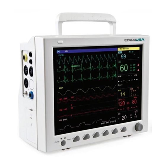
Patient Monitor User Manual Introduction Chapter 3 Introduction This user manual is based on the maximum configuration and therefore your monitor may not have all of the functions and options described in the manual. Also, illustrations in this manual serve as examples only and do not necessarily reflect the setup on your monitor. The content displayed on you monitor depends on the way it has been tailored for your hospital. - Page 24 Patient Monitor User Manual Introduction ③ ⑥ ② Figure 3-1 iM8/M8 Patient Monitor The monitor has 6 models: M8, M8A, M8B, iM8, iM8A and iM8B. Figure 3-2 iM8/M8 Patient Monitor - 15 -...
- Page 25 Patient Monitor User Manual Introduction Figure 3-3 iM8A/M8A Patient Monitor Figure 3-4 iM8B/M8B Patient Monitor The monitor can monitor the following parameters and waveforms: ECG: Heart Rate (HR) Maximum 7-channel Arrhythmia and ST-segment analysis (optional) - 16 -...
-
Page 26: Screen Display
Patient Monitor User Manual Introduction RESP: Respiration Rate (RR) Respiration Waveform Oxygen Saturation (SpO ), Pulse Rate (PR) Plethysmogram NIBP: Systolic Pressure (SYS), Diastolic Pressure (DIA), Mean Pressure (MAP), PR (NIBP) TEMP: Channel-1 Temperature (T1), Channel-2 Temperature (T2), Temperature Difference between two channels (TD) IBP: Channel-1 SYS, DIA, MAP Channel-2 SYS, DIA, MAP... - Page 27 Patient Monitor User Manual Introduction ① ③ ② ④ Figure 3-5 Main Display Information Area(① ④) The Information Area is at the top and bottom of the screen, displaying the operating state of the monitor and the status of the patient. The information area contains the following data: Bed number of the monitored patient Type of patient.
- Page 28 Patient Monitor User Manual Introduction gives information about remaining battery charge, estimated operating time and maintenance requirements; means there is no battery equipped in the monitor. Indicates the audio alarm is turned off. Indicates the audio alarm is paused. Displays beside a parameter to indicate the alarm is turned off. USB storage indicator STANDBY Select this item to enter Standby mode, the dialog pops up:...
- Page 29 Patient Monitor User Manual Introduction marked on the right of ECG waveform. The IBP waveform scale can also be selected according to the actual requirement. Its range is described in the part: IBP Monitoring. In the IBP waveform area, the waveform scale is displayed. The three dotted lines for each IBP waveform from up to down represent respectively the upper limit scale, reference scale and lower limit scale.
-
Page 30: Button Functions
Patient Monitor User Manual Introduction Refer to relative content of parameter for Alarm information and prompt. Charge Indicator and Charge Status To indicate the status of charging: When the battery is charged, the light color turns to orange. 3.3 Button Functions All the operations to the monitor can be finished by several buttons and a knob. -
Page 31: Interfaces
Patient Monitor User Manual Introduction Operating method: Move the cursor to the item where the operation is required. Press the knob. One of the following four situations may appear: 1. The cursor with background color may become a frame without background color, which implies that the content in the frame can change with the rotation of the knob. - Page 32 Patient Monitor User Manual Introduction 5. TEMP1 probe connector 6. TEMP2 probe connector 7. IBP2 transducer connector 8. SpO sensor connector Figure 3-9 Left Panel Rear Panel ① ⑤ ② ③ ⑥ ④ Figure 3-10 Rear Panel ① Network Interface (reserved): Standard RJ45 Socket, for connecting to MFM-CMS of the manufacturer.
-
Page 33: Built-In Rechargeable Battery
Patient Monitor User Manual Introduction ⑥ Power supply socket: 100 V-240 V~, 50 Hz/60 Hz. NOTE: The VGA function is optional. 3.5 Built-in Rechargeable Battery 3.5.1 Battery Safety Information WARNING Before using the rechargeable lithium-ion battery (hereinafter called battery), be sure to read the user manual and safety precautions thoroughly. -
Page 34: Checking Battery Performance
Patient Monitor User Manual Introduction battery status will be shown as the sign “ ”, which means no battery. One battery can power the monitor. Under the cable connectors is the cover of battery compartment. See Battery compartment in the following figure. Figure 3-11 Battery Compartment Battery status symbols show the status of battery and battery power remaining: Remaining battery power: 100%. -
Page 35: Recycling The Battery
Patient Monitor User Manual Introduction 3.5.5 Recycling the Battery When the battery no longer holds a charge, it should be replaced. Remove the old battery from the monitor and recycle it properly. 3.5.6 Maintaining the Battery Batteries should be conditioned regularly to maintain their useful life. Remove the batteries from the monitor if they are not used for a longer period of time. -
Page 36: Chapter 4 System Menu
Patient Monitor User Manual System Menu Chapter 4 System Menu The SYSTEM MENU is introduced in this chapter. The monitor features in flexible configurations. You can configure various aspects of the monitor, including the parameters to be monitored, sweeping speed of the waveforms, audio signal volume, and output content. -
Page 37: Patient Setup
Patient Monitor User Manual System Menu 4.1 Patient Setup Pick PATIENT SETUP in SYSTEM MENU to call up the following menu. Figure 4-3 Patient Setup You can set up the following patient information: Department in which the patient receives treatment. DEPT. -
Page 38: Default Setup
Patient Monitor User Manual System Menu Patient blood type (Pick A, B, O, AB, or N. N represents unknown BLOOD blood type) Admission of new patient NEW PATIENT Also in this menu, the user may select “NEW PATIENT” item to access “CONFIRM TO UPDATE PATIENT”... -
Page 39: Mark Event
Patient Monitor User Manual System Menu Figure 4-5 Default Menu In this sub-menu, you can select the factory default or the user-defined default. To check the configuration currently used, select SYSTEM MENU > DEFAULT. The one labeled with ( ) is current configuration. If there’s no labeled configuration, it means the currently used configuration is not one of them. -
Page 40: Face Select
Patient Monitor User Manual System Menu To mark the event: Use the rotary knob to select one from event A, B, C and D. There is a “@” signal for the one selected. To cancel your selection, repress the knob at selected item. Press EXIT to return to the previous menu. -
Page 41: Time Setup
Patient Monitor User Manual System Menu 4.5 Time Setup Select TIME SETUP item in SYSTEM SETUP menu to access the sub-menu of TIME SETUP as shown below. System time is in the format of MONTH-DAY-YEAR, DAY-MONTH-YEAR, YEAR-MONTH-DAY. Pick the item and turn the knob to modify the items. Select EXIT item to return to the previous menu. - Page 42 Patient Monitor User Manual System Menu In the sub-menu, the user may select the REC WAVE1, REC WAVE2 or REC WAVE3, a maximum of 3 waveforms can be printed out. The output waveforms can be selected for the following items: ECG1 waveform, ECG2 waveform and ECG3 waveform.
-
Page 43: Module Setup
Patient Monitor User Manual System Menu NOTE: The recorder is an optional part. If two same waveforms are selected, one of them will change to a different waveform automatically. When ECG waveforms are selected for printing, with gain of ×1, ×0.5 or ×0.25, X0.125, a 3-channel waveform can be printed out;... -
Page 44: Alarm Volume
Patient Monitor User Manual System Menu 4.10 Alarm Volume The system provides 10 levels of alarm volume and audio alarm off function. The system will give audio alarm prompt (except alarm sound) based on the selection. The user may select different levels of volume as per clinical requirement. The method is listed below: Press ALARM SETUP item in SYSTEM SETUP menu to call up ALARM SETUP sub-menu as shown below, in which the user may set up the alarm volume and other alarm information. -
Page 45: Maintenance
Patient Monitor User Manual System Menu 4.14 Maintenance Select MAINTAIN item in SYSTEM MENU to open the ENTER MAINTAIN PASSWORD dialog box as shown below, in which you can enter password and then customize maintenance settings. Factory maintenance function is only available for the service engineers of the manufacturer or representatives authorized by the manufacturer. - Page 46 CO MAINTAIN >>: Only applicable to EDAN EtCO module. In this menu, it displays BARO PRESS, GAS CELL PRESSURE, MODULE TEMP. You can set standard GAS TEMP (25 C is recommended) and CO value for CALIBRATE operation.
- Page 47 Patient Monitor User Manual System Menu Figure 4-15 Confirm Save Default Configuration Click on YES to save the current patient type configuration as the user default configuration. Click on NO to give up the operation. SERVER IP: The default server IP is 202.114.4.119, it can be changed by the user according to the IP address of PC installed with MFM-CMS of the manufacturer.
-
Page 48: Data Storing
Patient Monitor User Manual System Menu 4.15 Data Storing Users can store the measured data into USB storage by Data store function, query or delete data in the menu. The factory default of data store is in off status. If DATA STORE in FACTORY MAINTAIN is set to ON, user can select DATA STORE in SYSTEM MENU to call up the following dialog box: NOTE:... - Page 49 Patient Monitor User Manual System Menu Figure 4-18 Delete USB success SELECT DATA: select this item to query data. The dialog box displays as follows: Figure 4-19 Select data - DELETE ALL: users can delete all the data of selected patient ID by this item. -...
- Page 50 Patient Monitor User Manual System Menu Figure 4-20 Select data After selecting the time, the data will be imported from the USB storage to the monitor, it indicates as follows: Figure 4-21 Importing data - TREND TABLE: users can select this item by rotary knob after importing data, the real line box becomes broken line box, select the following contents to display: TREND TABLE, TREND GRAPH, NIBP RECALL, PATIENT INFO, FREEZE RECALL, ARR RECALL or ALARM LIST.
-
Page 51: Wireless Network With Router (Optional)
Patient Monitor User Manual System Menu Figure 4-22 Confirm to delete After deleting successfully, it indicates DELETE SUCCESS! NOTE: The data of the current monitoring patient ID can not be deleted. If the data has not been saved successfully because of the power supply off or USB storage failure, when the users queries data by SELECT DATA, the prompt pops up "INVALID DATA". - Page 52 Patient Monitor User Manual System Menu If signal is unstable, the signal transmission may be degraded. When the monitor is connected to MFM-CMS via the wireless network, the user should set the router to a secure encryption/authentication mode (Recommended option: WPA2-PSK, with a high complexity, non-dictionary password). For detailed specifications of router, please refer to the router’s user guide.
-
Page 53: Chapter 5 Face Select
Patient Monitor User Manual Face Select Chapter 5 Face Select This monitor has four different operating screens, which are STANDARD SCREEN, TREND SCREEN, oxyCRG SCREEN and LARGE FONT SCREEN. Users can select different operating screens for necessary information as requested. 5.1 Selecting Operating Screen In the SYSTEM MENU, select the FACE SELECT option in the SYSTEM SETUP menu to call up the dialog box as shown in the figure below. -
Page 54: Oxycrg Screen
Patient Monitor User Manual Face Select If multiple parameters are located at the same position on the trend graph, by selecting the corresponding hot key of a parameter on the trend graph, you can have the trend graph of this parameter displayed on the screen. - Page 55 Patient Monitor User Manual Face Select SELECT. There are three modes, see as follows: Figure 5-2 Large Font Face Select Three display modes 1. ECG+SpO +NIBP display mode: Figure 5-3 ECG+SpO +NIBP Display Mode - 46 -...
- Page 56 Patient Monitor User Manual Face Select 2. SpO +NIBP display mode: Figure 5-4 SpO +NIBP Display Mode 3. SpO display mode: Figure 5-5 SpO Display Mode Exit Large Font Screen In the LARGE FONT FACE SELECT menu, choose EXIT to return to FACE SELECT screen.
-
Page 57: Chapter 6 Alarms
Patient Monitor User Manual Alarms Chapter 6 Alarms This chapter gives general information about the alarm and measures to be taken accordingly. Alarm setup and prompt messages are provided in respective parameter setup sections. WARNING A potential hazard can exist if different alarm presets are used for the same or similar equipment in any single area, e.g. - Page 58 Patient Monitor User Manual Alarms NOTE: The Physiological Alarm area is on the upper right part of the screen. The Technical Alarm area is on the left side of the Physiological Alarm area. If the monitor is connected to the external alarm prompt system (e.g. the alarm speaker and indicator are connected onto the rear panel of the monitor), when alarm condition is active, the external alarm prompt system responds in the same way as the monitor.
-
Page 59: Alarm Setup
Patient Monitor User Manual Alarms Alarm Sound The high/medium/low-level alarms are indicated by the system in following different audio ways: Alarm level Audio prompt Mode is “DO-DO-DO------DO-DO, DO-DO-DO------DO-DO”, which High is triggered once every 10 seconds. Mode is “DO-DO-DO”, which is triggered once every 25 seconds. Medium Mode is “DO-”, which is triggered once every 30 seconds. - Page 60 Patient Monitor User Manual Alarms In the ALARM SETUP menu, select the ALM SEL item to set up the alarm information for the following parameters. They are HR, ST, PVCs, SpO , NIBP, IBP (1, 2), RESP, TEMP, and . For example: Method to set up HR alarm information: Step 1: Select the HR ALM SETUP option in the ALM SEL item.
-
Page 61: Alarm Cause
Patient Monitor User Manual Alarms NOTE: 1. When the monitor is connected with central monitoring system, you must set Disconnect Alarm to On. 2. If Disconnect Alarm occurs during audio alarm paused or audio alarm off status, the monitor will prompt a sounding alarm with information of Network Disconnect. During the network disconnected status, activating audio alarm paused or audio alarm off function can disable the audio alarm signal of Disconnect Alarm. -
Page 62: Audio Alarm Off
Patient Monitor User Manual Alarms 6.4 Audio Alarm Off To activate the audio alarm off function, you can select SYSTEM MENU > MAINTAIN > USER MAINTAIN > ALARM SETUP, and set Audio Alarm Off to ON, then press Mute button on the front panel and hold it for more than three seconds to turn off audio alarm. During the audio alarm off status, ... -
Page 63: When An Alarm Occurs
Patient Monitor User Manual Alarms limit of SpO will be displayed beside the parameter. When a parameter alarm is off, a symbol displays beside the parameter. If the alarms are turned off separately, they must be turned on separately. For the parameters whose alarms are set to ON, the alarm will be triggered when at least one of them exceeds the alarm limits. -
Page 64: Chapter 7 Alarm Information
Patient Monitor User Manual Alarm Information Chapter 7 Alarm Information 7.1 Physiological Alarm Information WARNING During monitoring, the physiological alarms including ASYSTOLE, VFIB/VTAC, RESP APNEA, SpO No Pulse, CO APNEA are preset to be on and cannot be turned off. Message Cause Alarm Level... - Page 65 Patient Monitor User Manual Alarm Information Message Cause Alarm Level NIBP MAP measuring value is below lower NM LOW User-selectable alarm limit. PR measuring value from the NIBP module is User-selectable PR (NIBP) High above upper alarm limit. PR measuring value from the NIBP module is User-selectable PR (NIBP) Low below lower alarm limit.
- Page 66 Patient Monitor User Manual Alarm Information Message Cause Alarm Level DIA measuring value of channel 2 is below ID2 LOW User-selectable lower alarm limit. MAP measuring value of channel 2 is above User-selectable IM2 HIGH upper alarm limit. MAP measuring value of channel 2 is below IM2 LOW User-selectable lower alarm limit.
- Page 67 Patient Monitor User Manual Alarm Information ARR physiological alarms: Applicable Prompt Occurring Condition Alarm Level Patient Type No QRS is detected for 4 consecutive ASYSTOLE All patients High seconds 4 consecutive seconds' fibrillation wave Without occurs, or each RR interval for 5 VFIB/VTAC High pacemaker...
-
Page 68: Technical Alarm Information
Patient Monitor User Manual Alarm Information Applicable Prompt Occurring Condition Alarm Level Patient Type Without Consistently irregular heart rhythm User-selectable pacemaker PACER CAPTURE: With complex detected in 300 ms after a pace User-selectable pacemaker pulse. PACER NOT PACED: no pace pulse With detected in 1.75 times RR interval after a User-selectable... - Page 69 Patient Monitor User Manual Alarm Information Message Cause Alarm level What to do adjust the electrode position on the patient in order to reduce the interference of cardiogenic artifact. Check whether the RESP cannot leads are well connected. RESP Noise measured Keep the patient calm for patient movement.
- Page 70 Patient Monitor User Manual Alarm Information Message Cause Alarm level What to do notify biomedical engineer or Manufacturer’s service staff. Check replace During the leakage leaking parts, if required, NIBP AIR LEAK test, the leakage ratio notify biomedical engineer or exceeds 6 mmHg/min.
- Page 71 Patient Monitor User Manual Alarm Information Message Cause Alarm level What to do weak. Due to motion, signal Make sure that the patient noise is too large or NIBP under monitoring Interference pulse rate motionless. regular. Maybe patient Maybe the patient blood NIBP Range blood pressure value...
- Page 72 COMM High biomedical STOP communication failure engineer or Manufacturer’s service staff. Applicable Stop using to EDAN measuring EtCO module exceeds function of module and Sensor Over working High module, Temp Respironics temperature range. notify...
- Page 73 1) For the Respironics the gas outlet module: is occluded. cannula/gas outlet is occluded. ADAPTER High EDAN EtCO OCCLUDE 2) For the EDAN module: EtCO module: The Replace water trap/ cannula/gas water trap; outlet is occluded. Check whether the cannula is...
- Page 74 Patient Monitor User Manual Alarm Information Message Cause Alarm level What to do Stop using alarm function, ZERO notify Zero calibration failure biomedical REQUIRED engineer or Only Manufacturer’s applicable service staff. Respironics Stop using INIT ERR module failure High alarm Module function;...
-
Page 75: Prompts
Patient Monitor User Manual Alarm Information Message Cause Alarm level What to do ECG electrode V falls ECG V LEAD off the skin or the ECG cable V falls off the monitor. ECG measuring signal SIGNAL Check lead connection and is beyond measuring patient condition EXCEED... -
Page 76: Adjustable Range Of Alarm Limits
Patient Monitor User Manual Alarm Information module is analyzing the patient signal and SEARCH searching for the pulse to compute the saturation, PULSE when sensor is connected with patient. The QRS template building required for Arr. ARR LEARNING Analysis is in process. IBP channel 1 sensor off during zeroing, or channel CH1 ZERO FAIL! 1 pressure exceeds the zero range. - Page 77 Patient Monitor User Manual Alarm Information RESP adjustable range of alarm limits are listed as follows (unit rpm): Patient Type ALM HI ALM LO adjustable range of alarm limits are listed as follows (unit %): ALM HI ALM LO PR adjustable range of alarm limits are listed as follows (unit bpm): ALM HI ALM LO PR (SpO...
- Page 78 Patient Monitor User Manual Alarm Information IBP adjustable range of alarm limits are listed as follows (unit mmHg): ALM HI ALM LO adjustable range of alarm limits are listed as follows: ALM HI ALM LO EtCO 150 mmHg 0 mmHg FiCO 50 mmHg 0 mmHg...
-
Page 79: Chapter 8 Freeze
Patient Monitor User Manual Freeze Chapter 8 Freeze 8.1 General When monitoring a patient, you may freeze the waveforms of interest so as to view them carefully. Generally you can review a frozen waveform of a maximum of 12 minutes. The Freeze function of this monitor has the following features: ... -
Page 80: Reviewing Frozen Waveform
Patient Monitor User Manual Freeze Figure 8-1 Frozen REC WAVE: it can be set to any waveform of 8s, such as IBP1, CO , PLETH etc. It can also be set to OFF. RECALL: Used to review frozen waveforms. ... -
Page 81: Chapter 9 Recording (Optional)
Patient Monitor User Manual Recording (Optional) Chapter 9 Recording (Optional) General information on recording Instructions for configuring and recording Recording messages 9.1 General Information on Recording A thermal dot matrices recorder with 48mm wide printout paper is used for the monitor. Performance of the Recorder ... - Page 82 Patient Monitor User Manual Recording (Optional) Real-time Recording Real-time recording starts as you press the RECORD button on the recorder. The waveforms for continual real-time recording and continuous 8 second recording are automatically set by the monitor (usually the first three waveforms displayed on the screen). You can also configure it through the menu.
-
Page 83: Recording Startup
Patient Monitor User Manual Recording (Optional) Notes on Recording Recording types: Real time Report Periodic Report Para Alarm Report Titration Table Arrhythmia Report Freeze Wave Report Trend graph Trend table Para Alarm Review NIBP Test Review Patient bed number, name, sex, height, weight, date of birth, admission date ... -
Page 84: Recorder Operations And Status Messages
Patient Monitor User Manual Recording (Optional) Trend table recording Access the TREND TABLE menu, then press the RECORD button to start recording. Arrhythmia review recording Enter the ECG SETUP menu via hot key, select ARR ANALYSE > ARR RECALL, then press the RECORD button to start recording. -
Page 85: Recorder Alarm Information
Patient Monitor User Manual Recording (Optional) Insert a new roll of paper into the paper cassette, printing side facing upwards. Ensure proper position and tidy margin. Pull about 2cm of the paper out, and close the recorder casing. NOTE: Be careful when inserting papers. -
Page 86: Chapter 10 Trend And Event
Patient Monitor User Manual Trend and Event Chapter 10 Trend and Event The monitor provides 96-hour trend data of all parameters, storage of 500 NIBP measurement results and 60 alarm events. This chapter gives detailed instruction for review of all data. 10.1 Trend Graph ... -
Page 87: Trend Table
Patient Monitor User Manual Trend and Event To select 1-hour or 96-hour trend graph Pick RESOLUTION item, choose 1 or 5 sec for 1-hour trend graph and 1, 5 or 10 min for 96-hour trend graph. To view other trend curves When "... - Page 88 Patient Monitor User Manual Trend and Event Figure 10-2 Trend Table Time corresponding to each group of trend data is displayed in the leftmost list with date in brackets. Marked event corresponds to marking time. Trend data of each parameter is divided into 8 groups.
-
Page 89: Nibp Recall
Patient Monitor User Manual Trend and Event To obtain trend data of different parameters Pick L-RIGHT to select one from the 8 groups of parameters. " " by the rightmost item indicates the next page available. " " by the leftmost item indicates the previous page available. Mark Event If an event is marked A, B, C, or D, the corresponding event type will display on the Time axis of the trend table. -
Page 90: Alarm Event Recall
Patient Monitor User Manual Trend and Event Data is listed chronologically from the latest to the earliest. 15 measurements can be displayed on one screen. Pick UP-DOWN to view up to 500 results of measurements. When you press the RECORD button, the recorder will print out the metrical data of current window. NOTE: When the user set the NIBP SETUP >... - Page 91 Patient Monitor User Manual Trend and Event ALARM RECALL The ALARM RECALL window is as shown below, in which the following data are displayed: ① Time span (Format: month-day-year hour: minute-month-day-year hour: minute). ② Event type. ③ Serial number (Format: NO. × × of × × ). ④...
-
Page 92: Chapter 11 Drug Calculation And Titration Table (Optional)
Patient Monitor User Manual Drug Calculation and Titration Table (Optional) Chapter 11 Drug Calculation and Titration Table (Optional) The patient monitor provides drug calculation and titration table display functions for fifteen drugs and outputs the content of titration table on the recorder. NOTE: The correctness of the input parameters and the suitability of the calculated results should be carefully verified. - Page 93 Patient Monitor User Manual Drug Calculation and Titration Table (Optional) Dose = Rate × Concentrate DRIP Rate = INF Rate / 60 × DROP Size Operating Method: In the Drug Calculation window, the operator should first select the name of the drug to be calculated, and then confirm the patient weight.
-
Page 94: Titration Table
Patient Monitor User Manual Drug Calculation and Titration Table (Optional) NOTE: This drug calculation function acts only as a calculator. That means the patient weight in Drug Calculation menu and it in Patient Information menu is independent from each other. Therefore if the Weight in Drug Calculation changes, it will not change in Patient Information. - Page 95 Patient Monitor User Manual Drug Calculation and Titration Table (Optional) Total amount, dose, volume, INF rate, drip rate, patient weight and drug name are displayed on the top of the titration table. The meaning of each English identifier is: AMOUNT: drug amount VOLUME: liquid volume DOSE/min: drug dose INF RATE: flow rate...
-
Page 96: Chapter 12 Maintenance/Cleaning
Patient Monitor User Manual Maintenance/ Cleaning Chapter 12 Maintenance/Cleaning WARNING Failure on the part of the responsible individual hospital or institution employing the use of this equipment to implement a satisfactory maintenance schedule may cause undue equipment failure and possible health hazards. If you discover a problem with any of the equipment, contact your service personnel, or your authorized supplier. -
Page 97: Care And Cleaning
Patient Monitor User Manual Maintenance/ Cleaning Maintenance and Test Schedule Frequency Check all monitoring functions At least once every two years, or as needed. and measuring functions 12.3 Care and Cleaning Use only the manufacturer’s approved substances and methods listed in this chapter to clean or disinfect your equipment. - Page 98 Patient Monitor User Manual Maintenance/ Cleaning Mild near neutral detergent Ethanol (75%) Isopropanol (70%) Cleaning agents should be applied and removed using a clean, soft, non-abrasive cloth or paper towel. 12.3.2.1 Cleaning the Monitor WARNING Before cleaning the monitor, make sure that the monitor is switched off and disconnected from the power line.
- Page 99 Patient Monitor User Manual Maintenance/ Cleaning Replacing the Air Bladder: After cleaning, replace the air bladder into the cuff following the steps below: Roll the bladder lengthwise and insert it into the cuff from the large opening at one end of the cuff.
- Page 100 Patient Monitor User Manual Maintenance/ Cleaning abnormal objects during deflation, the dust proof filter system can extend the pump’s lifetime and improve measurement accuracy. The recommended cleaning frequency is once every month, if the environment is dusty, the frequency may be twice every month, if the sound during inflation is noisier than usual, user needs to clean the dust-proof filter assembly according to the real condition.
-
Page 101: Disinfection
Patient Monitor User Manual Maintenance/ Cleaning 12.3.3 Disinfection For devices or accessories that have been in contact mucosal surface, High Level disinfection must occur, for all other accessories, low level disinfection is appropriate. Clean the monitor and reusable accessories before they are disinfected. The validated disinfectants for cleaning the monitor and reusable accessories are: ... - Page 102 Patient Monitor User Manual Maintenance/ Cleaning Disinfecting the Blood Pressure Cuff Disinfecting the Cuff: Take out the air bladder before disinfection. Wipe the cuff and the air bladder with a soft cloth dampened with the disinfectant solution. Leave the cuff and air bladder to air dry for at least 30 minutes. Replacing the Air Bladder: After disinfection, replace the air bladder into the cuff.
-
Page 103: Cleaning And Disinfecting Other Accessories
Patient Monitor User Manual Maintenance/ Cleaning 12.3.4 Cleaning and Disinfecting Other Accessories For cleaning and disinfecting other accessories, refer to the instructions delivered with the accessories. If the accessories are not accompanied by instructions, refer to this manual for the methods of cleaning and disinfecting the monitor. -
Page 104: Chapter 13 Monitoring Ecg/Resp
Patient Monitor User Manual Monitoring ECG/ RESP Chapter 13 Monitoring ECG/RESP 13.1 Overview Monitoring the ECG produces a continuous waveform of the patient's cardiac electric activity to enable an accurate assessment of his current physiological state. Only proper connection of the ECG cables can ensure satisfactory measurement. - Page 105 Patient Monitor User Manual Monitoring ECG/ RESP WARNING Place the electrode carefully and ensure a good contact. Check every day whether there is skin irritation resulted from the ECG electrodes. If yes, replace electrodes every 24 hours or change their sites. Store the electrodes in room temperature.
-
Page 106: Monitoring Procedure
Patient Monitor User Manual Monitoring ECG/ RESP NOTE: Interference from a non-grounded instrument near the patient and ESU interference can cause inaccuracy of the waveform. IEC/EN60601-1-2 (protection against radiation is 3 v/m) specifies that the electrical field density exceeding 3 v/m may cause measurement error in various frequencies. It is accordingly suggested that do not use equipment generating electrical radiation near ECG/RESP monitoring devices. -
Page 107: Placing Electrodes For Ecg Monitoring
Patient Monitor User Manual Monitoring ECG/ RESP WARNING Placed the electrode carefully and ensure a good contact. Check every day whether there is skin irritation resulted from the ECG electrodes. If yes, replace electrodes every 24 hours or change their sites. Check if the lead connection is correct before monitoring. - Page 108 Patient Monitor User Manual Monitoring ECG/ RESP Figure 13-1 Electrode Placement for 3-lead Set Electrode placement for 5-lead set Take the American standard for example, see Figure 13-2: Red (R) electrode - Be placed near the right shoulder, directly below the clavicle. ...
- Page 109 Patient Monitor User Manual Monitoring ECG/ RESP For 5-lead set, attach the C (V)-electrode to one of the indicated positions as below (Figure 13-3): V1 On the 4th intercostal space at the right sterna margin. V2 On the 4th intercostal space at the left sterna margin. ...
- Page 110 Patient Monitor User Manual Monitoring ECG/ RESP WARNING ECG cables can be damaged when connected to a patient during defibrillation or using other high frequency equipment. Check cables for functionality before using them again. It is recommended to use defibrillator-proof ECG lead to avoid burn. Using 5-lead ECG Set You can set the leads on ECG CH1 and ECG CH2 according to your needs.
-
Page 111: Ecg Screen Hot Keys
Patient Monitor User Manual Monitoring ECG/ RESP Figure 13-5 Standard ECG Waveform 13.4 ECG Screen Hot Keys ① ② ③ ④ ⑤ Figure 13-6 Hot Key for ECG [1]. Leads of channel 1: I, II, III, AVR, AVL, AVF, V1 to V6 are available. Leads on the ECG wave must not have the same name. -
Page 112: Ecg Menu
Patient Monitor User Manual Monitoring ECG/ RESP NOTE: Only in Diagnosis mode, the system can provide real signals filtered by the bandwidth of 0.05 Hz~150 In Monitor or Sugery mode, ECG waveforms may be distorted to different extents. In either of the latter two modes, the system can only show the basic ECG and the results of ST analysis may also be greatly affected. - Page 113 Patient Monitor User Manual Monitoring ECG/ RESP ALM HI: used to set up the upper limit of ECG alarm. ALM LO: used to set up the lower limit of ECG alarm. ECG alarm is activated when the heart beat exceeds set ALM HI value or falls below ALM LO value.
- Page 114 Patient Monitor User Manual Monitoring ECG/ RESP LEAD TYPE Users can select either 3 LEADS or 5 LEADS for this item. ECG DISPLAY: it varies according to LEAD TYPE. When LEAD TYPE is set to 3 LEADS, ECG DISPLAY can be set to NORMAL DISPLAY, it can display one ECG waveform on the main screen.
- Page 115 Patient Monitor User Manual Monitoring ECG/ RESP because of the lead off or other reasons, it can shift to other LEADS to collect an ECG waveform. BEAT VOL Six selections are available: 0, 1, 2, 3, 4, 5. “5” indicates maximum volume. “0” indicates no sound.
-
Page 116: St Segment Monitoring (Optional)
Patient Monitor User Manual Monitoring ECG/ RESP Figure 13-9 ADJUST WAVE POS Menu DEFAULT Pick the DEFAULT item to call up the ECG DEFAULT CONFIG dialog box, in which you can select the FACTORY DEFAULT CONFIG or the USER DEFAULT CONFIG item. - Page 117 Patient Monitor User Manual Monitoring ECG/ RESP recommended to select Diagnosis mode. Reliable ST monitoring may be influenced in following situations: You are unable to get a lead with low noise. If there is arrhythmia such as atrial fibrillation/flutter, the ECG baseline may be irregular.
- Page 118 Patient Monitor User Manual Monitoring ECG/ RESP ST ANALYSE Menu Figure 13-10 ST Analyse menu ST Analysis Alarm Setting ST ANALYSE: the switch for ST analysis. Set it to ON to activate the ST analysis or OFF to disable the ST analysis. ...
- Page 119 Patient Monitor User Manual Monitoring ECG/ RESP Figure 13-11 DEF POINT Window The operator can adjust the position of both ISO and ST measurement points. Set the reference point of ST measurement point to be peak point of R-wave. ST value Figure 13-12 DEF POINT The ST measurement for each beat complex is the vertical difference between the two measurement points.
-
Page 120: Arr. Monitoring (Optional)
Patient Monitor User Manual Monitoring ECG/ RESP The system displays the QRS complex template in the window. It is adjustable for the highlight bar in the window. You may select ISO or ST, switch the knob left or right to move the cursor line. - Page 121 Patient Monitor User Manual Monitoring ECG/ RESP WARNING This device is not intended for treatment. Selecting an ECG lead for Arrhythmia: In arrhythmia monitoring, it is important to select the appropriate lead. For non-paced patients, the guidelines are: - QRS should be tall and narrow (recommended amplitude> 0.5 mV) - R wave should be above or below the baseline (but not biphasic) - T wave should be smaller than 1/3 of the R wave height - P wave should be smaller than 1/5 of the R wave height.
- Page 122 Patient Monitor User Manual Monitoring ECG/ RESP ARR ANALYSE Menu Figure 13-13 ARR ANALYSE ARR ANALYSE: Pick ON during monitoring. It is set to OFF by default. PVCs ALM: Pick ON to enable prompt message when alarm occurs; pick OFF to disable the alarm function, and there will be a beside PVCs.
- Page 123 Patient Monitor User Manual Monitoring ECG/ RESP Figure 13-14 ARR RECALL UP-DOWN Observe the event lists on other pages. CURSOR Select the Arr. event, whose name is displayed in a protruding frame. DELETE Delete the selected Arr. event. ...
-
Page 124: Measuring Resp
Patient Monitor User Manual Monitoring ECG/ RESP Take care to initiate ARR selflearning only during periods of predominantly normal rhythm and when ECG signal is relatively noise-free. If ARR selflearning takes place during arrhythmia, the ectopics may be incorrectly learned as normal QRS complex. This may result in missed detection of subsequent events of arrhythmia. -
Page 125: How To Measure Resp
Patient Monitor User Manual Monitoring ECG/ RESP WARNING In manual detection mode, after changing the gain of the respiration wave, be sure to check the setting of hold high and hold low. When ECG electrode is placed on patient’s limb, the impedance respiration may be unreliable. -
Page 126: Installing Electrode For Resp Measurement
Patient Monitor User Manual Monitoring ECG/ RESP 13.8.3 Installing Electrode for RESP Measurement Placing the Electrodes for Respiratory Monitoring Yellow Black Green Figure 13-15 Electrodes Placement (5-lead) NOTE: 1. Place the red and green electrodes diagonally to optimize the respiration waveform. Avoid the liver area and the ventricles of the heart in the line between the RESP electrodes so as to avoid cardiac overlay or artifacts from pulsating blood flow. - Page 127 Patient Monitor User Manual Monitoring ECG/ RESP RESP alarm setting ALM: pick ON to enable prompt message during the RESP alarm; pick OFF to disable the besides “RESP”. alarm function, and there will be a WARNING In order to avoid endangering the patient’s life, the user should use this function cautiously.
- Page 128 Patient Monitor User Manual Monitoring ECG/ RESP HOLD HI and HOLD LO are unavailable, and the monitor can calculate the respiration rate automatically. When it is set to MANUAL mode, you can adjust the broken lines in RESP area by the HOLD HI and HOLD LO items. ...
-
Page 129: Chapter 14 Monitoring Spo
Patient Monitor User Manual Monitoring SpO Chapter 14 Monitoring SpO 14.1 Overview is used to measure arterial blood oxygen saturation, which is the percentage of oxyhemoglobin in the arterial blood. SpO parameter can also provide pulse rate (PR) and a plethysmogram wave (Pleth). -
Page 130: Monitoring Procedure
Patient Monitor User Manual Monitoring SpO When a trend toward patient deoxygenation is indicated, analyze the blood samples with a laboratory co-oximeter to completely understand the patient’s condition. waveform is not directly proportional to the pulse volume. The device is calibrated to display functional oxygen saturation. Functional tester or simulator can not be used to assess the SpO accuracy. -
Page 131: Measurement Limitations
Patient Monitor User Manual Monitoring SpO placed on the back of the hand. Clean and remove any substances such as nail polish from the application site. Periodically check to ensure that the sensor remains properly positioned on the patient. 14.4 Measurement Limitations Certain patient conditions can affect the measurements or cause the loss of the pulse signal. -
Page 132: Assessing The Validity Of A Spo Reading
Patient Monitor User Manual Monitoring SpO 14.5 Assessing the Validity of a SpO Reading You can check the quality of the pleth wave and the stability of the SpO values to assess whether the sensor functions properly and whether the SpO readings are valid. -
Page 133: Perfusion Index (Pi)
Patient Monitor User Manual Monitoring SpO 14.7 Perfusion Index (PI) PI, a numeric value indicating perfusion level, reflects the pulse strength at the monitoring site. As the measurement of SpO is based on the pulsation caused by the blood flow through the vessel, PI is in relation to the strength of the pulse. - Page 134 Patient Monitor User Manual Monitoring SpO PR SOUND It indicates the Pulse beep volume. Options are “0 - 5”. Beat frequency of pulse has positive correlation with measurement value. PITCH TONE When ON is enabled, the system will provide prompt sound with different tone for clinic under complex monitoring environment, based on the variance of SpO value.
-
Page 135: Chapter 15 Monitoring Nibp
Patient Monitor User Manual Monitoring NIBP Chapter 15 Monitoring NIBP 15.1 Overview This monitor uses the oscillometric method for measuring NIBP. It can be used for adult, pediatric and neonatal patients. It is also intended for use with pregnant, including pre-eclamptic patients. -
Page 136: Measurement Limitations
Patient Monitor User Manual Monitoring NIBP WARNING Measuring of blood pressure can temporarily cause malfunctioning of other medical monitoring devices on the same limb. 10 NIBP readings can be affected by the measurement site, the position of the patient, exercise, or the patient's physiologic conditions. 11 Continuous cuff pressure due to connection tubing kinking can block the blood flow, and may result in injury to the patient. -
Page 137: Measurement Methods
Patient Monitor User Manual Monitoring NIBP Patients with rapid blood pressure changes. Patients with severe shock or hypothermia that reduces blood flow to the peripheries. Patients with obesity, where a thick layer of fat surrounding a limb dampens the oscillations coming from the artery. - Page 138 Patient Monitor User Manual Monitoring NIBP Cuff Usage Ensure that the cuff is completely deflated. Apply the appropriate size cuff to the patient. (About the cuff size selection, please refer to Section NIBP Accessories). And make sure that the symbol "Φ" is over the appropriate artery.
- Page 139 Patient Monitor User Manual Monitoring NIBP error. 4. Please select the cuff with the suitable size. An unsuitable cuff may cause incorrect measurements. 5. Avoid incursion of liquid into the cuff. If this happens, please desiccate the cuff completely. Operation Hints 1.
-
Page 140: Nibp Setup
Patient Monitor User Manual Monitoring NIBP WARNING If liquid is inadvertently splashed on the equipment or its accessories, or enters the conduit or inside the monitor, contact local Customer Service Center. 15.6 NIBP SETUP Pick the NIBP hot key on the main screen to open the NIBP SETUP. ... -
Page 141: Resetting Nibp
Patient Monitor User Manual Monitoring NIBP 15.7 Resetting NIBP When the pressure does not work properly and the system fails to give a message for the problem, click on RESET via USER MAINTAIN > NIBP MAINTAIN to activate self-test procedure, and thus restore the system from abnormal performance. - Page 142 Patient Monitor User Manual Monitoring NIBP it indicates that the airway may have air leaks. In this case, the user should check for loose connection. After confirming secure connections, the user should re-perform the pneumatic test. If the failure prompt still appears, please contact the manufacturer for repair.
-
Page 143: Chapter 16 Monitoring Temp
Patient Monitor User Manual Monitoring TEMP Chapter 16 Monitoring TEMP 16.1 TEMP Monitoring Body temperature is measured by means of a thermistor probe (a semiconductor whose resistance changes with temperature) that is applied to the skin or to the rectum. Two TEMP probes can be used simultaneously to measure two TEMP values, and get the temperature difference. - Page 144 Patient Monitor User Manual Monitoring TEMP Figure 16-1 TEMP SETUP ALM: pick ON to enable prompt message during the TEMP alarm; pick OFF to disable the alarm function, and prompt the symbol besides TEMP numeric. WARNING In order to avoid endangering the patient’s life, the user should use this function cautiously.
-
Page 145: Chapter 17 Monitoring Ibp (Optional)
Patient Monitor User Manual Monitoring IBP (Optional) Chapter 17 Monitoring IBP (Optional) 17.1 Introduction The monitor measures direct blood pressure (SYS, DIA and MAP) of one selected blood vessel through two channels, and displays two waveforms of measured direct blood pressure (SYS, DIA and MAP). -
Page 146: Monitoring Procedure
Patient Monitor User Manual Monitoring IBP (Optional) NOTE: Use only the pressure transducer listed in the IBP Accessories. If measuring intracranial pressure (ICP) on a sitting patient, adjust the transducer on the same level with the top of the patient’s ear. Incorrect leveling may lead incorrect values. -
Page 147: Ibp Menu
Patient Monitor User Manual Monitoring IBP (Optional) 5. Position the transducer so that it is at the same level with the patient’s heart, approximately mid-axillary line. 6. Check if you have selected the correct label name. See the next section for details. 7. - Page 148 Patient Monitor User Manual Monitoring IBP (Optional) Pick the IBP SETUP item to call up the IBP SETUP menu shown as follows: Figure 17-3 IBP SETUP Menu The items to be set up in the menu include: ALM: select ON to enable alarm prompt during IBP alarm. Select OFF to disable audio alarm and prompt the symbol beside IBP numeric.
- Page 149 Patient Monitor User Manual Monitoring IBP (Optional) SCALE ADJUST: used to access the sub-menu of IBP SCALE ADJUST, in which the user may adjust the position of the high, reference and low scales for the two waveforms displayed on the screen. ...
- Page 150 Patient Monitor User Manual Monitoring IBP (Optional) NOTE: It is the responsibility of the user to ensure that a zero procedure has recently been done on the transducer: otherwise there will be no recent, valid zero value for the instrument to use, which may result in inaccurate measurement results.
- Page 151 Patient Monitor User Manual Monitoring IBP (Optional) Figure 17-6 IBP Calibration Menu Calibrate the transducer: Turn the knob to select the item CH1 CAL VALUE, press and turn the knob to select the pressure value to be calibrated for channel 1. Then turn the knob to select CALIBRATE in the menu to start calibrating channel 1.
- Page 152 Patient Monitor User Manual Monitoring IBP (Optional) CAUTION Mercury calibration should be performed by the biomedical engineering department either whenever a new transducer is used, or as frequently as dictated by your Hospital Procedures Policy. The purpose of the calibration is to ensure that the system gives you accurate measurements.
- Page 153 Patient Monitor User Manual Monitoring IBP (Optional) “IN DEMO, FAIL!” Make sure that the monitor is not in DEMO mode. Contact service technician if necessary. “PRESSURE OVER RANGE, FAIL!” Make sure that you have selected transducer value in IBP CAL, then start the calibration. IBP SCALE ADJUST Submenu Figure 17-8 IBP SCALE ADJUST Menu The waveform and corresponding scale appears in the IBP Waveform Area with 3 dotted lines...
-
Page 154: Chapter 18 Monitoring Co (Optional)
18.1 General This chapter offers some relevant data concerning CO monitoring. The monitor provides the Sidestream and MainStream method for CO monitoring. EDAN EtCO module and Respironics Sidestream CO module are used for sidestream measuring, and Respironics Mainstream CO module is used for mainstream measuring. -
Page 155: Monitoring Procedure
CO measurement for the first time, you must set the correct altitude. Incorrect altitude settings can cause incorrect CO readings. EDAN EtCO module is equipped with automatic air pressure compensation, and manual setting is not required. -
Page 156: Zeroing The Sensor
4. The messages indicate: “zeroing”, “zero successfully”. After the zero calibration is finished, the user can start CO Monitoring. NOTE: For EDAN module, automatic zero is performed when turning on the monitor. 18.2.2 Sidestream CO Module 18.2.2.1 Measurement Steps EDAN EtCO... - Page 157 Patient Monitor User Manual Monitoring CO (Optional) NOTE: 1. Disconnect the water trap from the holder or set WORK MODE to STANDBY when the module is not in use. 2. To avoid patient cross infection, do not connect the exhaust tube to the ventilator circuit.
- Page 158 Patient Monitor User Manual Monitoring CO (Optional) Figure 18-3 Air adapter For non-intubated patients: Place the nasal cannula onto the patient. Figure 18-4 Place the nasal cannula NOTE: You must perform a zero calibration as described in this procedure each time the ambient temperature changes more than 10 °...
-
Page 159: Mainstream Co 2 Module
Patient Monitor User Manual Monitoring CO (Optional) 18.2.2.2 Removing Exhaust Gases from the System WARNING Do not connect the exhaust tube to the ventilator circuit, connect the outlet to a scavenging system, cross infection can occur if sampling gas is returned to the breathing system. - Page 160 Patient Monitor User Manual Monitoring CO (Optional) Figure 18-6 Connecting sensor To zero the sensor, please refer to zeroing the sensor. Install the airway adapter at the proximal end of the circuit between the elbow and the ventilator Y-section. Figure 18-7 Connecting airway adapter WARNING No routine user calibration is required.
-
Page 161: Co 2 Setup
Patient Monitor User Manual Monitoring CO (Optional) Periodically check the flow sensor and tubing in case of excessive moisture or secretion buildup. Always connect the airway adapter to the sensor before inserting the airway adapter into the breathing circuit. In reverse, always remove the airway adapter from the breathing circuit before removing the sensor. - Page 162 Patient Monitor User Manual Monitoring CO (Optional) WORK MODE: to change the work mode of CO with between MEASURE and STANDBY. The default is STANDBY. When it is required to monitor CO , you should select MEASURE. In STANDBY mode, the air pump in SideStream module is disabled, which decreases the power consumption and extends the lifecycle of IR source and the whole module.
- Page 163 ■ PUMP RATE: to adjust the pump rate of the air pump in the CO module. 70ml/min and 100ml/min are selectable, which is only applicable to EDAN EtCO module. ■ COMPENSATE: to perform different compensate operations as per the selection of the user.
-
Page 164: Setting Co 2 Corrections
O and Helium in the mixture all influence CO absorption. If values seem inaccurately high or low, check that the monitor is using the appropriate corrections. For the EDAN sidestream module, the following items are available in the CO SETUP > OTHER SETUP menu: N... - Page 165 Patient Monitor User Manual Monitoring CO (Optional) For the Respironics CO modules, there are BARO PRESS, O COMPENS, ANE AGENT, and BALAN GAS in CO SETUP > OTHER SETUP menu. The concentration of compensated gas (including O and AG) should be set based on the current gas concentration which is supplied for patient.
-
Page 166: Chapter 19 Accessories
Patient Monitor User Manual Accessories Chapter 19 Accessories You can order accessories from manufacturer’s supplies or consult your local representative of the manufacturer for details. WARNING Never reuse disposable transducers, sensors, accessories and their casing that are intended for single use; or only use them on a single patient. Reuse may compromise device functionality and system performance and cause a potential hazard. - Page 167 Patient Monitor User Manual Accessories Infant Single-Patient SpO sensor SHD-I (big toe, for patients 01.57.471237 between 3kg to 20 kg) Neonate Single-Patient SpO sensor SHD-N (foot, for patients less 01.57.471238 than 3 kg) 01.13.036336 adapter cable, extended (Lemo to DB9) NIBP 01.57.471326 NIBP Cuff, E5, Infant, 10 cm -15 cm, reusable...
- Page 168 Patient Monitor User Manual Accessories 01.15.040420 Skin Temperature Probe (10K) 01.15.040421 Rectal/Oral Temperature Probe (10K) 01.57.471391 ECG Cable, IEC, 3 lead, 6 pin, snap, ESU-proof 01.57.471383 ECG Cable, IEC, 3 lead, 6 pin, snap, Defib-proof 01.57.471390 ECG Cable, AHA, 3 lead, 6 pin, clip, ESU-proof 01.57.471382 ECG Cable, AHA,3 lead, 6 pin, clip, Defib-proof 01.57.471384...
- Page 169 Patient Monitor User Manual Accessories 01.57.471469 5-Lead, 6-pin, Defib-proof, Clip, IEC, 3.4 m, Reusable 01.57.471470 5-lead, 6-pin, Defib-proof, Clip, AHA, 3.4 m, Reusable 01.57.471471 5-Lead, 6-pin, Defib-proof, Snap, IEC, 3.4 m, Reusable 01.57.471472 5-Lead, 6-pin, Defib-proof, Snap, AHA, 3.4 m, Reusable 01.57.471477 5-lead, 6-pin, ESU-proof, Clip, IEC, 3.4 m, Reusable 01.57.471478...
- Page 170 3-lead, 6-pin, Defib-proof, AHA, Banana 01.57.471897 Disposable ECG Electrodes 01.57.471898 Disposable ECG Electrodes For EDAN Module 02.01.210520 Dewatering Cup (Single Patient Use, Adult/Pediatric 10ml) 01.57.471275 Sampling Line with Male Luer Lock, 2.0 m All Purpose Sampling Cannula without filter (Non Sterile). Size: 01.57.471282...
- Page 171 Patient Monitor User Manual Accessories Adult Nasal CO with O delivery sampling cannula (Respironics 01.57.078142 3469ADU-00) Pediatric Nasal CO with O delivery sampling cannula (Respironics 01.57.078143 3469PED-00) Infant Nasal CO with O delivery sampling cannula (Respironics 01.57.078144 3469INF-00) 01.57.101019 Adult Nasal/Oral CO sampling cannula (Respironics 3470ADU-00) Pediatric Nasal/Oral...
- Page 172 Patient Monitor User Manual Accessories 01.57.78035 Printing Paper 02.04.241047 Unicode recorder assembly kit, Serial/parallel port 02.01.101206 Wireless AP upgrade assembly bag 02.04.240445 Patient Monitor wireless AP assembly bag 02.04.241689 Patient monitor mounting arm assembly kit (iM8/iM9/iM80) 83.60.261117 MT206 Trolley (M8\M9), plastic caster 83.60.261082 MT-207 Trolley (iM8\iM9), metal caster 02.04.101976...
-
Page 173: Chapter 20 Warranty And Service
Patient Monitor User Manual Warranty and Service Chapter 20 Warranty and Service 20.1 Warranty The manufacturer warrants that the manufacturer’s products meet the labeled specifications of the products and will be free from defects in materials and workmanship that occur within warranty period. -
Page 174: Appendix I Specifications
Patient Monitor User Manual Specifications Appendix I Specifications A1.1 Classification Anti-electroshock Type Class I equipment and internal powered equipment Anti-electroshock Degree ECG (RESP), TEMP, IBP CF , NIBP, CO Ingress Protection IPX1 Degree of Safety in Presence of Not suitable for use in presence of flammable gases Flammable Gases Disinfection/Sterilizing method Refer to Chapter 12 for details. -
Page 175: A1.2.2 Environment
Patient Monitor User Manual Specifications Shell figure / Screen Product Size (W× H× D) Weight Remark size <5kg 320 mm× 265 mm× 150 mm Square /10.4-inch Square /10.1-inch <5kg 320 mm× 265 mm× 150 mm Wide screen A1.2.2 Environment The monitor may not meet the performance specifications given here if stored or used outside the specified temperature and humidity ranges. -
Page 176: A1.2.3 Function Configuration
Patient Monitor User Manual Specifications A1.2.3 Function Configuration Product Standard Configuration Optional Configuration ECG, RESP, SpO , NIBP, TEMP IBP, CO , recorder iM8A ECG, RESP, SpO , NIBP, TEMP IBP, CO , recorder iM8B ECG, RESP, SpO , NIBP, TEMP IBP, CO , recorder ECG, RESP, SpO... -
Page 177: A1.2.6 Recorder (Optional)
Patient Monitor User Manual Specifications 2500 mAh : 2.5 h Typical Working Period 5000 mAh At 25 C, with a new fully charged battery, in continual measuring mode and NIBP automatic measuring mode with the operating interval of 15 minutes; ECG/TEMP module connected;... -
Page 178: A1.2.8 Ecg
Patient Monitor User Manual Specifications A1.2.8 ECG Complies with IEC 60601-2-27: 2011. 3-Lead: I, II, III Lead Mode 5-Lead: I, II, III, aVR, aVL, aVF, V Lead naming style AHA, IEC 1.25 mm/mV (× 0.125), 2.5 mm/mV (× 0.25), 5 mm/mV ☆... - Page 179 Patient Monitor User Manual Specifications <30 μVPP ☆System noise Cut mode: 300 W ☆ESU Protection Coagulation mode: 100 W Restore time: ≤10 s Electrosurgical Interference Test according to ANSI/AAMI EC13:2002, Sect. 5.2.9.14. Suppression Complied with ANSI/AAMI EC13:2002, Sect. 4.2.9.14. Pace Pulse Pulse is marked if the requirements of IEC 60601-2-27: 2011, Sect.
- Page 180 Patient Monitor User Manual Specifications Accuracy ± 0.02 mV or 10% (-0.8 mV to +0.8 mV), whichever is greater. Beyond this range: not specified. Resolution 0.01 mV HR averaging method Method 1 Heart rate is computed by excluding the minimum and maximum values from the 12 most recent RR intervals and averaging the residual 10 RR intervals.
-
Page 181: A1.2.9 Resp
Patient Monitor User Manual Specifications Response time of Heart Rate HR range: 80 bpm to 120 bpm Meter to Change in HR Range : Within 11 s HR range: 80 bpm to 40 bpm Range : Within 11 s Tall T-wave Rejection Complies with 60601-2-27:... -
Page 182: A1.2.10 Nibp
Patient Monitor User Manual Specifications 6 rpm to 150 rpm: 2 rpm Neo/Ped 0 rpm to 5 rpm: Undefined <500 μA, sinusoid, 62.8 kHz (10%) Respiration excitation waveform Within baseline impedance range: 0.3 Ω Measuring Sensitivity 0.25, 0.5, 1, 2, 3, 4, 5 ☆Gain selection ☆Sweep 6.25 mm/s, 12.5 mm/s, 25.0 mm/s, 50.0 mm/s... -
Page 183: A1.2.11 Spo
Patient Monitor User Manual Specifications Adult Mode SYS: 40 mmHg to 270 mmHg DIA: 10 mmHg to 215 mmHg MAP: 20 mmHg to 235 mmHg Pediatric Mode SYS: 40 mmHg to 230 mmHg DIA: 10 mmHg to 180 mmHg MAP: 20 mmHg to 195 mmHg Neonatal Mode SYS: 40 mmHg to 135 mmHg DIA: 10 mmHg to 100 mmHg... -
Page 184: A1.2.12 Pr
Patient Monitor User Manual Specifications ☆Accuracy 2% (70% to 100% SpO Adult (including Pediatric) Undefined (0% to 69% SpO 3% (70% to 100% SpO Neonatal Undefined (0% to 69% SpO Measuring Range 0-10. It displays 0 for invalid PI value. Resolution Sensors Wave Length... -
Page 185: A1.2.14 Ibp (Optional)
DC~12.5 Hz; DC~40 Hz Pressure sensor 5 (μV/V/mmHg) Sensitivity 300 Ω to 3000 Ω Impedance Volume Displacement 7.4 x 10 /100mmHg A1.2.15 CO (Optional) Complies with ISO 80601-2-55: 2011. EDAN EtCO Module Intended Adult, pediatric, neonatal patient - 176 -... - Page 186 Patient Monitor User Manual Specifications Measurement Non-dispersive infrared gas analysis (NDIR) method Unit mmHg, %, kPa 0 mmHg to 150 mmHg (0% to 20%) ☆ Measuring Range AwRR 2 rpm to 150 rpm EtCO 1 mmHg Resolution FiCO 1 mmHg AwRR 1 rpm ...
- Page 187 Patient Monitor User Manual Specifications Warm-up Display waveform within 20 s; Reach the design accuracy within 2 minutes. time < 400 ms (with 2 m gas sampling tube, sample gas flowrate: 100 ml/min) Rise time < 500 ms (with 2 m gas sampling tube, sample gas flowrate: 70 ml/min) <...
- Page 188 Patient Monitor User Manual Specifications AwRR ≤ 60rpm, meet the accuracy with 2 m gas sampling tube, sample gas mentioned above; flowrate: 70 ml/min) AwRR > 60 rpm, EtCO descends AwRR > 90 rpm, EtCO descends 10%; AwRR > 120rpm, EtCO descends 15%;...
- Page 189 Patient Monitor User Manual Specifications 1 rpm ☆AwRR 50 ml /min 10 ml /min Sample Flow Rate (Sidestream) Compensation Range 0% to 100% Resolution Default Anesthetic Gas Compensation Range 0% to 20% Resolution 0.1% Default 0.0% Balance Gas Compensation Options: N O, helium, room air Barometric pressure...
- Page 190 Patient Monitor User Manual Specifications Data Sample Rate 100 Hz Rise Time/Response < 60 ms Time(Mainstream) Sensor Response time <3 seconds - includes transport time and rise time (Sidestream) Interfering Gas and Vapor Effect on EtCO Measurement Values: Gas or vapour Gas level (%) Quantitative effect/Comments Nitrous oxide...
-
Page 191: A1.2.16 Interfaces
Patient Monitor User Manual Specifications NOTE: Respiration Rate accuracy was verified by using a solenoid test setup to deliver a square wave of known CO concentration to the device. 5% and 10% CO concentrations were used. Respiration rate was varied over the range of the device. Pass/Fail criteria was comparison of the respiratory rate output from the sensor to the frequency of the square wave. -
Page 192: Appendix Ii Emc Information
A2.1 Electromagnetic Emissions Guidance and manufacture’s declaration – electromagnetic emission The patient monitors of iM8 & M8 series patient monitor are intended for use in the electromagnetic environment specified below. The customer or the user of the iM8 & M8 series patient monitor should assure that they are used in such an environment. - Page 193 Patient Monitor User Manual EMC Information Electromagnetic Immunity test IEC/EN 60601 test level Compliance level environment - guidance 8 kV contact 8 kV contact Electrostatic Floors should be wood, discharge (ESD) concrete or ceramic tile. 15 kV air 15 kV air If floor are covered with IEC/EN 61000-4-2 synthetic material, the...
-
Page 194: A2.3 Electromagnetic Immunity
A2.3 Electromagnetic Immunity Guidance and manufacture’s declaration – electromagnetic immunity The patient monitors of iM8 & M8 series are intended for use in the electromagnetic environment specified below. The customer or the user of iM8 & M8 series patient monitors should assure that they are used in such an environment. - Page 195 & M8 series are used exceeds the applicable RF compliance level above, the patient monitors of iM8 & M8 series should be observed to verify normal operation. If abnormal performance is observed, additional measures may be necessary, such as reorienting or relocating the patient monitors of iM8 &...
- Page 196 Patient Monitor User Manual EMC Information Table 1 Test specifications for ENCLOSURE PORT IMMUNITY to RF wireless communications equipment Test Band Service Modulation Maximum Distance Immunity frequency (MHz) power test level (MHz) (V/m) Pulse 380-390 TETRA 400 modulation 18 Hz ±...
-
Page 197: A2.4 Recommended Separation Distances
Recommended separation distances between portable and mobile RF communications equipment and the monitor The patient monitors of iM8 & M8 series are intended for use in an electromagnetic environment in which radiated RF disturbances are controlled. The customer or the user of the iM8 &... -
Page 198: Appendix Iii Default Settings
Patient Monitor User Manual Default Settings Appendix III Default Settings This appendix documents the most important default settings of your monitor as it is delivered from the factory. NOTE: If your monitor has been ordered preconfigured to your requirements, the settings at delivery will be different from those listed here. - Page 199 Patient Monitor User Manual Default Settings ST Analysis ST Analysis Alarm Switch Alarm Level Medium Alarm Record Alarm High Limit (ST-X) Alarm Low Limit -0.2 (ST-X) X stands forⅠ, Ⅱ, Ⅲ, aVR, aVL, aVF, V, V1, V2, V3, V4, V5 or V6. ARR Analysis ARR Analysis PVCs Alarm Level...
-
Page 200: A3.4 Resp
Patient Monitor User Manual Default Settings A3.4 RESP RESP Settings Alarm Switch Alarm Record Alarm Level Medium Alarm High Limit Alarm Low Limit Apnea Time 20 s Calculation Type Auto Ⅱ Resp Type Sweep 12.5 mm/s Amplitude A3.5 SpO Settings Alarm Switch Alarm Record Alarm Level... -
Page 201: A3.7 Nibp
Patient Monitor User Manual Default Settings A3.7 NIBP NIBP Settings Alarm Switch Alarm Record Alarm Level Medium Alarm High Limit (SYS) Alarm Low Limit (SYS) Alarm High Limit (Map) Alarm Low Limit (Map) Alarm High Limit (Dia) Alarm Low Limit (Dia) Inflation value Unit mmHg... -
Page 202: A3.10 Co
Patient Monitor User Manual Default Settings Unit mmHg Filter 12.5 Hz SYS, DIA, MAP SYS, DIA, MAP SYS, DIA, MAP Alarm High Limit (ART, 160, 90, 110 120, 70, 90 90, 60, 70 P1, P2) Alarm Low Limit (ART, 90, 50, 70 70, 40, 50 55, 20, 35 P1, P2) -
Page 203: Appendix Iv Abbreviations
Patient Monitor User Manual Abbreviations Appendix IV Abbreviations Abbr English Full Name/Description Alternating current Adult Arterial Left foot augmented lead Left arm augmented lead Right arm augmented lead awRR Airway respiration rate Blood pressure BTPS Body temperature and pressure, saturated CISPR International Special Committee on Radio Interference... - Page 204 Patient Monitor User Manual Abbreviations Abbr English Full Name/Description FiCO Fraction of inspired carbon dioxide Fraction of inspired nitrous oxide Fraction of inspired oxygen Halothane Hemoglobin Hb-CO Carbon mono-xide hemoglobin Heart rate Intracranial pressure Intensive care unit Identification International Electrotechnical Commission IEEE Institute of Electrical and Electronic Engineers Isoflurane...
- Page 205 Patient Monitor User Manual Abbreviations Abbr English Full Name/Description Premature ventricular complex Right Right arm Right arterial pressure Resp Respiration Reduced hemoglobin Right leg Respiration Rate Sevoflurane Pulse Oxygen Saturation Systolic pressure Temperature difference TEMP Temperature Universal serial bus - 196 -...
Need help?
Do you have a question about the M8 Series and is the answer not in the manual?
Questions and answers