Advertisement
Quick Links
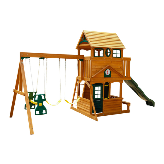
ASHBERRY PLAY SYSTEM - F23075
INSTALLATION AND OPERATING INSTRUCTIONS
31'-7"
19'-7"
10-14 Hrs
Two person
assembly
KidKraft, Inc.
4630 Olin Road
Dallas, Texas 75244 USA
customerservice@kidkraft.com
canadacustomerservice@kidkraft.com
1.800.933.0771
972.385.0100
For online parts replacement visit
https://parts.kidkraft.com/
WARNING
and give them to any future owner of this play system. Manufacturer contact information provided below.
OBSTACLE FREE SAFETY ZONE - 31'7" x 26' area requires Protective Surfacing. See page 3.
MAXIMUM VERTICAL FALL HEIGHT - 6'5"
CAPACITY - 10 Users Maximum, Ages 3 to 10; Weight Limit 110 lbs. (49.9 kg) per child.
RESIDENTIAL HOME USE ONLY. Not intended for public areas such as schools, churches, nurseries, day cares or parks.
Warning. Only for domestic use.
KidKraft Netherlands BV
Olympisch Stadion 8
1076 DE Amsterdam
The Netherlands
europecustomerservice@kidkraft.com
+31 20 305 8620 M-F from 09:00 to 17:30
(GMT+1)
For online parts replacement visit
https://parts.kidkraft.eu/
To reduce the risk of serious injury or death, you must read and
follow these instructions. Keep and refer to these instructions often
Table of Contents
Warnings and Safe Play Instructions. . . . . . . . . . . . . . . pg. 2
Protective Surfacing Guidelines. . . . . . . . . . . . . . . . . . . pg. 3
Instructions for Proper Maintenance . . . . . . . . . . . . . . . pg. 4
About Our Wood - Limited Warranty . . . . . . . . . . . . . . pg. 5
Keys to Assembly Success . . . . . . . . . . . . . . . . . . . . . . pg. 6
Metric Conversion Sheets . . . . . . . . . . . . . . . . . . . . . pg. 7,8
Part ID . . . . . . . . . . . . . . . . . . . . . . . . . . . . . . . . . . . . . . . pg. 9
Installation of I.D./Warning Plaque . . . . . . . . . . . .Final Step
9403075
Rev 06/02/2021
Advertisement

Related Manuals for KidKraft ASHBERRY


Summary of Contents for KidKraft ASHBERRY
-
Page 1: Table Of Contents
ASHBERRY PLAY SYSTEM – F23075 INSTALLATION AND OPERATING INSTRUCTIONS WARNING 31'-7" To reduce the risk of serious injury or death, you must read and follow these instructions. Keep and refer to these instructions often 19'-7" and give them to any future owner of this play system. Manufacturer contact information provided below. -
Page 2: Warnings And Safe Play Instructions
Warnings and Safe Play Instructions CONTINUOUS ADULT SUPERVISION REQUIRED. Most serious injuries and deaths on playground equipment have occurred while children were unsupervised! Our products are designed to meet mandatory and voluntary safety standards. Complying with all warnings and recommendations in these instructions will reduce the risk of serious or fatal injury to children using this play system. -
Page 3: Protective Surfacing Guidelines
Protective Surfacing - Reducing Risk of Serious Head Injury From Falls. One of the most important things you can do to reduce the likelihood of serious head injuries is to install shock-absorbing protective surfacing under and around your play equipment. The protective surfacing should be applied to a depth that is suitable for the equipment height in accordance with ASTM F1292. -
Page 4: Instructions For Proper Maintenance
Instructions for Proper Maintenance Your KidKraft Play System is designed and constructed of quality materials with your child’s safety in mind. As with all outdoor products used by children, it will weather and wear. To maximize the enjoyment, safety and life of your Play Set, it is important that you, the owner, properly maintain it. -
Page 5: About Our Wood - Limited Warranty
About Our Wood KidKraft Premium Play Systems uses only premium playset lumber, ensuring the safest product for your children’s use. Although we take great care in selecting the best quality lumber available, wood is still a product of nature and susceptible to weathering which can change the appearance of your set. -
Page 6: Keys To Assembly Success
Keys to Assembly Success Tools Required • Tape Measure • #1, #2 & #3 Phillips • Open End Wrench • 3/16” Hex Key • Carpenters Level or Robertson Bits (7/16”, 1/2” & 9/16”) • 8’ Step Ladder • Carpenters Square or Screwdriver •... -
Page 9: Part Id
Part Identification (Reduced Part Size) Part Identification (Reduced Part Size) Part Identification (Reduced Part Size) Part Identification (Reduced Part Size) Actual Size Nominal Size 1pc. - 2160 - Narrow Siding 3/8 x 3 x 29-5/16" - Box 2 - 3632160 "... - Page 10 Part Identification (Reduced Part Size) Part Identification (Reduced Part Size) Trim 5/8 x 1 3/4 x 16-1/4" Actual Size 7pc. - 2133 - - Box 3 - 3632133 Nominal Size " x 3⅜" 1 x 4 ⅝ " x 4½" 1 x 5 ⅝...
- Page 11 Part Identification (Reduced Part Size) Part Identification (Reduced Part Size) Middle Front 1 x 5 x 65-5/8" 3632125 1pc. - 2125 - - Box 3 - Nominal Size Actual Size 1 x 5 " x 4½" ⅝ 1 x 6 "...
- Page 12 Part Identification (Reduced Part Size) Part Identification (Reduced Part Size) Bench Post 5/4 x 4 x 14" 2pc. - 2105 - - Box 2 - 3632105 Nominal Size Actual Size 5/4 x 4 1" x 3½" 5/4 x 5 1" x 4½" Back Wall Support 5/4 x 4 x 31"...
- Page 13 Part Identification (Reduced Part Size) Part Identification (Reduced Part Size) Access Rail Left 2 x 3 x 56-1/8" 1pc. - 2101 - - Box 3 - 3632101 Nominal Size Actual Size 2 x 2 1½" x 1½" 2 x 3 1⅜"...
- Page 14 Part Identification (Reduced Part Size) Part Identification (Reduced Part Size) Nominal Size Actual Size Front Post 2 x 2 x 94" 3632154 2pc. - 2154 - - Box 2 - 2 x 2 1½" x 1½" 2 x 6 1½" x 5⅜" 1pc.
- Page 15 Hardware Identification (Actual Size) 1/4 x 3" 1/4 x 1-1/2" 7pc. LS3 - Lag Screw - (9262230) 2pc. LS1 - Lag Screw - (9262212) 1/4 x 2-1/2" 1pc. LS2 - Lag Screw - (9272222) Hex Bolt 1/4 x 1" 2pc. H0 - - (9277210) Hex Bolt 1/4 x 1-1/2"...
- Page 16 Hardware Identification (Actual Size) Hex Bolt 5/16 x 1-1/2" 4pc. G1 - - (9277312) Hex Bolt 5/16 x 2" 2pc. G8 - - (9277320) Hex Bolt 5/16 x 4" 2pc. G4 - - (9277340) Hex Bolt 5/16 x 4-1/2" 7pc. G5 - - (9277342) Hex Bolt 5/16 x 5-1/2"...
- Page 17 Hardware Identification (Actual Size) Ashberry F23075 3403075 Jan 26-2015 64pc. TN1 - 1/4" T - Nut (9285200) 13pc. LW2 - 5/16" Lock Washer - (9253300) 15pc. FW0 - 3/16" Flat Washer - (9251100) 72pc. LW1 - 1/4" Lock Washer - (9253200) 90pc. FW1 - 1/4" Flat Washer - (9251200) 13pc. TN2 - 5/16" T- Nut (9285300) 12pc. LN2 - 5/16" Lock Nut (9283300) 37pc. FW2 - 5/16" Flat Washer - (9251300) 8pc. BN1 - 1/4" Barrel Nut (9248200) #6 x 5/8" 40pc. S13 - Pan Screw - (9264990) #8 x 7/8"...
- Page 18 Part Identification (Reduced Part Size) 2X 9320240 Hand Grip 1X 3320268 Space Glider Body 1x- Kidkraft Logo Plaque (3320353) 2X 3320174 Rocks (4pk) 2-Green 2-Yellow 1X 3310148 Slide 48" High Rail -Green 1X 9320374 KidKraft I.D Plaque w hardware 1X 3533860 39"...
- Page 19 Before you discard your cartons fill out the form below. • The carton I.D. stamp is located on the end of each carton. The tracking number is located on the KidKraft ID Plaque (9320374). • Please retain this information for future reference. You will need this information if you contact the Consumer Relations Department.
- Page 20 Step 2: Access Ladder / Rockwall Assembly Part 1 Pre-drill all pilot holes using a 1/8” drill bit before installing wood screws. A: Insert 4 (1578) 1-1/8 x 15-7/8” Dowels into (2100) Access Rail Right and (2101) Access Rail Left as shown in fig.
- Page 21 Step 2: Access Ladder / Rockwall Assembly Part 2 D: Turn the Access Ladder Assembly over then place (2117) Rock Rail on the ground next to (2101) Access Rail Left so it matches the orientation of the other two rails as shown in fig. 2.2. E: Flush to the outside edges of (2100) Access Rail Right and (2117) Rock Rail and to the angled edges of all three rails attach (2111) Ladder Top to top of Access Ladder assembly and (2117) Rock Rail using 3 (S15) #8 x 1-3/4”...
- Page 22 Step 2: Access Ladder / Rockwall Assembly Part 3 F: Place 1 (2149) Top Bottom Rockwall at top of the assembly, tight to (2111) Ladder Top and 1 (2149) Top Bottom Rockwall at the bottom of the assembly as shown in fig. 2.4. Then place 4 (0630) CE Rock Boards and 4 (0631) CE Rock Boards as shown in fig.
- Page 23 Step 2: Access Ladder / Rockwall Assembly Part 4 H: Alternating colours and shapes, attach 1 rock to each rock board using 1 (PB2) 1/4 x 1-1/4” Pan Bolt (with lock washer, flat washer and barrel nut) and 1 (S10) #8 x 1” Pan Screw per rock. (fig. 2.5 and 2.6) The Pan Screw is placed in the hole beneath the Pan Bolt.
- Page 24 Step 3: Swing Beam Assembly WARNING: Fig. 3.4 For your child’s safety, orientate the swing hangers as shown to ensure your swing will have proper swing motion when installed. Failure to do so could result in premature failure of the swing hanger or swing chain.
- Page 25 Step 4: Swing End Assembly A: Attach 2 (1863) SW Posts to (1856) SW Upright using 2 (G4) 5/16 x 4” Hex Bolts (with lock washer, flat washer and t-nut). (fig. 4.1) Fig. 4.1 5/16” Lock Washer 1863 1862 1856 5/16”...
- Page 26 A: Place (4919) SW Rail Block in the centre between (1826) Front Beam and (1825) Back Beam and attach with 1 (H8) 1/4 x 4-1/4” Hex Bolt (with lock washer, flat washer and t-nut). (fig. 5.1 & 5.2) B: Attach KidKraft Plaque, with included hardware, over 1/4” t-nut on (1826) Front Beam. (fig. 5.1 & 5.2) Fig. 5.1...
- Page 27 Step 6: Door Assembly Part 1 A: Place 1 (2052) Door Cross flush to the bottom and outside edges of (2057) Door Side Right and (2058) Door Side Left. (fig. 6.1) B: Place the second (2052) Door Cross in the middle notches of (2057) Door Side Right and (2058) Door Side Left, flush to the outside edges.
- Page 28 Step 6: Door Assembly Part 2 F: On the outside face of the Door Assembly place Small Window in the window gap and attach with 8 (S13) #6 x 5/8” Pan Screws. (fig. 6.3) G: On the outside of the Door Assembly place 1 Door Handle centred over the top (2052) Door Cross, as shown in fig.
- Page 29 Step 7: Bench Assembly A: Flush to the top of 1 (2105) Bench Post place 1 (2138) Seat Side, angled corners should face down and centred on the posts. Attach with 2 (S15) #8 x 1-3/4” Wood Screws. (fig. 7.1 and 7.2) B: Repeat Step A to create a second Post Assembly.
- Page 30 Step 8: Roof Assembly Part 1 A: Attach 1 (2146) Roof Support Right to 1 (2132) Roof Support Left at the peak using 1 (S4) #8 x 3” Wood Screw. Do this twice so you have 2 Roof Support Assemblies. (fig. 8.1) B: Attach 1 (2161) Roof Joist to another at the peak using 1 (S4) #8 x 3”...
- Page 31 Step 8: Roof Assembly Part 2 D: Starting at the top of the Roof Support Assembly attach 1 (2156) Roofing on each side of the Roof Support Assemblies with 3 (S0) #8 x 7/8” Truss Screws per board. (fig. 8.2) Be sure to overlap the top of the boards so there are no gaps.
- Page 32 Step 9: Front Wall Assembly Part 1 A: Flush to the edges and bottom of 1 (2154) Front Post attach (2135) Wall Support to the post with 3 (S3) #8 x 2-1/2” Wood Screws. (fig. 9.1) Fig. 9.1 2154 2135 Flush Wood Parts Hardware...
- Page 33 Step 9: Front Wall Assembly Part 2 B: Loosely attach 2 (2153) Posts and 2 (2154) Front Posts to (2150) Front Back Ground with 6 (H2) 1/4 x 2” Hex Bolts (with lock washer, flat washer and t-nut), as shown in fig. 9.2. Notice where (2154) Front Post from Step 9, Part 1 is attached that (2135) Wall Support faces the other (2154) Front Post.
- Page 34 Step 9: Front Wall Assembly Part 3 D: With a helper loosely attach (2124) Front Floor on the outside of the assembly and (2120) Floor Front Back on the inside of the assemby to both (2153) Posts and both (2154) Front Posts with 1 (H15) 1/4 x 3-3/4” Hex Bolt (with lock washer, flat washer and t-nut) per post.
- Page 35 Step 9: Front Wall Assembly Part 4 F: Loosely attach (2125) Middle Front on the outside of the assembly to both (2153) Posts and both (2154) Front Posts with 4 (H2) 1/4 x 2” Hex Bolts (with lock washer, flat washer and t-nut). (fig.
- Page 36 Step 10: Back Wall Assembly Part 1 A: Attach 2-1/4” t-nuts to centre bolt holes in (2123) Back Floor prior to attaching to posts. When attaching the posts make sure the T-nuts are in between the (2120) Floor Front Back and the (2123) Back Floor. (fig. 10.1 and 10.2) B: Loosely attach 2 (2153) Posts to (2150) Front Back Ground with 4 (H2) 1/4 x 2”...
- Page 37 Step 10: Back Wall Assembly Part 2 D: Attach (2143) Middle Back, on the outside of the assembly to both (2153) Posts with 2 (H2) 1/4 x 2” Hex Bolts (with lock washer, flat washer and t-nut). (fig. 10.3) E: Make sure the assembly is square then tighten all bolts and attach (2143) Middle Back to each (2153) Post with 2 (S15) #8 x 1-3/4”...
- Page 38 Step 11: Swing Wall Assembly Part 1 A: With at least one adult helper hold up the Front and Back Walls and loosely attach (2157) Ground SW Side using 4 (H4) 1/4 x 4” Hex Bolts (with lock washer, flat washer and t-nut), (2126) SW Floor using 2 (H5) 1/4 x 4-1/2”...
- Page 39 Step 11: Swing Wall Assembly Part 2 Note: Pre-drill all holes using a 3/16” drill bit before installing the lag screws. D: Attach (0369) Lower Diagonal to the end of (2157) Ground SW Side on the Front Wall side with 1 (H2) 1/4 x 2”...
- Page 40 Step 12: Slide Wall Assembly A: Loosely attach (2127) Side Ground to the outside of each (2153) Post on the Slide Wall side with 4 (H4) 1/4 x 4” Hex Bolts (with lock washer, flat washer and t-nut). (fig. 12.1) B: Attach (2122) SL Floor End flush to the bottom of each (2112) SL Post with 8 (S3) #8 x 2-1/2”...
- Page 41 Step 13: Floor Assembly Part 1 A: Loosen the top bolt and remove the bottom bolt in (2130) SW Mount. Do not discard these bolts, you will re-install them after (2142) Floor Joist is attached. B: Flush to the bottom of both (2126) SW Floor and (2122) SL Floor End attach (2142) Floor Joist with 2 (S4) #8 x 3”...
- Page 42 Step 13: Floor Assembly Part 2 D: Place 1 (2147) End Board at Swing Wall side tight to (2126) SW Floor and (2134) Cedar Gap Board on Slide Wall side tight to (2122) SL Floor End. E: Starting on the Swing Wall side place 3 (2158) Cedar Floor Boards followed by 1 (2104) Middle Gap Board so the gap in the board fits around the (2154) Front Post, then the (2136) CE Gap Board, another (2104) Middle Gap Board, 3 more (2158) Cedar Floor Boards, 1 (2147) End Board and then the last 2 (2158) Cedar Floor Boards .
- Page 43 Step 14: Attach Ground Stakes MOVE FORT TO FINAL LOCATION. FINAL LOCATION MUST BE LEVEL GROUND. WARNING: To prevent tipping and avoid potential injury, stakes must be driven 10-1/2” into ground. Digging or driving stakes can be dangerous if you do not check first for underground wiring, cables or gas lines. A: Drive 1 (0318) Ground Stake 10-1/2” into the ground on (2157) Ground SW Side at (0369) Lower Diagonal and 1 on the Slide Wall Side tight to (2153) Post on the Back Wall as shown in fig.
- Page 44 Step 15: Upper Swing Wall Assembly A: In between both (2153) Posts on Swing Wall side attach 6 (5265) Cedar Walls to (2126) SW Floor and (2106) SW Top using 4 (S1) #8 x 1-1/8” Wood Screws per board. Make sure the bottom of the boards are tight against (2147) End Board and the bevelled ends are at the top and facing out.
- Page 45 Step 16: Upper Front Wall Assembly Part 1 A: On the Slide Wall side, in between (2112) SL Post and (2153) Post on the Front Wall, evenly space and attach 2 (5265) Cedar Walls to (2125) Middle Front and (2124) Front Floor, using 4 (S1) #8 x 1-1/8” Wood Screws per board.
- Page 46 Step 16: Upper Front Wall Assembly Part 2 B: Place 1 (2118) Front Trim tight to the top of (2124) Front Floor and flush to the outside edge of (2153) Post on the Swing Wall side. Attach to (2153) Post with 4 (S2) #8 x 1-1/2” Wood Screws. (fig. 16.3) C: Tight to top of (2124) Front Floor and tight to (2118) Front Trim attach 2 (2128) Siding to both (2153) Posts with 4 (S0) #8 x 7/8”...
- Page 47 Step 16: Upper Front Wall Assembly Part 3 F: Place 2 (2152) Roof Supports on the (2128) Siding so the ends are tight against the inside edges of (2118) Front Trim and to the top of (2124) Front Floor, as shown in fig. 16.4 and 16.5. The top of the (2152) Roof Sup- ports should form a peak and sit tight together.
- Page 48 Step 16: Upper Front Wall Assembly Part 4 H: On the inside of the assembly, flush to the top of (2114) Top Front and tight to the inside of each (2153) Post and on each side of both (2154) Front Posts attach 6 (2133) Trim to (2114) Top Front and (2125) Middle Front with 2 (S1) #8 x 1-1/8”...
- Page 49 Step 17: Upper Back Wall Assembly A: Tight to the top of (2123) Back Floor and flush to the outside edge of (2112) SL Post attach (2151) Back Wall Support to (2112) SL Post and (2153) Post with 4 (S7) #12 x 2” Pan Screws. (fig. 17.1 and 17.2) B: Flush to the outside edge of (2151) Back Wall Support and tight to the floor boards attach (1205) CE Access Wall to (2151) Back Wall Support, (2143) Middle Back and (2145) Back Top with 5 (S1) #8 x 1-1/8”...
- Page 50 Step 18: Attach Roof to Fort Part 1 A: With two helpers place the Roof Assembly, from Step 8, on the fort at each (2153) Post, as shown in fig. 18.1. B: Attach each (2132) Roof Support Left and (2146) Roof Support Right to each (2153) Post with 1 (H6) 1/4 x 4-3/4”...
- Page 51 Step 18: Attach Roof to Fort Part 2 C: To the inside of each Roof Support Assembly attach 1 Peak Detail with 8 (S8) #12 x 3/4” Pan Screws (with flat washer) per assembly. (fig. 18.3 and 18.4) D: Flush to the bottom of each Peak Detail attach 1 (2121) Gable Bottom to each Roof Support Assembly with 2 (S7) #12 x 2”...
- Page 52 Step 19: Lower Front Wall Assembly Part 1 A: Flush to the outside edge of (2154) Front Post and tight to the top of (2150) Front Back Ground attach (0389) Window Frame to (2154) Front Post with 3 (S2) #8 x 1-1/2” Wood Screws. (fig. 19.1 and 19.2) B: Flush to the top and tight to the inside edge of (0389) Window Frame attach (2160) Narrow Siding to (2135) Wall Support, (2154) Front Post and (2153) Post with 3 (S0) #8 x 7/8”...
- Page 53 Step 19: Lower Front Wall Assembly Part 2 E: Place (2102) Front Table Support on top of (2131) Front Table Top, with faces and ends flush, as shown in fig. 19.4. Notice the Fig. 19.5 hole in (2102) Front Table Support is centred over the notched out section of (2131) Front Table Top and attach using 3 (S7) #12 x 2”...
- Page 54 Step 20: Lower Slide Wall Assembly Part 1 A: Place (2129) Cafe Support flush to the short notched out extension of (2141) Cafe Top, as shown in fig. 20.1, and attach using 4 (S7) #12 x 2” Pan Screws. B: Place Cafe Top Assembly against both (2153) Posts on the Slide Wall side so (2141) Cafe Top is level with (2131) Front Table Top.
- Page 55 Step 20: Lower Slide Wall Assembly Part 2 C: Tight to the bottom of (2129) Cafe Support and flush to outside edges of both (2153) Posts attach (2155) Siding Narrow to each post with 2 (S0) #8 x 7/8” Truss Screws as shown in fig. 20.4 and 20.6. D: Tight to bottom of (2155) Siding Narrow and flush to the outside edges of both (2153) Posts attach 4 (2116) Siding to each post with 2 (S0) #8 x 7/8”...
- Page 56 Step 21: Lower Swing Wall Assembly A: Tight to the top of (2157) Ground SW Side and flush to the outside edges of both (2153) Posts on the Swing Wall side attach 4 (2116) Siding to each post with 2 (S0) #8 x 7/8” Truss Screws per board, as shown in fig.
- Page 57 Step 22: Attach Access Ladder/Rockwall Assembly to Fort Pre-drill all holes using a 3/16” drill bit before Fig. 22.1 installing the Lag Screws A: Remove (2149) Top Bottom Rockwall from the top of the Access Ladder Rockwall, previously assembled in Step 2. Set the board and screws aside, they will be re-attached.
- Page 58 Step 23: Attach Ground Stake to Fort A: Drive 1 (0318) Ground Stake 10-1/2” into the ground at Access Ladder Rockwall and attach to (2157) Ground SW Side, into (2100) Access Rail Right with 2 (S3) #8 x 2-1/2” Wood Screws. (fig. 23.1 and 23.2) WARNING: To prevent tipping and avoid potential injury, stakes must be driven 10-1/2”...
- Page 59 Step 24: Door Wall Assembly Part 1 A: Tight to the bottom of (2124) Front Floor and flush to the outside edge of (2153) Post attach (2115) Chalkwall Top to both (2153) Posts and both (2154) Front Posts with 6 (S7) #12 x 2” Pan Screws, as shown in fig.
- Page 60 Step 24: Door Wall Assembly Part 2 B: In the opening for the door between (2153) Post and (2154) Front Post, measure 5/8” up from the top of (2150) Front Back Ground then attach remaining side of the Door Hinges on the Door Assemby to (2153) Post with 3 (S13) #6 x 5/8”...
- Page 61 Step 24: Door Wall Assembly Part 3 C: From inside the fort measure 13” up from the bottom of (2154) Front Post attach (2107) Door Stop to (2154) Front Post and (2135) Wall Support with 3 (S15) #8 x 1-3/4” Wood Screws. (fig. 24.5, 24.6 and 24.7) D: In the notched out opening of (2107) Door Stop attach the Magnetic Catch using 2 (S18) #6 x 1”...
- Page 62 Step 25: Attach Hand Grips and Wall Board to Fort Pre-drill all holes using a 3/16” drill bit before installing the Lag Screws A: Measure 6-1/2” up from the floor boards on (2153) Post then attach 1 Hand Grip with 2 (LS1) 1/4 x 1-1/2” Lag Screws (with flat washer).
- Page 63 Step 26: Attach Windows and Clock to Fort A: On the Front Wall side of the assembly place 2 Arch Top Windows in the outside window gaps between (2145) Back Top and (2125) Middle Front and attach to (1740) Window Braces, (2119) Oval Windows, (2145) Back Top and (0389) Window Frame with 6 (S13) #6 x 5/8”...
- Page 64 Step 27: Attach Spin Chalk Sign to Fort A: From inside the assembly place Spin Chalk Sign in opening between (2154) Front Posts and attach with 6 (S10) #8 x 1” Pan Screws. (fig. 27.1, 27.2 and 27.3) Fig. 27.1 Fig.
- Page 65 Step 28: Attach Swing Assembly to Fort A: Attach Swing Assembly from Step 5 to (2130) SW Mount with 1 (G5) 5/16 x 4-1/2” Hex Bolt (with lock washer, flat washer and t-nut) and 1 (G8) 5/16 x 2” Hex Bolt (with 2 flat washers and 1 lock nut) as shown in fig. 28.1 and 28.2.
- Page 66 Step 29: Attach Swing Ground Stakes A: Drive 1 (0318) Ground Stake 10-1/2” into the ground at each (1863) SW Post and attach with 2 (S3) #8 x 2-1/2” Wood Screws per ground stake. (fig. 29.1 and 29.2) WARNING: To prevent tipping and avoid potential injury, stakes must be driven 10-1/2”...
- Page 67 Step 30: Glider Assembly A: Attach 1 Space Glider Handle to the Space Glider Body using 1 (G25) 5/16 x 7-1/4” Hex Bolt (with 2 flat washers and 1 lock nut). Repeat for the second Space Glider Handle. (fig. 30.1) B: Install 2 Glider Rope with Chains into each Space Glider Handle using 2 - 5/16”...
- Page 68 Step 31: Attach Glider and Swings If Bolt protrudes WARNING: beyond T-Nut Check entire play centre for bolts protruding beyond T-Nuts. Use Use an extra extra washers to eliminate this condition. Flat Washer A: Connect the assembled Glider to the Glider Hangers previously installed. (fig. 31.1) B: Attach 2 Belt Swings to the Bolt-Thru Swing Hangers.
- Page 69 Step 32: Attach Bench to Fort A: Place Bench Assembly from Step 7 between both (2150) Front Back Ground on the Slide Wall. Attach both (2105) Bench Posts to each (2150) Front Back Ground with 2 (H1) 1/4 x 1-1/2” Hex Bolts (with lock washer, flat washer and t-nut) per side.
- Page 70 Step 33: Attach Slide to Fort A: Place Slide centred in opening between (2112) SL Posts. (fig. 33.1) B: Pre-drill with a 1/8” drill bit then attach slide to fort through (2122) SL Floor End using 3 (S7) #12 x 2” Pan Screws.
- Page 71 Final Step: Attach I.D. Plaque STEP # STEP NAME ATTACH THIS WARNING & I.D. PLAQUE TO A PROMINENT LOCATION ON YOUR PLAY EQUIPMENT! (Fort or Swing Post) This provides warnings concerning safety and important contact information. A Tracking Number is provided to allow you to get critical information or order replacement parts for this specific model Attach with screws provided to a location...
- Page 72 NOTES...
- Page 73 NOTES...
- Page 74 NOTES...
- Page 75 NOTES...
- Page 76 Would you recommend the purchase of our products to friends and family? Comments: MAIL TO: Fill out your registration card online at KidKraft https://prdregistration.kidkraft.com/ 4630 Olin Road Dallas, TX 75244 United States KidKraft would like to say Thank You for Attention: Customer Service your time and feedback.
Need help?
Do you have a question about the ASHBERRY and is the answer not in the manual?
Questions and answers