Table of Contents
Advertisement
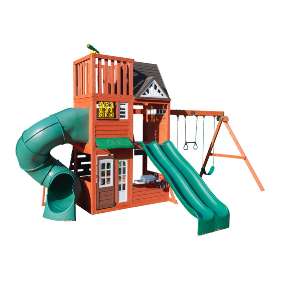
H I L LT O P P L AY S E T F 2 9 0 8 0
INSTALLATION AND OPERATING INSTRUCTIONS
WARNING
OBSTACLE FREE SAFETY ZONE - 32' 11-3/4" x 27' 9-1/2" (10.06 x 8.49 m) area requires Protective Surfacing. See page 3.
MAXIMUM VERTICAL FALL HEIGHT - 7' 8" (2.01 m)
CAPACITY - 15 Users Maximum, Ages 3 to 10; Weight Limit 110 lbs. (49.9 kg) per child.
RESIDENTIAL HOME USE ONLY. Not intended for public areas such as multi-unit residences, schools, churches, nurseries, day cares or parks.
Warning. Only for domestic use.
8.49 m
27' 9-1/2"
3.49 m
11' 5-1/4"
6.06 m
19' 10-1/2"
10 - 12 Hrs
10 - 12 Hrs
14 - 18 Hrs
2-4 Hrs
1 - 2 Hrs
FOR FORT & SWING
FOR FORT & SWING
FOR FORT & SWING
TUBE SLIDE
TWO PERSON
TWO PERSON
For Outdoor Family Domestic Use Only
ASSEMBLY
ASSEMBLY
To reduce the risk of serious injury or death, you must read and follow these instructions. Keep and
refer to these instructions often and give them to any future owner of this play set. Manufacturer
contact information provided below.
10.06 m
32' 11-3/4"
Cedar Summit by KidKraft
4630 Olin Road
Dallas, TX 75244, United States
customersupport@kidkraft . c om
Online Parts Replacement:
Cedarsummitplay . c om/parts-center-warranty-claim
Customer Service:
1(800) 933-0771 or (972) 385-0100
KidKraft Netherlands BV
Olympisch Stadion 8
1076 DE Amsterdam, The Netherlands
Europe Customer Service: +31 (0)20 305 8620
europecustomerservice@kidkraft . c om
EU Online Parts Replacement: parts . k idkraft . e u
Table of Contents
Warnings And Safe Play Instructions . . . . . . . . . . pg . 2
Protective Surfacing Guidelines . . . . . . . . . . . . . . . pg . 3
Instructions For Proper Maintenance . . . . . . . . . pg . 4
About Our Wood – Limited Warranty . . . . . . . . . pg . 5
Keys To Assembly Success . . . . . . . . . . . . . . . . . . . . pg . 6
Part ID . . . . . . . . . . . . . . . . . . . . . . . . . . . . . . . . . . . . . . . pg . 9
Step-By-Step Instructions . . . . . . . . . . . . . . . . . . .pg . 20
Installation of I . D . / Warning Plaque . . . . . .Final Step
9409080
Rev 09/17/2019
Advertisement
Table of Contents

Related Manuals for KidKraft Cedar Summit F29080


Summary of Contents for KidKraft Cedar Summit F29080
- Page 1 For Outdoor Family Domestic Use Only ASSEMBLY ASSEMBLY Cedar Summit by KidKraft 4630 Olin Road Warnings and Safe Play Instructions . . . . . . . . . . pg . 2 Dallas, TX 75244, United States Protective Surfacing Guidelines .
- Page 2 Cool hot slide and rides with water and wipe o l l l i h i l s r fi dry prior to using. run up slide. Orientate slide such that it gets the least amount of exposure to the sun. europecustomerservice@kidkraft.com...
- Page 3 Denotes Use Zone with Protective Surfacing 6 ft. 6 ft. Denotes Use Zone with Protective Surfacing 6 ft. 6 ft. 6 ft. Use Zone for Single-Axis Swings Use Zone for Multi-Axis Swings From the CPSC Outdoor Home Playground Safety Handbook. At http://www.playgroundregs.com/resources/CPSC%20324.pdf europecustomerservice@kidkraft.com...
- Page 4 (See Protective Surfacing, page 3) If you dispose of your play set: Please disassemble and dispose of your unit so that it does not create any unreasonable hazards at the time it is discarded. Be sure to follow your local waste ordinances. europecustomerservice@kidkraft.com...
- Page 5 Such use may lead to product failure and potential injury. Any and all public use will void this warranty. Cedar Summit by KidKraft disclaims all other representations and warranties of any kind, express or implied province to province. This warranty excludes all consequential damages, however, some states do not allow the limitation or exclusion of consequential damages, and therefore this limitation may not apply to you.
- Page 6 5/16” is slightly Washer larger than 1/4”. Note: Wafer head bolts with blue lock Flat tight or a bolt with a Ny-Lok nut do T-Nut Washer NOT require a lock washer. (Hammer into place) Do not crush wood! europecustomerservice@kidkraft.com...
- Page 8 europecustomerservice@kidkraft.com...
- Page 9 1pc. - 9544 - 15.9 x 82.6 x 449.3 - Short Support FSC - Box 3 - 4609544 5/8 x 3 1/4 x 17 11/16" 4pc. - 9545 - 23.8 x 82.6 x 411.2 - Tread FSC - Box 3 - 4609545 15/16 x 3 1/4 x 16 3/16" europecustomerservice@kidkraft.com...
- Page 10 2pc. - 9557 - 31.8 x 76.2 x 838.2 - Fence Post A FSC - Box 3 - 4819557 1 1/4 x 3 x 33" 2pc. - 9558 - 31.8 x 76.2 x 908 - Fence Bottom Narrow FSC - Box 2 - 4819558 1 1/4 x 3 x 35 3/4" europecustomerservice@kidkraft.com...
- Page 11 3pc. - 9571 - 23.8 x 82.6 x 343 - Nest Tread FSC - Box 2 - 4609571 15/16 x 3 1/4 x 13 1/2" 1pc. - 9572 - 15.9 x 76.2 x 374.6 - Stop Behind FSC - Box 3 - 4609572 5/8 x 3 x 14 3/4" europecustomerservice@kidkraft.com...
- Page 12 1pc. - 9068 - 63.5 x 76.2 x 381 - SW Block Angle - Box 3 - 4819068 2 1/2 x 3 x 15" 1pc. - 8507 - 63.5 x 76.2 x 381 - SW Block Angle FSC - Box 3 - 4818507 2 1/2 x 3 x 15" europecustomerservice@kidkraft.com...
- Page 13 Door Window Panel - Box 3 - 47602837 1pc. - 9278 - 38.1 x 316.5 x 718.4 Housetop Skylight Left FSC - Box 2 - 47609278 1 1/4 x 15 3/4 x 42 1/8" 1 1/8 x 12 7/16 x 28 5/16" europecustomerservice@kidkraft.com...
- Page 14 1pc. - 9286 - 90.2 x 1092.2 x 2336.8 9325984 - Playset Hinge - 1pc Front Panel Assembly FSC - Box 3 - 47819286 - 52933505 - Truss Screw #8 x 7/8” - 1pc. 3-1/2 x 43 x 92" - 52933505 9325984 europecustomerservice@kidkraft.com...
- Page 15 9285 - Narrow Back Wall -1pc - 47819285 Back Panel Assembly FSC - Box 2 - 47819287 9325984 - Playset Hinge - 1pc 3-1/2 x 43 x 92" - 52933505 - Truss Screw #8 x 7/8” - 1pc. - 52933505 9325984 europecustomerservice@kidkraft.com...
- Page 16 Part Identification (Reduced Part Size) - TNR3 Extend Flange Rt (3310131) (Green) 1x - Quadrex Driver 1x - Rock Back (9200015) Block (7 Pk) 1x - Rocks (7 Pk) 1x - Kidkraft (3329080) (3330126) 3L ID Plaque Green(9320082LG)/ 1pc. - (9330026) (9320374) Blue(9320082BL)/...
- Page 17 1x - Deluxe Kitchen Set 1x - Hanging Sign (3330008) 1x - Pole Flat Bracket (9331614) (9200286) 1x - BBQ Cook Top Base Assembly (3332609) 1x - BBQ Lid (9327812) 1x - BBQ Base Assembly (3331611) 1x - BBQ Sink Set (3332608) europecustomerservice@kidkraft.com...
- Page 18 Hex Bolt 3/8 x 9-1/4" 1pc. G26 - - (53703891) Hex Bolt 3/8 x 4" 1pc. G20 - - (53703840) 9.5 x 231.8mm 9.5 x 101.6mm Hex Bolt 3/8 x 6" 4pc. G17 - - (53703860) 9.5 x 152.4mm europecustomerservice@kidkraft.com...
- Page 19 #7 x 1-1/8" 8pc. S38 - Pan Screw #12 x 3/4" 48pc. S8 - Pan Screw - (52433603) - (52433014) 50.8mm #12 x 2" 62pc. S7 - Pan Screw - (52433620) #8 x 1-1/8" 6pc. S1 - Wood Screw - (52043514) europecustomerservice@kidkraft.com...
- Page 20 Before you discard your cartons fill out the form below. • The carton I.D. stamp is located on the end of each carton. The tracking number is located on the KidKraft ID Plaque (9320374). • Please retain this information for future reference. You will need this information if you contact the Consumer Relations Department.
- Page 21 Step 2: Access Ladder/Rope Wall Assembly Part 1 A: Place (9054) Left Access on one side of 4 (9545) Treads and (9055) Right Access on the other side with the grooves facing in. (fig. 2.1) B: Fit each (9545) Tread into grooves on both (9054) and (9055) Access rails, make sure the top edge of the (9545) Treads are flush to the front of the Access rails.
- Page 22 Step 2: Access Ladder/Rope Wall Assembly Part 2 D: Place (9544) Short Support on each access rail so there is a 2-3/8” gap between (9544) Short Support and the top (9545) Tread. Attach using 4 (S20) #8 x 1-3/8” Wood Screws. (fig. 2.4, 2.5) 9544 Fig.
- Page 23 S20 X4 Step 2: Access Ladder/Rope Wall Assembly Part 3 E: Place (9058) Rope Rail on the ground next to (9055) Right Access so it matches the orientation of the two access rails as shown in fig. 2.6. Attach (9543) Support Top flush to the top of Access Ladder assembly and (9058) Rope Rail using 3 (S20) #8 x 1-3/8”...
- Page 24 Step 3: Rockwall Assembly A: Place (9546) Access Board Top flush to the top of the Access Ladder/Rockwall Assembly and 1 (9547) Access Board at the bottom of the assembly as shown in fig. 3.1. Measure 2- 3/8” down from the (9546) Access Board Top and place 1 (9547) Access Board.
- Page 25 Step 4: Frame Assembly A: With a helper, stand (9286) Front Panel Assembly and (9287) Back Panel Assembly and unfold each piece at AI-5 the hinges. (fig. 4.1) WL5 X8 B: Place both sections together as shown in fig. 4.1 making sure that they are square. Pre-drill using a 3/16” drill bit and attach panels together at each end using 8 (WL5) 1/4 x 2- 1/2”...
- Page 26 Step 5: Join the Frame Assemblies Part 1 A: Place 1 (9537) Floor Joist along the bottom of the front and back side walls so they are centered over the seams where the panels join together and are flush to the bottom of each panel. Check to make sure the (9537) Floor Joists are level then attach each joist using 4 (S7) #12 x 2”...
- Page 27 AI-7 Step 5: Join the Frame Assemblies WB10 X8(FW2 TN2) Part 2 A: From inside the assembly, halfway up the front side wall, place 1 (9538) Side Joist so that it’s 5/8” below the panels and tight against the end walls . Loosely attach 1 (9538) Side Joist to (9286) Front Panel Assembly and (9287) Back Panel Assembly with 4 (WB10) 5/16 x 2-5/8”...
- Page 28 Step 6: Attach Floor Joist Part 1 A: Place 1 (9540) Floor Board tight to End Slide Panel and 1 (9051) Floor Board tight to SW Wall Panel then attach each to the (9538) Side Joists with 4 (S20) #8 x 1-3/8” Wood Screws per board. (fig. 6.1, 6.2 and 6.3) AI-8 S20 X8 Fig.
- Page 29 Step 6: Attach Floor Joist Part 2 B: Place (9542) Long Floor Joist tight to the bottom of each Floor Board, centered over the pilot holes on the End Slide Panel and SW Wall Panel then attach with 2 (S4) #8 x 3” Wood Screws per panel. Attach (9540) and (9051) Floor Boards to (9542) Long Floor Joist with 2 (S20) #8 x 1-3/8”...
- Page 30 Step 7: Install Brackets Part 1 A: On the inside of the assembly attach the Back Wall Panels using 2 Flat Panel Brackets in the places shown with 4 (S8) #12 x 3/4” Pan Screws per bracket. (fig. 7.1, 7.2 and 7.3) B: Repeat Step A to attach Front Panels.
- Page 31 Step 7: Install Brackets Part 2 C: At all four corners on the bottom and the two top swing wall corners, attach 1 Panel Corner Bracket with 4 (S8) #12 x 3/4” Pan Screws per bracket. (fig. 7.4 & 7.5) AI-10 S8 X24 panel corner bracket X6...
- Page 32 Step 8: Floor Assembly A: Place 1 (9540) Floor Board next to the (9540) Floor Board previously installed. Place the remaining (9051) Floor Boards in the opening making sure that all 15 boards are evenly spaced. Attach using 6 (S20) #8 x 1- 3/8” Wood Screws per board.
- Page 33 Step 9: Attach Wall Top A: From inside the assembly, place (9541) End Wall Top in the opening of SW Wall Panel so that it’s tight to the corners of the panels and the overhang is facing in. Attach using 1 (S11) #8 x 2” Wood Screw at each end as shown in fig.
- Page 34 Step 10: Attach Diagonal A: Loosely attach (2606) SW Ground to (2607) Diagonal with 1 (WB9) 5/16 x 2-1/8” Wafer Bolt (with flat washer and t-nut) then place (2607) Diagonal tight and flush to the front of (9286) Front Panel Assembly. (2606) SW Ground to be flush to the bottom of (9286) Front Panel Assembly.
- Page 35 S20 X4 Step 11: Attach Access Ladder/Rockwall Assembly Part 1 access board must be removed A: Place Access Ladder/Rockwall Assembly from Step 2 against (9287) Back Panel Assembly, flush to the outside edge and flush to the top of the floor boards then attach with 4 (S20) #8 x 1-3/8” Wood Screws. (fig. 11.1) Fig.
- Page 36 Step 11: Attach Access Ladder/Rockwall Assembly Part 2 B: Place (9546) Access Board Top from Step 3, Part 1 against (9055) Right Access and (9058) Rope Rail and flush to the top, Pre drill holes using a 1/8” Drill Bit then attach with 4 (S7) #12 x 2” Pan Screws. (fig. 11.2) Fig.
- Page 37 Step 11: Attach Access Ladder/Rockwall Assembly Part 3 C: Place (9548) Ground Brace so that the angled end is flush to the front and bottom of (9058) Rope Rail and other end is flat against the (9287) Back Wall Assembly. Attach using 4 (S11) #8 x 2” Wood Screws and 1 (S4) #8 AI-15 x 3”...
- Page 38 Step 12: Attach Steel Hand Grips and Handrail to Fort Part 1 A: On the inside edge of (9287) Back Panel Assembly, measure 2” up from the floor and place EN71 Hand Rail so it is flush to the edge as shown in fig. 12.2. The bottom of the Handrail should be centered on (9055) Right Access. Pre-drill holes using a 1/8”...
- Page 39 Step 12: Attach Steel Hand Grips and Handrail to Fort Part 2 B: Measure 6” from the top of (9543) Support Top and on (9287) Back Panel Assembly in the 2 places shown below, pre-drill with a 1/8” drill bit making sure holes are centred then attach 2 Steel Hand Grips with 2 (WL3) 1/4 x 1-3/8”...
- Page 40 Step 13: Door Panel Assembly Part 1 A: On the inside of (2837) Door Window Panel measure 15” up from the bottom and attach Catch Plate flush to the edge using 2 (S38) #7 x 1-1/8” Pan Screws. (fig. 13.1 and 13.2) B: On the inside of (2837) Door Window Panel measure 22”...
- Page 41 Step 13: Door Panel Assembly Part 2 C: On the outside of the (2837) Door Window Panel attach the second Door Handle at approximately the same place as the one on the inside. Use 2 (S37) #7 x 5/8” Pan Screws. (fig. 13.3) S38 X2 D: Attach 2 Door Hinges on the outside of the (2837) Door Window Panel on the opposite side from the Door S37 X2...
- Page 42 Step 13: Door Panel Assembly Part 3 AI-19 E: In the opening for the door, measure 3/4” from the top of (9286) Front Panel Assembly and maximum 5/8” from S37 X6 right side of the opening which would be the Door Hinge side and attach the remaining side of the hinges to (9286) AI-19 Front Panel Assembly using 3 (S37) #7 x 5/8”...
- Page 43 Step 13: Door Panel Assembly Part 4 F: In the notched out opening of (2715) Door Stop attach the Magnetic Catch using 2 (S38) #7 x 1-1/8” Pan Screws. (fig. 13.8) Important: Use a hand held screw driver and DO NOT over tighten. G: On the inside of the assembly, attach (2715) Door Stop to (9286) Front Panel Assembly with 3 (S11) #8 x 2”...
- Page 44 Step 14: Front Wall Assembly Part 1 A: Place (9539) Table Support flush to the notched of (2611) Table Top and attach with 4 (S7) #12 x 2” Pan Screws as shown in fig. 14.1. B: Place Table Top Assembly in the center of opening and tight to (9286) Front Panel Assembly and attach (9539) Table Support to (9286) Front Panel Assembly with 2 (S3) #8 x 2-1/2”...
- Page 45 Step 14: Front Wall Assembly Part 2 C: From the inside of the assembly attach (2611) Table Top to slats in (9286) Front Panel Assembly with 2 Flat Brackets using 3 (S37) #7 x 5/8” Pan Screws per bracket. (fig. 14.4, 14.5) Fig.
- Page 46 Step 15: Attach MOD SIDE Lite AI-22 Part 1 S0 X14 D: From inside the assembly place MOD Side Lite into window opening in (9286) Front Panel Assembly as shown in fig. 15.1. Attach using 14 (S0) #8 x 7/8” Truss Screws.(Fig. 15.1 & 15.2) Fig.
- Page 47 Step 15: Attach MOD SIDE Lite Part 2 E: From inside the assembly, place MOD4 Side Lite in the small upper opening and attach using 10 (S0) #8 x 7/8” AI-27 Truss Screws. (Fig. 15.3 & 15.4) S0 X10 Fig. 15.4 Inside View AI-27 S0 X10...
- Page 48 Step 16: Tic Tac Toe Assembly Part 1 A: Center the top of Tic Tac Toe assembly in the upper opening of the (9286) Front Panel Assembly so that it’s flush to the inner edge. Attach using 3 (S0) #8 x 7/8” Truss Screws. (fig. 16.1) B: Center Tic Toe Bottom on the inside edge of (9579) Playroom Bottom checking to make sure that it lines up with the Tic Tac Toe top piece.
- Page 49 Step 16: Tic Tac Toe Assembly Part 2 D: From outside the assembly, angle the Tic Tac Toe Assembly so that the three rows fit into the Tic Tac Toe assembly top and so (9579) Playroom Bottom fits into the bottom of the opening. (fig.16.3) E: Attach (9579) Playroom Bottom to (9286) Front Panel Assembly using 2 (S11) #8 x 2”...
- Page 50 (171) Engineered SW Beam as shown in fig. 17.1 and 17.4. IT IS IMPORTANT THAT THIS BOLT IS ATTACHED. IT WILL MINIMIZE CHECKING OF WOOD. D: Attach Cedar Summit by KidKraft Plaque to centre of (9049) Engineered SW Beam (over top of t-nut) using 4 (S38) #7 x 1-1/8” Pan Screws. (fig. 17.5) 9049 Fig.
- Page 51 Step 17: Swing Beam Assembly Part 2 E: On the Fort End of (9049) Engineered SW Beam attach 2 Heavy Flat Brackets with 2 (G21) 5/16 x 3-3/4” Hex Bolts (with 2 flat washers and 1 lock nut). (fig. 17.6 and 17.7) F: Place (9069) SW Mount in between both Heavy Flat Brackets and place 1 Heavy L-Bracket against (9049) Engineered SW Beam and (9069) SW Mount.
- Page 52 Step 18: Swing Post Assembly Part 1 Heavy L-Bracket Note: Keep all bolts from Step 18 series loose Fig. 18.1 until start of Step 20 Bottom View A: Place (9068) SW Block Angle on top of (8507) Block SW and attach 2 Heavy L-Brackets on top of 8507 (9068) SW Block Angle feeding 2 (G17) 3/8 x 6”...
- Page 53 Step 18: Swing Post Assembly Part 2 D: Place Swing End of (9049) Engineered SW Beam in between Heavy L-Brackets assembled in Step A making sure holes are lined up then attach Swing Post Assembly to Swing Beam Assembly using 1 (G20) 3/8 x 4”...
- Page 54 Step 18: Swing Post Assembly Part 3 F: Place (9069) SW Mount flush to the top of SW Wall Panel. Attach with 1 (G5) 5/16 x 4-1/2” Hex Bolt (with lock washer, flat washer and t-nut) in the bottom hole from outside the assembly and 1 (G5) 5/16 x 4-1/2” Hex Bolt (with 2 x flat washer and 1 lock nut) in the top hole from inside the assembly.
- Page 55 Step 19: Attach Cross Support Pre-drill all holes using a 3/16” drill bit before installing the lag screws. Fig. 19.1 A: To adjust for uneven ground, raise or lower the (9067) Support Cross on the (9070) SW Post. Make sure the Support Cross is level prior to attaching with the lag screws.
- Page 56 Step 20: Final Swing Post Assembly Pre-drill all holes using a 3/16” drill bit before installing the lag screws. Note: Tighten all bolts from Step 18 series before installing lag screws. A: Attach 1 (LS9) 5/16 x 4-3/4” Lag Screw (with flat washer) into each (9070) SW Post, as shown in fig. 20.1. B: Attach 1 (LS9) 5/16 x 4-3/4”...
- Page 57 Step 21: Install Ground Stakes MOVE FORT TO FINAL LOCATION PRIOR TO STAKING FINAL LOCATION MUST BE LEVEL GROUND A: In the 5 places shown in fig. 21.1 drive the Rebar Ground Stakes 13” into the ground against both (2606) SW Ground, (9287) Back Panel Assembly and both (9070) SW Post.
- Page 58 Step 22: Attach Cross Frame Part 1 Note hole orientation for this step. A: Tight to the floor boards and tight in each corner of (9287) Back Panel Assembly end wall, attach 2 (9553) Supports to (9286) Front Panel Assembly and (9287) Back Panel Assembly with 5 (S3) #8 x 2-1/2” Wood Screws per support.
- Page 59 Step 22: Attach Cross Frame Part 2 A: Place (9581) Cross Frame across the opening in the end panel as shown in fig. 22.2. Attach each end of the board to the (9553) Supports using 2 (S3) #8 x 2- 1/2” Wood Screws. 9553 Fig.
- Page 60 Step 23: Attach Terrace Assembly Part 1 A: Place (9561) Terrace Support Right and (9560) Terrace Support Left on either side of (9562) Mid Joist, taking note of the hole orientation. Line (9562) Mid Joist up with the pre-drilled holes in each Terrace Support and attach using 2 (S3) #8 x 2 -1/2”...
- Page 61 AI-30 S4 X4 Step 23: Attach Terrace Assembly Part 2 E: Place (9563) Deck Floor Support between (9562) Mid Joist and the end wall of (9287) Back Panel Assembly so that it is centered over the pilot holes as shown in fig. 23.4. Attach using 2 (S4) #8 x 3” Wood Screws per side.(Fig. 23.4 &...
- Page 62 Step 23: Attach Terrace Assembly Part 3 F: Place (9564) Terrace Floor Board so that it’s tight to the (9553) Supports and attach using 6 (S20) #8 x 1- 3/8” Wood Screws. (Fig 23.6 & 23.7) G: Place 1 (9051) Floor Board at the opposite end making sure that it’s flush to the edge of (9562) Mid Joist and attach using 6 (S20) #8 x 1- 3/8”...
- Page 63 Step 24: Attach Fence Assembly Part 1 A: Place 2 (9558) Fence Bottom Narrows one above the other with the notched out ends facing up. Fit 1 (9556) Fence Post into the notches at each end of the (9558) Fence Bottom Narrows and attach using 2 (WB2) 5/16 x 1- 3/8”...
- Page 64 Step 24: Attach Fence Assembly Part 2 C: Place 2 (9555) Bottom Fence boards one above the other with the notched out ends facing up. Fit 1 (9556) Fence Post into the notches on the right side of the (9558) Fence Bottom Narrows 1 (9557) Fence Post A on the left side and attach using 2 (WB2) 5/16 x 1- 3/8”...
- Page 65 Step 24: Attach Fence Assembly Part 3 E: Place 2 (9555) Bottom Fence boards one above the other with the notched out ends facing up. Fit 1 (9557) Fence Post A into the notches on the right side of the (9558) Fence Bottom Narrows 1 (9556) Fence Post on the left side and attach using 2 (WB2) 5/16 x 1- 3/8”...
- Page 66 Step 24: Attach Fence Assembly Part 4 G: Bring the fence panel assemblies together as shown in fig. 24.4, making sure that the panel configuration is correct and that the panels are flush at the bottom corners. Check to make sure that the assembly is square and pre-drill using a 3/16”...
- Page 67 Step 25: Attach Fence to Fort A: With a helper, lift the fence assembly onto the open end of the fort so that the (9553) Supports are positioned AI-34 on the inside corners of the fence assembly. Attach fence assembly to the (9553) Supports from the outside using S20 X32 2 (H11) 1/4”...
- Page 68 Step 26: Nest Ladder Assembly Part 1 A: Place (9570) Nest Left Access on one side of 3 (9571) Nest Treads and (9569) Nest Right Access on the other side with the grooves facing in. (fig. 26.1 & 26.2) B: Fit each (9571) Nest Tread into grooves on both ( 9569) and (9570) Nest Access Rails, making sure the top edge of the ( 9571) Nest Treads are flush to the front of the Access rails.
- Page 69 Step 26: Nest Ladder Assembly Part 2 E: Place Nest Ladder in the second level of the Clubhouse so that it’s centered and the top of the ladder is leaning flat against the (9562) Mid Joist. (Fig. 26.4) F: Check to ensure that the Nest Ladder is flush to the top of the Floor Boards then pre-drill using a 1/8” drill bit. Attach Nest Ladder using 1 (WB8) 5/16 x 2-3/8”...
- Page 70 Step 26: Nest Ladder Assembly Part 3 G: Place 1 Corner Bracket on the bottom outside edge of (9570) Nest Left Access so that it’s flush to the front of the ladder and the straight edge of the bracket is on the floor board. Attach using 3 (S37) #7 x 5/8” Pan Screw.(fig. 26.5 &26.6) AI-47 S37 X3...
- Page 71 Step 27: Roof Assembly Part 1 A: Making sure that the sharper angles are at the top, place (9551) Roof Support Left and (9552) Roof Support Right together so they form a peak. Attach using 1 (S3) #8 x 2- 1/2” Wood Screw. (fig. 27.1) B: Repeat Step A to create a second Roof Support Assembly.
- Page 72 Step 27: Roof Assembly Part 2 C: With a helper, hold (9276) Back Roof and (9277) Front Roof in position so that they are flush at the roof peak and line up with the roof support assemblies. D: Making sure that the roof support assemblies are flush to the bottom of the roof panels, attach each roof support assembly to each end of the roof panels using 8 (S11) #8 x 2”...
- Page 73 Step 27: Roof Assembly Part 3 E: Secure (9277) Front Roof to (9276) Back Roof at the top of the assembly using 4 (S11) #8 x 2” Wood Screws. (fig. 27.3) AI-41 S11 X4 Fig. 27.3 9276 9277 Hardware #8 x 2” Wood Screw...
- Page 74 Step 27: Roof Assembly Part 4 AI-42 S0 X? F: From inside the roof assembly, place 1 Small Triangle Window into the top right corner and attach using 6 (S0) #8 x 7/8” Truss Screws. (fig. 27.4 & 27.5) AI-42 S0 X? Fig.
- Page 75 Step 28: Big Triangle Window Assembly Part 1 A: Place (9278) Housetop Skylight Left and (9279) Housetop Skylight Right together so they form a peak. Fit (9565) Skylight Bottom in place under the panels so that it’s flush to the corners. B: Attach (9565) Skylight Bottom to each skylight panel using 1 (S11) #8 x 2”...
- Page 76 Step 28: Big Triangle Window Assembly Part 2 C: From the underside of the skylight assembly, place 1 New Big Triangle Window into the frame. Make sure (9278) Housetop Skylight Left and (9279) Housetop Skylight Right are tight together, then attach New Big Triangle Window using 9 (S0) #8 x 7/8”...
- Page 77 Step 28: Big Triangle Window Assembly Part 3 E: Attach (9278) Housetop Skylight Left to (9279) Housetop Skylight Right at the top corner using 1 (S11) #8 x 2” Wood Screw. (fig. 28.6) AI-40 S11 X1 Fig. 28.6 9278 9279 Hardware #8 x 2”...
- Page 78 Step 29: Attach Big Triangle Window to Roof Assembly A: With a helper, fit the Small Triangle Window Assembly into the opening of the Roof Assembly as shown in figs 29.1 and 29.2. Attach from the inside using 4 (S3) #8 x 2- 1/2” Wood Screws. Fig.
- Page 79 Step 30: Attach Soffits A: Taking care to note the hole orientation, place 1 (9549) Roof Base along the top of the front wall panel so that it’s flush with the inside of the wall. Attach using 4 (S20) #8 x 1- 3/8” Wood Screws. (fig. 30.1) B: Place (9550) Narrow Roof Base along the end panel making sure that it’s flush to (9549) Roof Base.
- Page 80 Step 31: Attach Roof to Fort A: With one person in the assembly and at least one helper on the ground, lift the roof assembly onto the roof base so that the Small Triangle Window is facing the front. (fig. 31.1 & 31.2) B: Attach from the underside of the roof base using 5 (S20) #8 x 1-3/8”...
- Page 81 AI-46 Step 32: Attach Roof Tie S4 X6 A: On each side of the roof assembly, place a (9559) Roof Tie so that they are resting flush on the Roof Supports and are flush to the outside edges of the (9556) Fence Posts. Attach (9559) Roof Ties to the (9556) Fence Posts and to the Roof Supports using 3 (S4) #8 x 3”...
- Page 82 AI-48 S4 X2 Step 33: Attach Roof Support AI-48 S4 X2 A: From inside the assembly attach Roof Assembly to (9556) Fence Posts using 1 (S3) #8 x 2 1/2” Wood Screw per side. (fig. 33.1 & 33.2 & 33.3) Fig.
- Page 83 Step 34: Attach Fence Board A: From inside the upper deck, position a (9567) Fence Board Long A on each side of the Roof Assembly, making sure that the boards are flush to the top of (9559) Roof Tie. Attach each board using 1 (H2) 1/4 x 2” Hex Bolt (with flat washer, lock washer and t-nut) in the top hole and 2 (S20) #8 x 1- 3/8”...
- Page 84 Step 35: Attach Roof Pull Part 1 A: Position (9578) Rope Pull between the 2 (9567) Fence Board Long A’s making sure that it’s flush to the top of (9559) Roof Tie. Attach using 8 (S20) #8 x 1- 3/8” Wood Screws. (fig. 35.1) AI-49 S20 X8 Fig.
- Page 85 Step 36: Slide Opening Assembly A: Position 2 (9575) Slide Posts so the notches are facing up, with the smaller notches are the bottom. Place (9573) Slide Bottom into the smaller bottom notches and attach using 1 (WB2) 5/16 x 1- 3/8” Wafer Head Bolt (with flat washer and t-nut) per side.
- Page 86 Step 37: Attach Slide Opening Assembly to Fort Part 1 A: Place the Slide Entrance Assembly into the opening in the slide end panel and attach using 11 (S24) #10 x 4” Wood Screws in the bottom and sides of the assembly. (Fig. 37.1) AI-51 S24 X11 Fig.
- Page 87 Step 37: Attach Slide Opening Assembly to Fort Part 2 B: From inside the assembly, place a Flat Panel Bracket at the top end of the Slide Entrance Assembly so that the brackets are centered over the (9574) Slide Top, (9575) Slide Posts and (9287) Back Panel Assembly. Attach each bracket using 4 (S8) #12 x 3/4”...
- Page 88 Step 38: Slide Section Assemblies Part 1 Note: When installing Pan Bolts make sure to look at holes so bolts go through the side with the round recess and the lock nuts go through the side with the hexagonal recess. (Fig. 3.3). A: Fit 2 TNR2 Slide Elbows together and attach with 8 (PB1) 1/4 x 3/4”...
- Page 89 Step 38: Slide Section Assemblies Part 2 Note: When installing Pan Bolts make sure to look at holes so bolts go through the side with the round recess and the lock nuts go through the side with the hexagonal recess. (fig. 38.3) D: Attach TNR2 Slide Exit Top and the remaining TNR2 Slide Elbow together using 8 (PB1) 1/4 x 3/4”...
- Page 90 Step 39: Attach Flange Assembly to Fort Part 1 A: With a helper place the Flange Assembly flush to the slide entrance assembly as shown in fig. 39.1, then pre-drill 1/8” pilot holes in (9574) Slide Top for the 4 upper mounting locations (approximate spots where circles are on figure), making sure the pre-drilled holes are a minimum of 1”...
- Page 91 Step 39: Attach Flange Assembly to Fort Part 2 D: Place (9576) Gusset centred and tight to Slide End Panel and attach to Flange Assembly with 2 (S6) #12 x 1” Pan Screws. (fig. 39.4 & 39.5) E: Pre-drill pilot hole with a 3/16” drill bit then attach (9576) Gusset to Slide End Panel with 1 (WL5) 1/4 x 2-1/2” Wafer Lag (with flat washer).
- Page 92 Step 40: Attach Elbow Assembly to Flange Assembly Note: Keep all bolts loose until further step. A: Fit one of the Elbow Assemblies to the Flange Assembly by lining up the arrows on each assembly. Attach Elbow Assembly to Flange Assembly using 6 (PB1) ¼ x 3/4” Pan Bolts and Square Lock Nut. (fig. 40.1, 40.2 and 40.3) B: Attach one of the Elbow assemblies to another Elbow Assembly making sure to line up the arrows on each assembly.
- Page 93 Step 41: Attach TNR 3 Slide Exit to Elbow Assembly A: Insert flange of Exit Elbow Assembly (slide elbow) into the slots on TNR3 Short Exit. (fig. 41.1) B: Rotate Slide Exit and use Quadrex Driver as a guide pin so the holes are aligned and attach with 5 (PB1) 1/4 x 3/4”...
- Page 94 Step 42: Attach Exit End Assembly to Fort A: Fit the Exit End Assembly to the last Elbow Assembly by lining up the arrows on each assembly. Notice the elbow orientation. (fig. 42.1). Attach with 6 (¼ x 12.7)mm Pan Bolts and Square Lock Nuts. (fig. 42.2) AI-56 Fig.
- Page 95 Step 43: Attach TNR 4 Clamp Rings A: Place 2 TNR4 Clamp Rings around each joint making sure to match the arrows with the end of the Clamp Ring as shown in (fig. 43.1 & 43.2 ). B: Connect TNR4 Clamp Rings in 2 spots using 1 (PB6) ¼ x 1” Pan Bolt (with lock nut) per side. (fig. 43.3) Note: When installing Pan Bolts make sure to look at holes so bolts go through the side with the round recess and the lock nuts go through the side with the hexagonal recess.
- Page 96 Step 44: Attach TNR 3 Slide to Fort A: On the fourth attached Elbow Assembly remove the pan bolt and nut which is facing the fort (installed in Step 38). (fig. 44.1) The bolt will no longer be needed, but keep the lock nut. B: Loosely attach TNR3 Tube Support (at the slightly bent end) to the slide seam using 1 (PB6) 1/4 x 1”...
- Page 97 Step 45: TNR Brace Assembly A: Attach (9680) TNR Upright to (9577) TNR Ground Brace with 1 (H8) 1/4 x 4-1/4” Hex Bolt (with lock washer, flat washer and t-nut) in the top hole. Make sure both boards are square then attach with 1 (S4) #8 x 3” Wood Screw.
- Page 98 Step 46: Attach Elbow Assemblies and TNR4 Slide A: Attach (9577) TNR Ground Brace to (9548) Ground Brace using with 2 (S4) #8 x 3” Wood Screws. (fig. 46.1). B: Place 1 TNR4 Post Mount Clamp on either side of the Clamp Ring so that the bent tops clip in behind the Clamp Ring.
- Page 99 Step 47: Attach Ground Stake to TNR Upright A: In the spot shown in fig. 47.1 drive 1 Rebar Ground Stake 13” into the ground against the (9577) TNR Ground Brace. Be careful not to hit the washer while hammering stake into the ground as this could cause the washer to break off.
- Page 100 Step 48: Attach Swings A: Using 1 Threaded Quick Link per chain, join 1 Long Swing Chain to each side of the Swing Belt Seat. Make sure to close the Threaded Quick Link tightly using an adjustable wrench. (fig. 48.1 and 48.2). B: Using 1 Threaded Quick Link per chain, join the Short Swing Chain to the Acro Bar and Acro Handle.
- Page 101 Step 49: Assemble and Attach BBQ Kitchen Part 1 A: On (9286) Front Wall place BBQ Base on (2611) Table Top. Use BBQ Cooktop as a guide so there is enough room for BBQ Cooktop and 1” gap to the edge of the wall to the left of BBQ Base. Attach BBQ Base to (2611) Table Top with 4 (S0) #8 x 7/8”...
- Page 102 Step 49: Assemble and Attach BBQ Kitchen Part 2 C: Slide BBQ Cooktop tight beside BBQ Base on the left and BBQ Sink Set tight on the right. Attach both BBQ Cooktop and BBQ Sink Set to (2611) Tabel Top with 2 (S0) #8 x 7/8” Truss Screws each. (fig.49.5, 49.6, 49.7 and 49.8) D: Place Faucet and 2 Sink Knobs in opening of Sink and attach Sink Knobs with included hardware.
- Page 103 Step 50: Attach Utensil Shelves Part 1 A: From outside the assembly in the top left side of the opening in (1986) Front Panel Assembly, 1” in from the panel, attach 1 Utensil Shelf with 2 (S0) #8 x 7/8” Truss Screws as shown in fig. 50.1 and 50.2. B: Attach Sign to the Utensil Shelf.(Fig.
- Page 104 Step 50: Attach Utensil Shelves Part 2 D: From outside the assembly, centred below the BBQ Kitchen attach 1 Utensil Shelf to (2611) Table Top with 2 (S0) #8 x 7/8” Truss Screws as shown in fig. 50.4 and 50.5. E: Attach Pan, Tongs and Spatula to the Utensil Shelf.
- Page 105 Step 51: Attach Slides to Fort Note: Pre-drill all holes using a 1/8” drill bit before installing the pan screws. A: Place Slide centred in the opening of the (9286) Front Wall Panel. (fig. 51.1) B: Attach slide to fort using 4 (S7) #12 x 2” Pan Screws. (fig. 51.2) AI-63 S7 X4 AI-63...
- Page 106 Step 52: Attach Pole Part 1 AI-60 A: Attach Fire Man Pole to (9580) Pipe Top using 3 (H9) 1/4 x 1- 1/4” Hex Bolts (with lock washer, flat washer H9 X3(FW1 TN1) and t-nut). (fig. 52.1) Fig.52.1 1/4” T-Nut 1/4”...
- Page 107 Step 52: Attach Pole Part 2 B: In the upper left side opening in the (9287) Back Panel Assembly, position (9580) Pipe Top against the frame from the outside, making sure the Fire Man Pole is straight and that the bottom of the pole is on the ground. Pre- drill using a 1/8”...
- Page 108 Step 53: Attach U-Style Ground Stake to Pole A: Check to ensure that the pole is 2- 1/2” into the ground and plate is lying flat. Hammer U-Style Ground Stakes into the holes in the plate until they are fully anchored into the ground. (Fig.53.1) Fig.
- Page 109 Step 54: Attach Telescope A: On the top left hand corner of the upper Fence, attach Telescope Base on an angle with 2 (S20) #8 x 1-3/8” Wood Screw. (fig. 54.1 & 54.2) AI-61 S20 X2 Fig. 54.1 Telescope Fig. 54.2 Hardware Other Parts 1 x Telescope...
- Page 110 S5 X2 Step 55: Attach Canopy A: Feed Cafe Canopy Frame through the pocket of the Cafe Canopy. (fig. 55.1) B: With a helper hold the Canopy against the fort, centered over the door and window on (9286) Front Panel As- sembly (fig.
- Page 111 Step 56: Attach Rocks A: From behind the Rock Wall, place 1 Rock Back Block between the boards and hold in place. On the front of the wall, place 1 Rock over the Rock Back Block and install 2 (PB3) 1/4 x 1- 3/4” Pan Bolts (with lock washer, 3/16” flat washer and lock nut) through the Rock and the Rock Back Block as shown in figs.
- Page 112 Final Step: Attach I.D. Plaque ATTACH THIS WARNING & I.D. PLAQUE TO THIS LOCATION ON YOUR PLAY EQUIPMENT! This provides warnings concerning safety and important contact information. A Tracking Number is provided to allow you to get critical information or order replacement parts for this specific model. A: Attach KK Playset Plaque to a location on your set that is easily...
- Page 113 NOTES europecustomerservice@kidkraft.com...
- Page 114 NOTES europecustomerservice@kidkraft.com...
- Page 115 NOTES europecustomerservice@kidkraft.com...
- Page 116 Would you recommend the purchase of our products to friends and family? Comments: MAIL TO: Fill out your registration card online at KidKraft www.cedarsummitplay.com/ 4630 Olin Road registration Dallas, TX 75244 United States Cedar Summit by KidKraft would like to say Attention: Customer Service Thank You for your time and feedback.
Need help?
Do you have a question about the Cedar Summit F29080 and is the answer not in the manual?
Questions and answers
Cannot find Batch Code on Hilltop Playset F29080
The batch code is located on the KidKraft ID Plaque (9320374) of the KidKraft Cedar Summit F29080 Hilltop Playset.
This answer is automatically generated
Buenas tardes quisiera saber cuánto tipo tardan entre 2 personas en armar la casa de juegos