Table of Contents
Advertisement
M C K I N L E Y - F 2 4 9 5 0
INSTALLATION AND OPERATING INSTRUCTIONS
WARNING
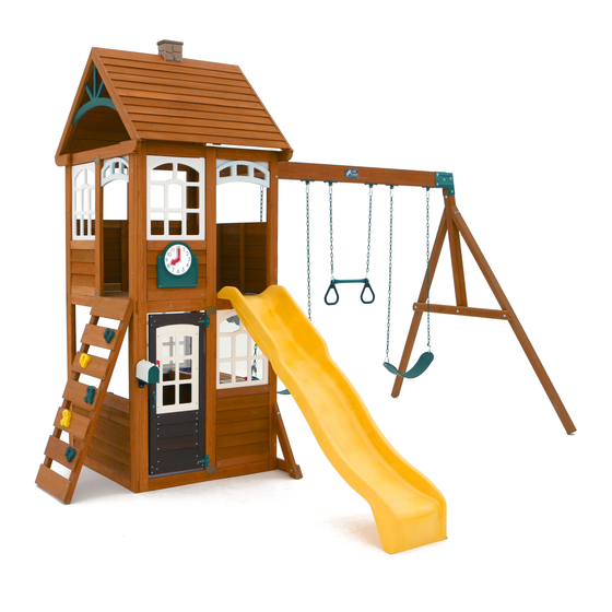
OBSTACLE FREE SAFETY ZONE - 26'-3" x 28' area requires Protective Surfacing. See page 3.
MAXIMUM VERTICAL FALL HEIGHT - 6'9"
CAPACITY - 9 Users Maximum, Ages 3 to 10; Weight Limit 110 lbs. (49.9 kg) per child.
RESIDENTIAL HOME USE ONLY. Not intended for public areas such as schools, churches, nurseries, day cares or parks.
Warning. Only for demestic use.
26'- 3"
14'- 3"
FORTS
10-14 Hrs
Two person
assembly
KidKraft, Inc.
4630 Olin Road
Dallas, Texas 75244 USA
customerservice@kidkraft.com
canadacustomerservice@kidkraft.com
1.800.933.0771
972.385.0100
For online parts replacement visit
https://parts.kidkraft.com/
To reduce the risk of serious injury or death, you must read and follow these instructions. Keep
and refer to these instructions often and give them to any future owner of this play system.
Manufacturer contact information provided below.
11'-5"
28'-0"
McKinley
FOR OUTDOOR FAMILY DOMESTIC USE ONLY
KidKraft Netherlands BV
Olympisch Stadion 8
1076 DE Amsterdam
The Netherlands
europecustomerservice@kidkraft.com
+31 20 305 8620 M-F from 09:00 to 17:30
(GMT+1)
For online parts replacement visit
https://parts.kidkraft.eu/
Table of Contents
Warnings and Safe Play Instructions. . . . . . . . . . pg. 2
Protective Surfacing Guidelines . . . . . . . . . . . . . . . pg. 3
Instructions for Proper Maintenance . . . . . . . . . pg. 4
About Our Wood - Limited Warranty . . . . . . . pg. 5-6
Keys to Assembly Success . . . . . . . . . . . . . . . . . . . . pg. 7
Metric Conversion Sheets . . . . . . . . . . . . . . . . . . . . pg. 8
Part ID . . . . . . . . . . . . . . . . . . . . . . . . . . . . . . . . . . . . . . .pg. 10
Installation of I.D./Warning Plaque . . . . . . . . . .pg. 60
Fort Guides . . . . . . . . . . . . . . . . . . . . . . . . . . . . . . pg. 61-62
9414950
Rev 11/23/2020
Advertisement
Table of Contents

Related Manuals for KidKraft MCKINLEY F24950


Summary of Contents for KidKraft MCKINLEY F24950
-
Page 1: Table Of Contents
About Our Wood – Limited Warranty ..pg. 5-6 KidKraft, Inc. KidKraft Netherlands BV Keys to Assembly Success ....pg. 7... -
Page 2: Warnings And Safe Play Instructions
Warnings and Safe Play Instructions CONTINUOUS ADULT SUPERVISION REQUIRED. Most serious injuries and deaths on playground equipment have occurred while children were unsupervised! Our products are designed to meet mandatory and voluntary safety standards. Complying with all warnings and recommendations in these instructions will reduce the risk of serious or fatal injury to children using this play system. -
Page 3: Protective Surfacing Guidelines
Protective Surfacing - Reducing Risk of Serious Head Injury From Falls One of the most important things you can do to reduce the likelihood of serious head injuries is to install shock-absorbing protective surfacing under and around your play equipment. The protective surfacing should be applied to a depth that is suitable for the equipment height in accordance with ASTM F1292. -
Page 4: Instructions For Proper Maintenance
Instructions for Proper Maintenance Your KidKraft Play System is designed and constructed of quality materials with your child’s safety in mind. As with all outdoor products used by children, it will weather and wear. To maximize the enjoyment, safety and life of your Play Set, it is important that you, the owner, properly maintain it. -
Page 5: About Our Wood - Limited Warranty
About Our Wood KidKraft Premium Play Systems uses only premium playset lumber, ensuring the safest product for your children’s use. Although we take great care in selecting the best quality lumber available, wood is still a product of nature and susceptible to weathering which can change the appearance of your set. - Page 6 KidKraft Limited Warranty MISSING OR DAMAGED PARTS: KidKraft will replace any parts within 90 days from date of purchase found to be missing from or damaged in the original packaging. See Fig.1 Fig. 1 Product Age (All Parts) Consumer Pays...
-
Page 7: Keys To Assembly Success
Keys to Assembly Success Tools Required • Tape Measure • #1 Phillips, #2 Robertson • Open End Wrench • 3/16”(5mm) Hex Key • Carpenters Level and Screwdriver 1/2” (13mm) & 9/16”(14 mm) • 8’ (2.4m) Step Ladder • Carpenters Square •... -
Page 10: Part Id
Part Identification (Reduced Part Size) Part Identification (Reduced Part Size) Part Identification (Reduced Part Size) Part Identification (Reduced Part Size) 2pc. - 2717 - Clock Block 3/4 x 1-3/4 x 9-3/4" Nominal Size Actual Size 5/4 x 5 15/16 x 4-1/4 Box 2 - 3632717 5/4 x 6 15/16 x 5-1/4... - Page 11 Part Identification (Reduced Part Size) 2pc. - 2618 Front Back 1pc. - 2627 1pc. - 2639 Panel 1¼ x 42 x 87" SW Wall Panel 1¼ x 42 x 87" Back Roof Panel 1¼ x 36¾ x 44" Box 2 - 37632618 Box 2 - 37632627 Box 2 - 37632639 1pc.
- Page 12 Hardware Identification (Actual Size) 10pc. TN1 - 1/4" T - Nut 5pc. FW0 - 3/16" Flat Washer - (51103100) 5pc. LW2 - 5/16" Lock Washer - (51303300) (54503200) 12pc. FW1 - 1/4" Flat Washer - (51103200) 8pc. TN2 - 5/16" T- Nut (54503300) 15pc.
- Page 13 Hardware Identification (Actual Size) 1/4 x 2-1/2" 16pc. WL5 - Wafer Lag Wafer Bolt 5/16 x 3" 3pc. WB7 - - (53613330) - (52613222) Hex Bolt 1/4 x 2-3/4" 4pc. H11 - - (53703223) Hex Bolt 1/4 x 2-1/4" 2pc. H10 - - (53703221) Hex Bolt 5/16 x 3-3/4"...
- Page 14 1x - Clock Subset (3320329 ) 1x - Rebar Ground Stake (6 Pk) (3200318) 1x - Rocks (5pk) (3320386) 1x- Kidkraft Logo Plaque 2x - Jamb Mount (3320353) (9206300) 1x - Welded Chain Bag (3200170) Green 4x 9201254 54" chain -Green 2x 9201225 25"...
- Page 15 If there are any missing or damaged pieces or you need assistance with assembly please contact the consumer relations department directly. Call us before going back to the store. 1.800.933.0771 or 972.385.0100 +31 20 305 8620 customerservice@kidkraft.com europecustomerservice@KidKraft.com canadacustomerservice@kidkraft.com For online parts replacement visit For online parts replacement visit https://parts.kidkraft.eu/...
- Page 16 Step 2: Frame Assembly Part 1 It is important to assemble the frame on a flat, smooth surface. A: Place (2627) SW Wall Panel between 2 (2618) Front Back Panels noticing the panel orientations. The tops and bottoms of the panels should be flush. Make sure the panels are square then using the pilot holes as a guide pre-drill with a 3/16”...
- Page 17 Step 2: Frame Assembly Part 2 B: Place (2622) End Panel Assembly between both (2618) Front Back Panels noticing the panel orientations. The tops and bottoms of the panels should be flush. Make sure the panels are square then using the pilot holes as a guide pre-drill with a 3/16”...
- Page 18 Step 3: Floor Assembly Part 1 A: From inside the assembly centre (2608) Floor Joist over pilot holes in (2622) End Panel Assembly and (2627) SW Wall Panel, 5/8” down from the top of board then attach (2608) Floor Joist to each panel with 2 (S4) #8 x 3” Wood Screws per end.
- Page 19 Step 3: Floor Assembly Part 2 B: On both (2618) Front Back Panels attach 1 (2610) Side Joist to the inside of each panel with 2 (H11) 1/4 x 2-3/4” Hex Bolts (with lock washer, flat washer and t-nut) and 4 (S3) #8 x 2-1/2” Wood Screws as shown in fig. 3.4 and 3.5.
- Page 20 Step 3: Floor Assembly Part 3 C: Starting at (2627) SW Wall Panel place (2648) Floor Board followed by 8 (2609) Floor Boards. Make sure all boards are evenly spaced then attach to (2608) Floor Joist and each (2610) Side Joist with 5 (S20) #8 x 1-3/8” Wood Screws per board.
- Page 21 Step 4: Attach SW Ground and Diagonal A: Loosely attach 1 (2606) SW Ground to each (2607) Diagonal with 1 (H10) 1/4 x 2-1/4” Hex Bolt (with lock washer, flat washer and t-nut) per board then place each (2607) Diagonal tight and flush to the front of (2627) SW Wall Panel.
- Page 22 Beam as shown in fig. 5.3. IT IS IMPORTANT THAT THIS BOLT IS ATTACHED. IT WILL MINIMIZE CHECKING OF WOOD. D: Attach KidKraft Plaque to centre of (2614) Engineered Beam (over top of t-nut) using 4 (S18) #6 x 1” Wood Screws. (fig. 5.4)
- Page 23 Step 6: Swing End Assembly A: Loosely attach 2 (2613) Heavy SW Posts to (2615) SW Upright using 2 (G7) 5/16 x 5-1/2” Hex Bolts (with lock washer, flat washer and t-nut). Notice 2 bolt holes at top of (2615) SW Upright and orientation of angle. (fig.
- Page 24 Step 7: Attach Swing End to Swing Beam A: Place Swing End Assembly against Swing Beam Assembly then place 1 Beam Bracket on each side of the assembly (they are specific for left and right side) and attach with 5 (G21) 5/16 x 3-3/4” Hex Bolts (with 2 flat washers and 1 lock nut).
- Page 25 Step 8: Attach Swing Assembly To Fort A: Place Swing Assembly against top of (2627) SW Wall Panel, make sure assembly is level then attach from inside the fort assembly into each L-Beam Bracket with 4 (G8) 5/16 x 2” Hex Bolts (with 2 flat washers and 1 lock nut).
- Page 26 Step 9: Install Ground Stakes MOVE FORT TO FINAL LOCATION PRIOR TO STAKING FINAL LOCATION MUST BE LEVEL GROUND A: In the 5 places shown in fig. 9.1 drive the Rebar Ground Stakes 13” into the ground against outside front corner of (2622) End Panel Assembly, on both (2607) Diagonals and both (2613) Heavy SW Posts.
- Page 27 Step 10: Install Upper and Lower Jambs A: In the upper opening of (2622) End Panel Assembly place 1 (2602) Upper Jamb so it measures 17” to the inside of each post then attach with 2 Jamb Mounts using 4 (S0) #8 x 7/8” Truss Screws per mount. (fig. 10.1, 10.4, 10.5 and 10.6) B: In the lower opening of each (2618) Front Back Panel place 1 (2601) Lower Jamb so it measures 17”...
- Page 28 Step 11: Install Window and Wall Inserts Part 1 - Front Wall A: In the places shown in fig. 11.1 and 11.2, on the Front of the assembly install 1 (2719) Upper Window Insert in the upper openings of (2618) Front Back Panel and 1 (2720) Lower Window Insert in the lower right opening of (2618) Front Back Panel using 9 (S0) #8 x 7/8”...
- Page 29 Step 11: Install Window and Wall Inserts Part 2 - Left Side Wall C: In the places shown in fig. 11.5 and 11.6, on the Left Side of the assembly install 1 (2719) Upper Window Inserts in the upper openings of (2622) End Panel Assembly with 9 (S0) #8 x 7/8” Truss Screws per insert and 1 (2665) Half Wall Insert in the lower opening using 4 (S0) #8 x 7/8”...
- Page 30 Step 11: Install Window and Wall Inserts Part 3 - Back Wall E: On the (2618) Front Back Panel on the Back of the assembly, install 2 (649A) Short Half Wall in the upper opening using 4 (S0) #8 x 7/8” Truss Screws per wall. (fig. 11.10 and 11.11 and 11.13) F: In the lower openings of the back (2618) Front Back Panel install 1 (2720) Lower Window Insert with 9 (S0) #8 x 7/8”...
- Page 31 Step 12: Clock Assembly A: From the back of the Base Clock insert the Clock Adapter then from the front of the Base Clock place the Hour Hand over the Clock Adapter making sure they line up properly. Press the Minute Hand over the Hour Hand and connect with the Clock Screw.
- Page 32 Step 13: Rock Wall Assembly Fig. 13.1 Note: The holes in the rock boards 0349 must orient to the 2603 2603 2604 top of the boards. 2604 2604 2605 7-5/8” x 4 per Approx board Note: Gaps between boards 2-1/4”, not to exceed 2-3/8”...
- Page 33 Step 14: Attach Rock Wall Assembly to Fort Part 1 A: Place Rock Wall Assembly in opening shown fig.14.1 and flush as shown below. Attach (0349) Rock Rails to panel using 4 (S11) #8 x 2” Wood Screws. (fig. 14.1, 14.2, 14,3) B: Attach 1 (2605) Access Board to top of Rock Wall Assembly, flush to top of (0349) Rock Rail using 4 (S20) #8 x 1-3/8”...
- Page 34 Step 14: Attach Rock Wall Assembly to Fort Part 2 C: Drive 1 Rebar Ground Stake 13” into the ground against outside (0349) Rock Rail then attach with 1 (S7) #12 x 2” Pan Screw. Be careful not to hit the washer while hammering stake into the ground as this could cause the washer to break off.
- Page 35 Step 15: Counter Assembly Part 1 A: Flush to each end and to the top of (2687) Counter Back attach 1 (5736) Counter Joist per end with 1 (S20) #8 x 1-3/8” Wood Screw per joist. Notice the remaining holes at the bottom of (2687) Counter Back. (fig. 15.1) B: Place the remaining 2 (5736) Counter Joists centred over the pilot holes in the middle of (2687) Counter Back and flush to the top of the board, then attach, in the top holes, with 1 (S20) #8 x 1-3/8”...
- Page 36 Step 15: Counter Assembly Part 2 C: On the inside of the panel shown in Fig 15.2. place Counter Assembly so the top of (2687) Counter Back is flush to the top of the opening then attach with 5 (S20) #8 x 1-3/8” Wood Screws. (fig. 15.2 and 15.3) Fig.
- Page 37 Step 15: Counter Assembly Part 3 D: Place 1 (6136) Counter Brace flush to the front and outside edge of each outer (5736) Counter Joist and tight to the panel then attach with 2 (S3) #8 x 2-1/2” Wood Screws per brace. (fig. 15.4 and 15.5) Fig.
- Page 38 Step 15: Counter Assembly Part 4 E: Place (2686) Counter Front against (5736) Counter Joists so the ends are flush and the centre (5736) Counter Joists are centred over the pilot holes. Measure 5/8” down from the top of (2686) Counter Front on both ends and attach to the (5736) Counter Joists with 4 (S20) #8 X 1-3/8”...
- Page 39 Step 15: Counter Assembly Part 5 F: Tight to (2687) Counter Back attach (2685) Counter Top to each (5736) Counter Joist with 4 (TS) #6 x 30 mm Trim Screws. (fig. 15.7) G: Tight to (2685) Counter Top and flush to the outside edges of the outer (5736) Counter Joists attach 1 (5536) Counter Side per joist with 3 (TS) #6 x 30 mm Trim Screws per board.
- Page 40 Step 15: Counter Assembly Part 6 J: Place Faucet and 2 Sink Knobs in opening of Sink and attach Sink Knobs with included hardware. (fig. 15.9) Important: Use a hand held screw driver and DO NOT over tighten. Fig. 15.9 Faucet Sink Knob Sink Knob...
- Page 41 Step 15: Counter Assembly Part 7 K: Place Sink and Stove in the openings of the Counter Assembly then attach 4 Mount Clips with included hardware to the bottom of the Sink and Stove to secure in place. (fig. 15.10 and 15.11) Important: Use a hand held screw driver and DO NOT over tighten.
- Page 42 Step 16: Attach Utensil Shelf A: From inside the assembly, centred in the top of the opening of panel as shown in Fig. 16.1, above the counter, attach Utensil Shelf with 2 (S13) #6 x 5/8” Pan Screws as shown in fig. 16.1 and 16.2. B: Attach Pot, Pan and Spatula to the Utensil Shelf.
- Page 43 Step 17: Attach Door Components Part 1 A: On the inside of (2718) Door Window Panel measure 15” up from the bottom and attach Catch Plate flush to the edge using 2 (S18) #6 x 1” Wood Screws. (fig. 17.1) B: On the inside of (2718) Door Window Panel measure 22”...
- Page 44 Step 17: Attach Door Components Part 2 C: On the outside of the (2718) Door Window Panel attach the second Door Handle at approximately the same place as the one on the inside. Use 2 (S13) #6 x 5/8” Pan Screws. (fig. 17.2) D: On the opposite side of the Door Handle measure 5/8”...
- Page 45 Step 18: Attach Door Assembly to Fort A: In the opening for the door as shown in Fig 18.1, measure 5/8” up from the bottom of the opening and maximum 5/8” from (2601) Lower Jamb or panel and attach the remaining side of the hinges to (2601) Lower Jamb or panel using 3 (S13) #6 x 5/8”...
- Page 46 Step 19: Attach Door Stop A: In the notched out opening of (2715) Door Stop attach the Magnetic Catch using 2 (S18) #6 x 1” Wood Screws. (fig. 19.1) Important: Use a hand held screw driver and DO NOT over tighten. B: On the inside of the assembly, attach (2715) Door Stop to the panel with 3 (S11) #8 x 2”...
- Page 47 Step 20: Attach Clicker Phone A: On the (2601) Lower Jamb beside the Door Assembly install the Phone Base with 2 (S13) #6 x 5/8” Pan Screws then place the Clicker Phone in the Phone Base. (fig. 20.1 and 20.2) Fig.
- Page 48 Step 21: Attach Slide to Fort A: Place Slide in the centre of the opening as shown in 21.1, pre-drill with a 1/8” drill bit then attach slide to fort through the panel using 3 (S7) #12 x 2” Pan Screws. (fig. 21.1 and 21.2, 21.3) Fig.
- Page 49 Mailbox Halves Attach Halves here Fig. 16.1 22.1 Mailbox Door Included Hardware Insert tabs into slots here Mailbox Flag Included Hardware Mailbox Door is attached here Mailbox Mount Other Parts 1 x Mailbox (with included hardware) Instructional video: http://www.kidkraft.eu/stoneycreek-assembly europecustomerservice@kiddraft.com...
- Page 50 Step 22: Attach Mail Box Part 2 E: Place Mailbox Assembly on the panel then attach with 1 (S10) #8 x 1” Pan Screw from the bottom and 2 (S10) #8 x 1” Pan Screws on the top. (fig. 22.2, 22.3 and 22.4) F: For the remaining 2 holes, attach with 2 (S13) #6 x 5/8”...
- Page 51 Step 23: Roof Support Assembly A: Attach 1 (2617) Roof Support to a second (2617) Roof Support at peak using 1 (S4) #8 x 3” Wood Screw. Repeat this step so there are 2 Roof Support Assemblies. (fig. 23.1 and 23.2) Roof Support Assembly Fig.
- Page 52 Step 24: Roof Assembly Part 1 A: Place (2644) Front Roof Panel against (2639) Back Roof Panel so the tops form a peak then tight to the inside edge of the outside slats attach 1 Narrow Angle Bracket per slat with 2 (S0) #8 x 7/8” Truss Screws per bracket.
- Page 53 Step 24: Roof Assembly Part 2 C: Place 1 Roof Support Assembly against one side so the peaks meet and the ends of the roof supports are flush with the ends of the roof panels. Attach with 6 (S11) #8 x 2” Wood Screws. (fig. 24.4) D: Attach the second Roof Support Assembly on the opposite side, peaks to meet and ends are flush with 6 (S11) #8 x 2”...
- Page 54 Step 25: Attach Peak Detail A: Attach 1 Peak Detail to the inside of the (2617) Roof Supports on each side of the Roof Assembly with 8 (S8) #12 x 3/4” Pan Screws (with 1/4” flat washer) per Peak Detail. (fig. 25.1 and 25.2) Peak Detail Fig.
- Page 55 Step 26: Chimney Wall Assembly Part 1 A: Bend the Chimney Wall to form a box and insert tabs into slots. (fig. 26.1 and 26.2) B: Place the (7567) Chimney Top on top of the assembly and attach with 4 (S13) #6 x 5/8” Pan Screws. (fig. 26.3, 26.4 and 26.5) Tabs Fig.
- Page 56 Step 26: Chimney Wall Assembly Part 2 C: Place the Chimney Wall Assembly centred on top of the Roof Assembly and attach with 2 (S13) #6 x 5/8” Pan Screws. (fig. 26.6 and 26.7) Chimney Assembly Fig. 26.6 Roof Assembly Chimney Assembly Fig.
- Page 57 Step 27: Attach Roof Ends A: Place 2 (2646) Roof Ends flush to the top and right hand side of the panels and 2 (2647) Roof End Lefts flush to the top and left hand side of the panels, measure overhang so it is 4-7/8” then attach with 2 (S11) #8 x 2” Wood Screws and 1 (S4) #8 x 3”...
- Page 58 Step 28: Attach Roof Assembly to Fort A: With 2 people on the ground and at least 1 person in the fort, lift the Roof Assembly up and over the Back side of the fort. Guide the Roof Assembly onto the fort so all four (2617) Roof Supports sit flush to the front and outside edges of (2646) Roof End and (2647) Roof End Left.
- Page 59 Step 29: Attach Acro and Belt Swings A: Using 1 Threaded Clip per chain, join 1 Long Swing Chain to each side of the swing belt seat. Make sure to close the Threaded Clip tightly using an adjustable wrench. (fig. 29.1 and 29.2). B: Using 1 Threaded Clip per chain, join the Short Swing Chain to the Acro Bar and Acro Handle.
-
Page 60: Installation Of I.d./Warning Plaque
Plaque to a location on your set that is easily seen and read by a supervising adult using 4 (S13) #6 x 5/8” Pan Screws as shown below. KidKraft I.D. Plaque Hardware Other Parts 1 x KidKraft I.D. Plaque #6 x 5/8” Pan Screw... -
Page 61: Fort Guides
Fort Guide: McKinley MOD 3 Pane 2719 Transom 2618 (Slide sold separately for instore purchases only) Front Clock MOD 3 2720 17” Pane 2719 17” Transom 2618 Clock Mailbox 2601 Slide Clicker Position Phone Mailbox 2720 Front Installation Door Assembly Door Assembly 2601 MOD 3 Pane... - Page 62 Fort Guide: McKinley 2618 Deluxe Kitchen Set 649A 17” 17” 2618 Back 649A 2601 649A 2720 Back Installation 2720 2601 Roof Assembly Roof Installation with Chimney Peak Detail 1 per side 2647 1 per side 1 per 2646 side...
- Page 63 NOTES NOTES...
- Page 64 Would you recommend the purchase of our products to friends and family? Comments: MAIL TO: Fill out your registration card online at KidKraft https://prdregistration.kidkraft.com/ 4630 Olin Road Dallas, TX 75244 United States KidKraft would like to say Thank You for Attention: Customer Service your time and feedback.
Need help?
Do you have a question about the MCKINLEY F24950 and is the answer not in the manual?
Questions and answers