
Related Manuals for Citizen SA-SD

Summary of Contents for Citizen SA-SD
- Page 1 Controller for Contact-type Displacement Sensors SA-SD Operation Manual 2nd Edition CITIZEN FINEDEVICE CO., LTD.
- Page 2 The illustrations shown in this manual may differ from the actual device. CITIZEN FINEDEVICE Co., Ltd. holds all copyrights for this manual. No part of this manual may be reproduced, stored in a search system, or transferred, in any form or by any means—electronic or mechanical, including photocopying—without prior permission in writing from CITIZEN FINEDEVICE...
-
Page 4: Table Of Contents
Table of Contents Instructions for Safe Use ················································································· 1-1 Warning ··················································································································· 1-1 Cautions ·················································································································· 1-2 General Precautions ·································································································· 1-2 Cautions regarding Usage Environment ········································································· 1-3 Maintenance ············································································································· 1-3 Product Overview ··························································································· 2-1 Outline ···················································································································· 2-1 Connection and Installation ············································································· 3-1 Installation of Controller ······························································································... - Page 5 6-1-10 Lever Ratio (LEVER) ······················································································· 6-14 6-1-11 Response Time (SPEED) ················································································· 6-15 6-1-12 Output Behavior (OUTPUT) ·············································································· 6-16 Detailed Settings (ADVANC) ······················································································· 6-17 6-2-1 Hold Settings ································································································· 6-17 6-2-2 All Input ········································································································ 6-31 6-2-3 External Input ································································································ 6-32 6-2-4 External Output ······························································································ 6-33 6-2-5 Display Digits ·································································································...
-
Page 7: Instructions For Safe Use
1. Instructions for Safe Use This product can be used safely if handled in the correct manner. Improper use may cause fire or electric shock, resulting in possible injury or death. To prevent such accidents, be sure to read, fully understand, and strictly observe the following precautions, together with the other content of this operation manual. -
Page 8: Cautions
1-2 Cautions Cautions indicate that failure to observe the instructions may cause injury, or result in damage to the device or its surroundings. Caution ■ Do not place any heavy objects on this device, or subject it to any excessive force. Doing so may damage the device, which could result in injury. -
Page 9: Cautions Regarding Usage Environment
1-4 Cautions regarding Usage Environment Do not use the product in the following places. Usage in the following places may result in an accident or failure. ■ Places where the ambient temperature falls outside the range of −10°C to 50°C ■... -
Page 11: Product Overview
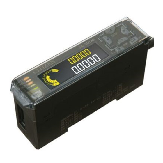
2. Product Overview 2-1 Outline When connected to a detector, the SA-SD controller can be used to measure size and perform pass/fail judgments. Controller ■ Pass/ Model Characteristics Power supply Input/output fail output SA-SD1AP Master/high performance Power cable SA-SD1AP-P Master/high performance... - Page 12 Composition ■ The SA Series consists of a controller, detector connection cables, and detectors. As the controller, two types of master controller and five types of slave controller are available, and up to 15 slave units can be connected to one master unit. Four types of sensor heads are available.
-
Page 13: Connection And Installation
3. Connection and Installation 3-1 Installation of Controller Installation on the 35-mm wide DIN Attach ■ rail Fit the hook on the spring side into the DIN rail, and while pushing it forward, fit the hook on the fixing side into the DIN rail. Remove To remove, lift and disengage the hook on the fixing side whilst pushing in the (fixing side) hook... -
Page 14: Connecting To Detector
3-2 Connecting to Detector Caution ■ Keep the power OFF during wiring work. Be sure to keep the power OFF when inserting a cable into or removing it from a detector. Performing these operations with the power ON may result in electric shock or failure. -
Page 15: Changing The Length Of The Detector Cable
3-3 Changing the Length of the Detector Cable Move the protecting cover in the direction of the arrow. Protecting cover With a flat-blade screwdriver (tip width of 2 mm or less), push in the control lever (white) located at the wire insertion port, and remove the wire. - Page 16 Insert the wire into the wire insertion port as far as it will go. As in the figure below, check that the sheathed section of the wire reaches inside the wire insertion port, and that the tip of the core wires passes through the connection section.
-
Page 17: Wiring Of Power Supply
3-4 Wiring of Power Supply Warning ■ Use a power supply that falls within the specified ratings. Use a power supply of 24 VDC. Using any other power voltage may cause fire or electric shock. ■ Keep the power OFF during wiring work. Be sure to keep the power OFF during wiring work. -
Page 19: Part Names And Functions
4. Part Names and Functions 4-1 Display and Control Keys 1 2 3 Description Output 1 indicator lamp (orange) Lights when Output 1 is ON. Output 2 indicator lamp (orange) Lights when Output 2 is ON. Output 3 indicator lamp (orange) Lights when Output 3 is ON. -
Page 20: Main Body
4-2 Main Body (4) (Slave only) Note 1 Name Description Connects to a slave unit. Remove the connector cover Female connector before connecting to a slave unit. Sensor head cable connector Connects to a sensor head cable (sold separately). Digital display/control section For details, refer to next page. -
Page 21: Modes Of Use
5. Modes of Use 5-1 Overall Flow Chart Basic screen The basic screen appears when the power is turned on. On this screen, key operations can be used to switch to various modes and execute various functions. Long press for 2 s SUB display switching mode Switches the display on digital display SUB (green). -
Page 22: Sub Display Switching Mode
5-2 SUB Display Switching Mode Basic screen Long press for 2 s SUB display switching Changes alphanumeric characters Moves cursor Displays a normal measurement value. The displayed value indicates the preset, Normal measurement direction, lever ratio, or calibration function. measurement •... -
Page 23: Teaching Mode
5-3 Teaching Mode Basic screen Long press for 2 s Teaching One-point teaching Two-point teaching Three-point teaching Measurement of HIGH Master work measurement First work measurement defective work Press key. Press key. Press key. Measurement of satisfactory work Second work measurement Press key. - Page 24 Teaching method Setting This sets the HIGH and LOW setting values automatically +Tolerance = −Tolerance using one reference work. One-point teaching HIGH setting value This is used to judge work with +Tolerance a ±tolerance. Setting value [Initial status] −Tolerance LOW setting value This sets the HIGH and LOW setting values automatically using two reference works.
-
Page 25: Fine Tuning Of Low Setting Values
5-4 Fine Tuning of LOW Setting Values Basic screen Short press Fine tuning of LOW setting values [For reference] If no keys are pressed for five seconds, the display returns automatically to the basic screen, and the settings are established. Pressing the LEFT/RIGHT key moves the cursor between digits and pressing the UP/DOWN key increases/decreases the value. -
Page 26: Bank Mode
5-6 Bank Mode In this mode, HIGH and LOW setting values can be written into designated banks (1 to 3) and read out from those banks. By using the bank function, settings for items to be measured can be stored in the bank in advance, and these settings can then be read out easily when required. - Page 27 Basic screen Long press for 2 s Bank mode Select SAVE (write) or LOAD (read out). After selecting, press the DOWN key. Select the bank to be written into or read from. After selecting, press the ENTER key. Select YES (execute). After selecting, press the ENTER key.
-
Page 28: Preset
5-7 Preset Preset is a function that determines a reference for measurement values using a master work, etc. When the preset operation is performed, the current value becomes the preset value. If 0 is set as the preset value, the current value becomes 0. Press the Preset key while a master work is being measured. -
Page 29: Key Lock
5-8 Key Lock Hold down the ENTER and EXIT keys simultaneously for three seconds. The display will show LOCK ON, and display will then return automatically to the basic screen. For reference ■ LOCK ACT will be displayed when any key is pressed. The external input function will still be in effect. -
Page 31: Parameter Settings
6. Parameter Settings 6-1 Setting the SET No. Parameters Parameter name Setting values Remarks Basic settings (BASIC) Sets a HIGH setting value for pass/fail judgment. HIGH setting value (HI.SET) −199.9999 to 199.9999 (mm) [Default: 5.0000] Sets a LOW setting value for pass/fail judgment. LOW setting value (LO.SET) −199.9999 to 199.9999 (mm) [Default: 1.0000]... - Page 32 Detailed settings (ADVANC) HOLD settings (HOLD) Selects a hold mode. S-H (Sample hold) / P-H (Peak hold) / B-H (Bottom hold) / P-P (Peak-to-peak hold) / Measurement mode (MEAS) P-P/2 (Peak-to-peak hold/2) / NG-H (NG hold) / SLF.S-H (Self sample hold) / SLF.P-H (Self peak hold) / SLF.B-H (Self bottom hold) [Default: S-H]...
- Page 33 Detailed settings (continued from the preceding page) Alarm settings (ALARM) Sets the delay time (changeable in 1 ms increments) from the time the sensor head comes into upthrust position to the Alarm delay time (DELAY) time the alarm activates. 1 to 1,000 [Default: 1,000] Upthrust check Sets the upthrust check ON/OFF.
- Page 34 Calibration settings (CALIB) When a sensor head is replaced, carrying out zero and span adjustment reduces the errors existing at installation Calibration select time. (CAL.SEL) DEFAUL (Default) / USER (Set by user) [Default: DEFAUL] ∗ When calibration select is set to USER (setting by user) The controller moves the spindle to the zero point (which Captured measurement value constitutes the calibration reference), and captures the...
-
Page 35: Basic Settings (Basic)
6-1 Basic Settings (BASIC) 6-1-1 HIGH Setting Value (HI.SET) Parameter name Setting value Remarks Sets a HIGH setting value for pass/fail judgment. HIGH setting value (HI.SET) −199.9999 to 199.9999 (mm) [Default: 5.0000] : Included : Not included HIGH HIGH setting value LOW setting value Operation procedure ■... -
Page 36: Low Setting Value (Lo.set)
6-1-2 LOW Setting Value (LO.SET) Parameter name Setting value Remarks Sets a LOW setting value for pass/fail judgment. LOW setting value (LO.SET) −199.9999 to 199.9999 (mm) [Default: 1.0000] : Included : Not included HIGH HIGH setting value LOW setting value Operation procedure ■... -
Page 37: Hysteresis (Hyster)
6-1-3 Hysteresis (HYSTER) Parameter name Setting value Remarks Judgment may be unstable due to measurements fluctuating around the HIGH or LOW setting value. A large hysteresis value Hysteresis (HYSTER) can prevent this chattering effect. 0.0000 to 199.9999 (mm) [Default: 0.0030] With HYSTER set to 0: With HYSTER set to non 0: Chattering makes judgment output unstable. -
Page 38: Teaching (Teach)
6-1-4 Teaching (TEACH) Parameter name Setting value Remarks Sets the method for automatic teaching of tolerance. Teaching mode (TEACH) TCH.1 (One-point) / TCH.2 (Two-point) / TCH.3 (Three-point) [Default: TCH.1] Teaching method Setting This sets the HIGH and LOW setting values automatically +Tolerance = −Tolerance using one reference work. -
Page 39: Tolerance <±> (Tol <±>)
6-1-5 Tolerance <±> (TOL <±>) Parameter name Setting value Remarks When executing the one-point teaching, this parameter is set in order to provide a tolerance from which the HIGH and LOW setting values are derived, with the master work measurement Tolerance <±>... -
Page 40: Preset (Pr.val)
6-1-6 Preset (PR.VAL) Parameter name Setting value Remarks Sets the reference value when the preset function is turned ON. Preset value (PR.VAL) −199.9999 to 199.9999 (mm) [Default: 0.0000] Preset is a function that adds the set value to a measured value. If a preset value is set, the current value becomes the preset value when the controller executes the preset. -
Page 41: Select Preset Data (Pr.obj)
6-1-7 Select Preset Data (PR.OBJ) Parameter name Setting value Remarks When the preset function is turned ON, this parameter selects the type of current value (NORM.V or JUDGE.V) to which the Select preset data (PR.OBJ) offset value is applied. NORM.V (normal measurement value) / JUDGE.V (judgment value) [Default: NORM.V] Operation procedure... -
Page 42: Preset Save (Pr.save)
6-1-8 Preset Save (PR.SAVE) Parameter name Setting value Remarks If Preset save is set to ON, the preset and offset values are written to an EEPROM so that they are retained after the power is Preset save (PR.SAVE) turned OFF. ON / OFF [Default: OFF] Operation procedure... -
Page 43: Measurement Direction (Direct)
6-1-9 Measurement Direction (DIRECT) Parameter name Setting value Remarks Selects between normal and reversed display of the measurement value when the spindle of the sensor head is Measurement direction (DIRECT) pushed in during measurement. NORMAL (Normal) / REVERS (Reverse) [Default: NORMAL] Operation procedure ■... -
Page 44: Lever Ratio (Lever)
6-1-10 Lever Ratio (LEVER) Parameter name Setting value Remarks If a measurement point is on a lever, the measurement value can be displayed as detected value × lever ratio. Lever ratio (LEVER) 0.1 to 100.0 [Default: 1.0] The figure below shows a lever ratio of 2:1. When the lever ratio is set to "2,"... -
Page 45: Response Time (Speed)
6-1-11 Response Time (SPEED) Parameter name Setting value Remarks Sets the period between the time the sensor head starts measurement and that at which the measurement value is determined. Response time (SPEED) This parameter is effective for stabilizing measurement values. 3 / 5 / 10 / 100 / 500 / 1,000 (ms) [Default: 100] Internal value update... -
Page 46: Output Behavior (Output)
6-1-12 Output Behavior (OUTPUT) Parameter name Setting value Remarks Selects behavior of judgment output. Output behavior (OUTPUT) N.O. (Normally open) / N.C. (Normally closed) [Default: N.O.] HIGH setting value HIGH設定値 LOW setting value LOW設定値 N.O. N.O.の場合 N.C. N.C.の場合 Operation procedure ■... -
Page 47: Detailed Settings (Advanc)
6-2 Detailed Settings (ADVANC) 6-2-1 Hold Settings Measurement mode Function Refer to (MEAS) Sample hold When (and only when) the external input is ON, the 6-2-1-1 controller holds and outputs the judgment value (S-H) Sample Hold Settings (JUDGE.V). When the external input is OFF, the judgment value (JUDGE.V) is updated and output (real-time output). - Page 48 6-2-1-1 Sample Hold Settings Parameter name Setting value Remarks Selects a hold mode. S-H (Sample hold) Measurement mode (MEAS) P-H / B-H / P-P / P-P/2 NG-H SLF.S-H / SLF.P-H / SLF.B-H [Default: S-H] Selects the external trigger input behavior. Trigger mode (TRG) HOLD (Hold) / 1SHOT(One shot) [Default: HOLD]...
- Page 49 Sample hold (Trigger mode: One shot) ■ The held data is updated when the external trigger input is turned ON (at a rising edge). HIGH setting value LOW setting value TRIG TRIG display TRIG TRIG TRIG (Light OFF) (消灯) HOLD display HOLD (消灯)...
- Page 50 6-2-1-2 Peak Hold Settings Parameter name Setting value Remarks Selects a hold mode. P-H (Peak hold) B-H (Bottom hold) Measurement mode (MEAS) P-P (Peak-to-peak hold) P-P/2 (Peak-to-peak hold/2) NG-H (NG hold) SLF.S-H / SLF.P-H / SLF.B-H [Default: S-H] Selects the external trigger input behavior. Trigger mode (TRG) HOLD (Hold) / 1SHOT (One shot) [Default: HOLD]...
- Page 51 Peak hold (Trigger mode: One shot) ■ While the external trigger input is OFF, the peak value is constantly updated, but this is an internal process and it does not appear on the display or as the judgment output. When the external trigger input is turned ON (at a rising edge), the internally updated peak value becomes the new hold value.
- Page 52 6-2-1-3 NG Hold Settings Parameter name Setting value Remarks Selects a hold mode. S-H (Sample hold) Measurement mode (MEAS) P-H / B-H / P-P / P-P/2 NG-H (NG hold) SLF.S-H / SLF.P-H / SLF.B-H [Default: S-H] NG hold ■ The judgment output is held when the judgment value becomes HIGH or LOW whilst the external trigger input is OFF.
- Page 53 Operation procedure ■ Long press 2秒長押し for 2 s BASIC CALC COPY BANK CALIB RESET MAINTE ALL.IN EXT.IN EXT.OUT DIGIT ANALOG ANA.HI ANA.LO ALARM Cancel Select 選択 キャンセル P-P/2 SLF.S-H SLF.P-H SLF.B-H Commit 確定 6- 23...
- Page 54 6-2-1-4 Self Sample Hold (Static Width) Parameter name Setting value Remarks Selects a hold mode. S-H (Sample hold) P-H / B-H / P-P / P-P/2 Measurement mode (MEAS) NG-H (NG hold) SLF.S-H (Self sample hold) SLF.P-H (Self peak hold) SLF.B-H (Self bottom hold) [Default: S-H] Sets the reference level for the hold function using the self Self trigger level...
- Page 55 Note ■ An indefinite state is held on occurrence of any of the following: The power is turned ON The reset input is ON A sensor head disconnection error or upthrust error (alarm) is canceled If the input value falls below the self trigger level before settling within the static width, the controller enters an alarm state.
- Page 56 6-2-1-5 Self Sample Hold (Delay Timer) Parameter name Setting value Remarks Selects a hold mode. S-H (Sample hold) P-H / B-H / P-P / P-P/2 Measurement mode (MEAS) NG-H (NG hold) SLF.S-H (Self sample hold) SLF.P-H (Self peak hold) SLF.B-H (Self bottom hold) [Default: S-H] Sets the reference level for the hold function using the self Self trigger level...
- Page 57 Note that, with this type of self sample hold, the judgment output is not the same as the judgment value. After the input value exceeds the specified self trigger level (in the case of the self trigger edge direction being UP), the judgment output is all OFF during the time set by the delay timer. When self sample hold is selected, external trigger input has no effect.
- Page 58 6-2-1-6 Self Peak Hold/Self Bottom Hold Parameter name Setting value Remarks Selects a hold mode. S-H (Sample hold) P-H / B-H / P-P / P-P/2 Measurement mode (MEAS) NG-H (NG hold) SLF.S-H (Self sample hold) SLF.P-H (Self peak hold) SLF.B-H (Self bottom hold) [Default: S-H] Selects the external trigger input behavior.
- Page 59 Self peak hold (Trigger mode: One shot) ■ After the input value exceeds or falls below the specified self trigger level (depending on the specified self trigger edge direction), constant updating of the peak value is performed automatically. However, this is an internal process, and does not appear on the display or as the judgment output.
- Page 60 Operation procedure ■ Long press for 2 s Select Cancel Select Cancel Select Cancel Shift between Change numerical digits values Select Cancel Commit 6- 30...
-
Page 61: All Input
6-2-2 All Input Parameter name Setting value Remarks When a trigger is input to a master unit, the signal can be input to all connected slave units simultaneously. All input (ALL IN) ONE (Single) / ALL (All) [Default: ONE] When the trigger or preset inputs into all of the master and slave units which are connected together share the same timing, the trigger/preset inputs into the master unit can be set to be input into all of the slave units. -
Page 62: External Input
6-2-3 External Input Parameter name Setting value Remarks For input 1/input 2/input 3 of external inputs, selects one of four input signal types. P/R/T (Preset/Reset/Trigger) External input (EXT.IN) BANK/P (Bank A/B/Preset) BANK/R (Bank A/B/Reset) BANK/T (Bank A/B/Trigger) [Default: P/R/T] External input Input 1 Input 2 Input 3... -
Page 63: External Output
6-2-4 External Output Parameter name Setting value Remarks For output 1/output 2/output 3 of external outputs, selects one of four output signal types. 3VAL (HI, GO, LO) External output (EXT.OUT) 2VAL (HIorLO, INRANGE, ALARM) LOGIC (LOGIC, ALARM) LOGIC2 (ALLGO, GO, ALARM) [Default: 3VAL] Details of outputs are as follows: HIGH... - Page 64 Related information ■ For details of the input/output circuit, refer to "7-1-1 Input/Output Circuit." For details of setting output behavior, refer to "6-1-12 Output Behavior (OUTPUT)." 6- 34...
-
Page 65: Display Digits
6-2-5 Display Digits Parameter name Setting value Remarks Changes the number of digits shown after the decimal point on the digital display. Display digits (DIGIT) 0.1 / 0.01 / 0.001 / 0.0001 [Default: 0.0001] Operation procedure ■ Long press for 2 s Select Cancel Select... -
Page 66: Analog Output Settings
6-2-6 Analog Output Settings 6-2-6-1 Analog Scaling Parameter name Setting value Remarks For analog output, sets the upper and lower limits corresponding to judgment value (JUDGE.V) converted to current (4 to 20 mA). Analog scaling (ANALOG) DEFALT (Default) / FREE (Free) [Default: DEFALT] If set to DEFALT, the lower limit is fixed at 0.0000, and the output is 4 mA. - Page 67 6-2-6-2 Scaling Upper Limit/Scaling Lower Limit Parameter name Setting value Remarks This can be set only when analog scaling is set to FREE. Scaling upper limit (ANA.HI) It sets the judgment value that outputs a current of 20 mA −199.9999 to 199.9999 (mm) [Default: 10.0000] This can be set only when analog scaling is set to FREE.
-
Page 68: Eco Mode
6-2-7 Eco Mode Parameter name Setting value Remarks Saves energy by turning off the backlight of the controller display when the screen is not being used. Eco mode (ECO) ON / OFF [Default: OFF] If eco mode is set to ON, the screen backlight is turned OFF if no keys operations are performed for 30 seconds. -
Page 69: Alarm Settings
6-2-8 Alarm Settings Parameter name Setting value Remarks Sets the delay time (changeable in 1 ms increments) from the time the sensor head comes into upthrust position to the time the Alarm delay time (DELAY) alarm activates. 1 to 1,000 [Default: 1,000] Upthrust check Sets the upthrust check ON/OFF. - Page 70 6-2-8-1 Alarm Delay Time Parameter name Setting value Remarks Sets the delay time (changeable in 1 ms increments) from the time the sensor head comes into upthrust position to the time the Alarm delay time (DELAY) alarm activates. 1 to 1,000 [Default: 1,000] Can be set such that a momentary upthrust will not activate the alarm.
- Page 71 6-2-8-3 Upthrust Check Setting Value Parameter name Setting value Remarks Upthrust check setting value Sets the threshold level of the upthrust check. (PRS.SET) −199.9999 to 199.9999 (mm) [Default: 10.0000] Operation procedure ■ Long press for 2 s Select Cancel Shift between Change numerical digits values...
- Page 72 6-2-8-4 Catching Check Parameter name Setting value Remarks Catching check Sets the catching check ON/OFF. (CAT.CHK) ON / OFF [Default: OFF] If, due to aging, spindle movement becomes poor and the spindle does not return to the correct position, then accurate measurement cannot be performed.
- Page 73 6-2-8-5 Number of Connected Units Check (Master Unit Only) Parameter name Setting value Remarks If controllers are connected, this performs a check when the power is turned ON confirming that the number of connected units Number of connected units check has not changed.
-
Page 74: Calculation Settings (Master Unit Only)
6-3 Calculation Settings (Master Unit Only) 6-3-1 Calculation Mode Parameter name Setting value Remarks This mode carries out calculations using measurements from each connected controller, and outputs the judgment results on the master unit display and from the master unit. Calculation mode (MODE) CALC (Calculates) / NOCALC (Does not calculate) [Default: NOCALC]... - Page 75 Calculation app ■ Application Function Remarks The calculation value is the maximum value Maximum of the measurements from all the connected value Maximum controllers. One or value more units (MAX) [Calculation value] = [Maximum value] The calculation value is the minimum value of the measurements from all the connected Minimum Minimum...
-
Page 76: Copy Settings
6-4 Copy Settings 6-4-1 Select Individual Items to Be Copied (Master Unit Only) Parameter name Setting value Remarks Items to be copied are selected individually. Copy select (CPY.SEL) YES / NO [Default: YES] The settings on the master unit can be copied to the slave units that are connected to it. Each item to be copied can be selected individually, or all settings can be selected together. -
Page 77: Select All Items To Be Copied (Master Unit Only)
Note ■ The other items are set to YES/NO using the same kind of operation procedure as that for HI.SET. Only the current settings are copied. The settings stored in banks cannot be copied. When setting the basic settings (BASIC) and detailed settings (ADVANC) items, the preset key can be used to select or deselect individual items for copying. -
Page 78: Execute Copy (Master Unit Only)
6-4-2 Execute Copy (Master Unit Only) Parameter name Setting value Remarks The master unit copies the items selected for copying (individually selected or all items) to the slave units. Execute copy (CPY.EXE) YES / NO [Default: YES] When copy is executed, the master and slave units show NOW on digital display SUB (green), and COPY on digital display MAIN (white). -
Page 79: Bank Settings
6-5 Bank Settings Parameter name Setting value Remarks Selects the settings to be read out from those stored in a bank. ALL (All) Select bank storage (BNK.DAT) THRS (HIGH setting value, LOW setting value) THRS.PR (HIGH setting value, LOW setting value, Preset value) [Default: ALL] Banks are storage areas. -
Page 80: Calibration Settings
6-6 Calibration Settings Parameter name Setting value Remarks When a sensor head is replaced, carrying out zero and span adjustment reduces the errors existing at installation time. Calibration select (CAL.SEL) DEFAUL (Default) / USER (Set by user) [Default: DEFAUL] (1) Measure zero (2) Measure target (3) Enter theoretical value of span point. -
Page 81: Resetting
6-7 Resetting Parameter name Setting value Remarks This resets all controller settings to the factory defaults. Reset (RESET) YES / NO Operation procedure ■ Long press for 2 s Select Commit Automatic Automatic Note ■ Resetting does not alter the settings stored in banks. Calibration settings are not reset. -
Page 82: Maintenance
6-8 Maintenance Parameter name Setting value Remarks Displays in meters the accumulated distance that the spindle has Total stroke work history (SUM .REC) moved. Maximum peak value (MAX. VAL) Displays the maximum peak value reached during operation. Maximum peak value history Displays in meters the accumulated distance that the spindle had moved when the maximum peak value was reached. -
Page 83: External Input/Output
7. External Input/Output 7-1 Interface 7-1-1 Input/Output Circuit SA-SD1AP, SA-SD1AP-P ■ Color Signal Remarks Brown − 24 VDC Black Output 1 White Output 2 Refer to "6-2-4 External Output." Black/gray Output 3 Pink External input 1 Violet External input 2 Refer to "6-2-3 External Input."... - Page 84 NPN output type ■ (Brown) +V (Note 1) (Black) Output 1 Load Load (White) Output 2 Load (Black/gray) Output 3 24 VDC ±10% (Pink) External input 1 − (Violet) External input 2 ∗S1 (Pink/violet) External input 3 ∗S1 ∗S1 (Blue) 0 V (Note 1) (Gray) Analog current output (4 to 20 mA) (Note 2) (Shield) Analog ground (Note 2) (Note 3) Load...
- Page 85 Note 1: Only master units are equipped with +V and 0 V. Power is supplied to slave units through connectors. Note 2: Only SA-SD1A model is equipped with an analog current output terminal and a grounding terminal for analog signals. Note 3: Use shielded wires for analog outputs.
-
Page 86: Minimum Input Time
7-2-3 Minimum Input Time The minimum input time depends on input signal type. Preset input ■ Preset Release preset Min 20 ms Min 1.5 s Min 20 ms Reset input ■ Min 20 ms Min 20 ms Trigger input ■ Min 2 ms Min 2 ms Bank A/B input... -
Page 87: Troubleshooting
8. Troubleshooting 8-1 Errors If an error occurs during operation, an error No. is displayed, as shown in the table below. Cause Solution E100 Both NPN and PNP output types are Connect only the same output type. connected. E110 Up to 15 slave units can be connected to one master Too many units are connected. -
Page 88: What To Do If A Problem Occurs
8-2 What to Do If a Problem Occurs Problem Please perform these checks Power does not turn ON. Is the power supply connected correctly? Is power being supplied correctly? Has the power been connected with the polarity (+/−) reversed? Is the power voltage correct? Is the current capacity sufficient? The measurement remains Is a hold signal being input? -
Page 89: Specifications
9. Specifications 9-1 Specifications Master unit Slave unit Type High performance type Standard type Wire saving type SA-SD1AP SA-SD1AC SA-SD1C Model SA-SDNC SA-SD1AP-P SA-SD1AC-P SA-SD1C-P Number of connectable Up to 15 slave units to one master unit units Power voltage 24 VDC ±10% Including ripple of 0.5 V (P-P) Current consumption 70 mA or less (when connected to sensor heads) - Page 90 Master unit Slave unit Type High performance type Standard type Wire saving type SA-SD1AP SA-SD1AC SA-SD1C Model SA-SDNC SA-SD1AP-P SA-SD1AC-P SA-SD1C-P Response time Switchable between 3 ms, 5 ms, 10 ms, 100 ms, 500 ms, and 1,000 ms Output 1 indicator lamp Orange LED (Lit when Output 1 is ON) Output 2 indicator lamp Orange LED (Lit when Output 2 is ON)
-
Page 91: Outline Dimensional Drawings
9-2 Outline Dimensional Drawings SA-SD1AP and SA-SD1AP-P 15 mm or more 20 mm or more Compliant with 35- mm width DIN rail R 30 mm or R 30 mm or more more SA-SD1AC, SA-SD1AC-P, SA-SD1C, and SA-SD1C-P 20 mm or more 15 mm or more Compliant with 35- mm width DIN rail... - Page 92 Certificate of Quality Approval This product is certified to be in compliance with the company standards of Citizen Finedevice. CITIZEN FINEDEVICE CO., LTD. 6663-2, Funatsu, Fujikawaguchiko-machi, Minamitsuru-gun, Yamanashi 401-0395 TEL: 0555-22-1141 FAX: 0555-23-2106 URL: http://cfd.citizen.co.jp 9- 4...
- Page 94 CITIZEN FINEDEVICE CO., LTD. 6663-2, Funatsu, Fujikawaguchiko-machi, Minamitsuru-gun, Yamanashi 401-0395 TEL: 0555-22-1141 FAX: 0555-23-2106 U4M0060(2)
Need help?
Do you have a question about the SA-SD and is the answer not in the manual?
Questions and answers