
Related Manuals for Extron electronics DTP2 T 212


Summary of Contents for Extron electronics DTP2 T 212
- Page 1 User Guide DTP Systems DTP2 T 212 HDMI Switcher with Integrated DTP Transmitter 68-2915-01 Rev. A 12 19...
- Page 2 Safety Instructions Safety Instructions • English Istruzioni di sicurezza • Italiano AVVERTENZA: Il simbolo, , se usato sul prodotto, serve ad WARNING: This symbol, ,when used on the product, is avvertire l’utente della presenza di tensione non isolata pericolosa intended to alert the user of the presence of uninsulated dangerous all’interno del contenitore del prodotto che può...
- Page 3 ついては、 エクス トロンのウェブサイ ト より 『Extron Safety www.extron.com and Regulatory Compliance Guide』 (P/N 68-290-01) をご覧ください。 Copyright © 2019 Extron Electronics. All rights reserved. Trademarks All trademarks mentioned in this guide are the properties of their respective owners. The following registered trademarks( ®...
- Page 4 FCC Class A Notice This equipment has been tested and found to comply with the limits for a Class A digital device, pursuant to part 15 of the FCC rules. The Class A limits provide reasonable protection against harmful interference when the equipment is operated in a commercial environment. This equipment generates, uses, and can radiate radio frequency energy and, if not installed and used in accordance with the instruction manual, may cause harmful interference to radio communications.
- Page 5 Conventions Used in this Guide Notifications The following notifications are used in this guide: CAUTION: Risk of minor personal injury. ATTENTION : Risque de blessure mineure. ATTENTION: • Risk of property damage. • Risque de dommages matériels. NOTE: A note draws attention to important information. TIP: A tip provides a suggestion to make working with the application easier.
-
Page 7: Table Of Contents
HDCP ............20 Rack Mounting ..........49 TMDS Output Format ........20 Furniture Mounting......... 49 Color Bit Depth and Deep Color Support ..20 Tie to Output A (HDMI Output) ....... 21 Audio Configuration ........21 DTP2 T 212 • Contents... - Page 8 DTP2 T 212 • Contents viii...
-
Page 9: Introduction
Transmits HDMI plus control and analog audio up to 330 feet (100 meters) or 230 feet (70 meters) over a shielded CATx cable — The DTP2 T 212 provides high reliability and maximum performance on an economical and easily installed cable infrastructure. - Page 10 Analog stereo audio embedding — Analog stereo audio signals can be selectively • embedded onto the digital video output signal. The DTP2 T 212 can be set to pass the embedded digital audio, embed the analog audio, or to automatically embed the analog audio when no digital audio is detected.
- Page 11 External Extron Everlast power supply included — Provides worldwide power • compatibility with high-demonstrated reliability and low power consumption. • Extron Everlast Power Supply is covered by a 7‑year parts and labor warranty. DTP2 T 212 • Introduction...
-
Page 12: Application Diagram
Control Control HDMI HDMI HDBT Projector LINK OUTPUTS POWER OVER DTP2 AUDIO 0.8A MAX RS-232 Local Monitor Tx Rx Tx Rx DTP2 IN DTP2 R 212 DTP Receiver Figure 1. Application Diagram of the DTP2 T 212 DTP2 T 212 • Introduction... -
Page 13: Installation
Connect Over DTP RS‑232 and IR control. Connect a serial RS-232 signal, a modulated IR signal, or both into this 3.5 mm, 5-pole captive screw port ( ) for bidirectional RS-232 and IR communication. DTP2 T 212 • Installation... -
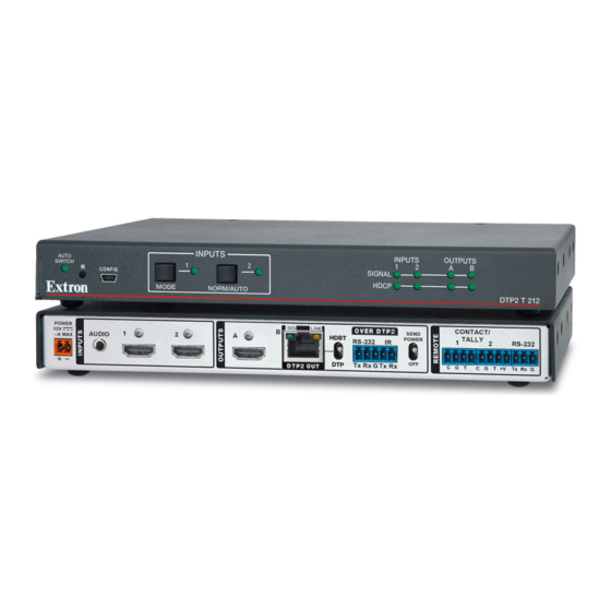
Page 14: Rear Panel Features
• A mono audio connector consists of the tip and sleeve. Sleeve ( ) 3.5 mm Stereo Plug Connector • A stereo audio connector consists of the tip, ring, (balanced) and sleeve. DTP2 T 212 • Installation... - Page 15 Over TP RS‑232 and IR port — Connect a serial RS-232 signal, a modulated IR signal, or both into this 3.5 mm, 5-pole captive screw port for bidirectional RS-232 and IR communication (see Over TP RS‑232 and IR Control on page 12 to wire the connector). DTP2 T 212 • Installation...
- Page 16 RS-232 2.0A MAX RS-232 LINK CONFIG OUTPUT Local DTP2 R 211 Rx G C G T CATx Cable Power Supply up to 330' (100 m) Figure 3. Send Power Toggle Switch Configuration Local Power Supply DTP2 T 212 • Installation...
-
Page 17: Wiring Connections
Coupez l’alimentation avant d’effectuer tout raccordement. ATTENTION: • Do not connect power to the DTP2 T 212 until you have read the ATTENTION notifications below. • Ne branchez pas l’alimentation au DTP2 T 212 avant d’avoir lu les mises en garde «... - Page 18 The power supply shall not be permanently fixed to building structure or similar structure. • La source d’alimentation ne devra pas être fixée de façon permanente à la structure de bâtiment ou à d’autres structures similaires. DTP2 T 212 • Installation...
-
Page 19: Tp Connector And Cable Recommendations
Do not comb the cable for the first 20 meters, where cables are straightened, aligned, and secured in tight bundles. • Loosely place cables and limit the use of tie wraps or hook-and-loop fasteners. • Separate twisted pair cables from AC power cables. DTP2 T 212 • Installation... -
Page 20: Remote Rs-232 Control
The IR Tx and Rx line pairs and the RS-232 Tx and Rx line pairs must each cross once between their connectors and the source or destination. • The length and preparation of exposed wires is important (see the wiring ATTENTION: on page 9 for details). DTP2 T 212 • Installation... -
Page 21: Contact Port
Loosely place the included tie wrap around the HDMI connector and the LockIt lacing bracket as shown. While holding the connector securely against the lacing bracket, use pliers or similar tools to tighten the tie wrap, then remove any excess length. DTP2 T 212 • Installation... -
Page 22: Operation
If auto-input switching is in effect, these buttons are disabled, but the LEDs continue to light to indicate the selected input (see Enabling Auto‑Input Switching on page 19 for the procedure to set up automatic input selection or the SIS command Auto Switch Mode (unsolicited) on page 42. DTP2 T 212 • Operation... -
Page 23: Operations
• The transmitter reads the available EDID information from the connected output device and writes it to memory on each input. Power on the input devices. DTP2 T 212 • Operation... -
Page 24: Selecting An Input
LEDs blink once. NOTE: Front panel lockout can only be enabled or disabled via SIS commands (see Front Panel Lockout (unsolicited) on page 42) or PCS (see Front Panel Lockout (Exec Mode) on page 30). DTP2 T 212 • Operation... -
Page 25: Connecting To The Usb Port
CONFIG HDCP MODE NORM/AUTO DTP2 T 212 DTP2 T 212 Front Panel Figure 8. USB Port Connection If this is the first time connecting a DTP2 T 212 to this USB port on your computer, the Found New Hardware Wizard opens. On the first screen, indicate if it is necessary to connect to Windows Update to search the web for the driver needed to communicate with the transmitter via the USB port. - Page 26 USB port. You do not see the wizard again unless you connect the transmitter to a different USB port on your computer. Configure the transmitter as desired using SIS commands (see SIS Commands starting on page 37) or Product Configuration Software (see Configuration Software starting on page 22). DTP2 T 212 • Operation...
-
Page 27: Configuration
The assigned EDID is stored to an EEPROM, which is located at the HDMI input. The stored EDID is retained until a reset is initiated. Hot Plug Detect (HPD) HPD remains high on all inputs while the unit is powered on. The HPD drops low only while EDID is updated. DTP2 T 212 • Operation... -
Page 28: Hdcp
• Force 8‑bit Video Output Color Bit This can be disabled or changed using SIS commands (see Depth on page 42) or PCS (see Output Configuration). DTP2 T 212 • Operation... -
Page 29: Tie To Output A (Hdmi Output)
PCS (see Output Configuration page 25). Output Audio Configuration Embedded audio can be enabled or disabled on each output individually or globally via Output Audio Configuration Output SIS commands (see on page 46) or PCS (see Configuration). DTP2 T 212 • Operation... -
Page 30: Configuration Software
If there is no direct link to your software, click the Software link ( ) and scroll down to the alphabetic navigation bar (see figure 12). Figure 12. Alphabetic Navigation Bar Click the appropriate letter to locate the software. Click Download and follow the on-screen instructions. DTP2 T 212 • Configuration Software... -
Page 31: Using Pcs Software
The Product Configuration Software opens to the Device Discovery screen (see figure 13). Figure 13. PCS Device Discovery Screen Select the DTP2 T 212 device by clicking on it to highlight it in the list (see figure 13, Click Connect ( DTP2 T 212 • Configuration Software... -
Page 32: Input/Output Configuration
The Input Configuration panel (see figure 15) allows the user to view the input status, and configure HDCP Authorized and Audio Format. Figure 15. Input Configuration Panel Signal Type — Connection status shows HDMI when an active HDMI signal is present. DTP2 T 212 • Configuration Software... - Page 33 • Follow Input — Encrypts the output only when required by the selected input source (default). • Always Encrypt Output — Always encrypts the output, regardless of the HDCP status of the input source. DTP2 T 212 • Configuration Software...
-
Page 34: Edid Minder
) on the global navigation bar to open the EDID Minder Minder icon (see figure 17, page. EDID can be set to match output rate, a custom user-defined EDID, or a factory setting. Figure 17. EDID Minder Page DTP2 T 212 • Configuration Software... - Page 35 Navigate to the desired EDID file location and select it ( NOTE: Valid EDID files have a .bin file extension. ). The EDID is added to the Available EDID panel. Click the Open button ( DTP2 T 212 • Configuration Software...
-
Page 36: General Settings
Serial Host Control Port Mode, CEC Communications, and Unit Information. Click the General Settings icon (see figure 20, ) on the global navigation bar to open the General Settings page. Figure 20. General Settings Page DTP2 T 212 • Configuration Software... - Page 37 Firmware Version • Device Name Figure 22. Device Name Window Click the Hardware Settings button (see figure 20, ), and then click the Device Name tab to view or change the Device Name (see figure 22). DTP2 T 212 • Configuration Software...
- Page 38 Over TP Serial Device Control — The receiver controls the transmitter via the • Over TP RS-232 port on the receiver, through the RS-232 port on the transmitter. The Over TP RS-232/IR port on the transmitter is disabled. DTP2 T 212 • Configuration Software...
- Page 39 Select a radio button (see figure 28) to pass the original embedded digital audio (Follow Input) or replace it with analog audio by selecting which input to replace the audio with the analog audio (Input 1 or Input 2). DTP2 T 212 • Configuration Software...
-
Page 40: Av Controls Panel
Disconnect the device from PCS View the hardware Settings Reset Device to factory default Update Firmware Access the DTP2 T 212 Help file View information About This Module Extron PCS Help File For assistance, Extron PCS Help contains complete information about using the PCS program to configure the DTP2 T 212. -
Page 41: Updating Firmware
Updating Firmware Firmware for the DTP2 T 212 can be updated using PCS. Updates to the DTP2 T 212 firmware are made available periodically via the Extron website. You can find out what version of firmware is currently loaded on your switcher by entering the SIS Q command via... -
Page 42: Uploading Firmware To The Switcher
Open PCS via the desktop Start menu, desktop icon, or toolbar icon. Unless changed in the installation of PCS, make the following selection from the Start menu: Start > All Programs > Extron Electronics > Extron Product Configuration Software > Extron Product Configuration Software The Product Configuration Software window opens to the Device Discovery screen (see figure 31). - Page 43 The Product Configuration Software opens to the device page (see figure 32). Figure 32. DTP2 T 212 PCS Device Page Click the Device Menu arrow next to the name of the device ( The Device Menu drops down. Figure 33. DTP2 T 212 Device Menu Click Update Firmware (see figure 33,...
- Page 44 Click Connect, or double click on the device. The device reconnects to the software. NOTE: The original factory-installed firmware is permanently available on the DTP2 T 212. If the attempted firmware upload fails for any reason, the switching transmitter reverts to the factory version. DTP2 T 212 • Configuration Software...
-
Page 45: Sis Commands
No response is required from the host. The switcher sends the following message when it is first powered on: (C) Copyright 2019, Extron Electronics DTP2 T 212, Vn.nn, 60-1587-52 Vn.nn is the firmware version number. •... -
Page 46: Error Responses
ASCII to Hex Conversion Table NOTE: For commands and examples of computer or device responses mentioned in this guide, the character “0” is used for the number zero and “O” is the capital letter “o.” DTP2 T 212 • SIS Commands... -
Page 47: Symbol Definitions
= DTP/HDBT switch position 0 = DTP (default) 1 = HDBT X1& = Permanent tie mode 0 = Disable 1 = Output 1 tied to input 1 2 = Output 1 tied to input 2 DTP2 T 212 • SIS Commands... - Page 48 2 = CEC mode 2 enabled but no device detected (unidirectional) 3 = CEC mode 2 enabled and device detected (unidirectional) 4 = CEC mode 4 enabled but no device detected (bidirectional) 5 = CEC mode 4 enabled and device detected (bidirectional) DTP2 T 212 • SIS Commands...
- Page 49 (Example: %2A%07%FF) X3& = CEC address byte: In the form of percentage sign followed by 2 hexadecimal digits (Example: = Extron output ( ) to TV ( NOTE: Unless otherwise indicated, commands are not case-sensitive. DTP2 T 212 • SIS Commands...
-
Page 50: Command And Response Table For Sis Commands
1 = On, enabled, or detected Front Panel Lockout (unsolicited) Enable or disable Executive mode View lockout status Verbose modes 2/3 KEY: X@ = On/Off 0 = Off, disabled, or undetected (default), 1 = On, enabled, or detected DTP2 T 212 • SIS Commands... - Page 51 HDCP Notification Disable green screen N0HDCP HdcpN0 Enable green screen N1HDCP HdcpN1 View HDCP notifications NHDCP X2^] HdcpN X2^] Verbose modes 2/3 KEY: X2^ 0 = Disabled, 1 = Enabled (default) = Green screen DTP2 T 212 • SIS Commands...
- Page 52 = Device name The name can have up to 24 alphanumeric characters including hyphens (-), with no spaces. The first character must be a letter, and the last character cannot be a hyphen. The default is DTP2-T-212. DTP2 T 212 • SIS Commands...
- Page 53 = Video outputs 1 to 2 = Video and sync mute 0 = Unmute video and sync (default), 1 = Mute video to black screen with sync on, 2 = Mute video and sync DTP2 T 212 • SIS Commands...
- Page 54 Hstm Verbose modes 2/3 X2&] KEY: X2& = On/Off 0 = Over TP pass through (default), 1 = Over TP serial device control Reset Reset Reset the switcher to its factory ZXXX default values. DTP2 T 212 • SIS Commands...
-
Page 55: Command And Response Table For
User selected elements (0 to 15) in the form of percent sign followed by 2 hex digits = CEC data (Example: %2A%07%FF) X3& In the form of percent sign followed by 2 hex digits (Example: %E0 = Extron output (14) to TV (0)) = CEC address byte DTP2 T 212 • SIS Commands... - Page 56 1 = Success (ACK) device detected, 2 = Unable to send %10%00 = CEC physical address: 4 hexadecimal digits (Example: for 1000) = CEC device presence: 0‑F = Device address, X = Missing, — = CEC port is off DTP2 T 212 • SIS Commands...
-
Page 57: Mounting
(for example, use of power strips). Furniture Mounting The DTP2 T 212 can be mounted under a desk, table, or podium using an under-desk mounting kit (see the mounting instructions provided with the kit). DTP2 T 212 • Mounting... - Page 58 Extron Electronics makes no further warranties either expressed or implied with respect to the product and its quality, performance, merchantability, or fitness for any particular use. In no event will Extron Electronics be liable for direct, indirect, or consequential damages resulting from any defect in this product even if Extron Electronics has been advised of such damage.
Need help?
Do you have a question about the DTP2 T 212 and is the answer not in the manual?
Questions and answers