Advertisement
Quick Links
Download this manual
See also:
User Manual
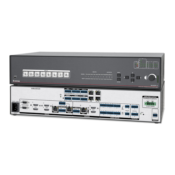
IN1608 xi Series • Setup Guide
The Extron IN1608 xi Scaling Presentation Switcher is an eight input, HDCP-compliant video scaler that accepts a wide
variety of audio and video formats and provides HDMI and DTP/HDBaseT video outputs. This guide provides instructions
for an experienced user to set up and configure IN1608 xi, IN1608 xi SA, IN1608 xi MA 70, IN1608 xi IPCP SA, and
IN1608 xi IPCP MA 70 scalers. It covers how to perform basic operations using the front panel controls and selected Simple
Instruction Set (SIS™) commands.
NOTES:
•
For full installation, configuration, menus, connector wiring, and operation details, see the IN1608 xi Series User Guide
at www.extron.com. For installation, configuration, and operation details of the IPCP Pro dual-NIC embedded control
processor, see the IPCP Pro Series User Guide.
•
The IN1608 xi Series products can also be configured via the Extron Product Configuration Software (PCS), available at
www.extron.com. For information on using PCS, see the IN1608 xi Series Help file
Installation
IN1608 xi Series Rear Panel Connectors
IN1608 xi IPCP SA
1
3
100-240V ~ 1.5 A MAX
CONFIGURABLE
2
HDMI
4
50/60 Hz
A
B
C
Figure 1.
Rear Panel Connectors, IN1608 xi IPCP SA
Power and Input Connections
AC power connector
A
Configurable analog 15-pin HD (VGA)
B
connectors (inputs 1 and 2)
HDMI inputs (inputs 3 through 6)
C
DTP inputs and corresponding RS-232/IR Over
D
DTP connectors (inputs 7 and 8)
Analog audio inputs (associated with inputs 1
E
through 6)
Mic/Line audio inputs and adjacent phantom
F
power LEDs
The IN1608 xi IPCP models feature a built-in Extron IPCP Pro dual-NIC control processor for controlling and monitoring a variety
of external devices, such as projectors and lights (see the IPCP Pro Series Setup Guide for more details).
NOTE:
The non-IPCP models have a LAN connector next to the Remote RS-232 connector (see
the illustration at right) instead of the IPCP Pro control processor.
COM 1
COM 2
COM 3
Tx Rx
G
RTS CTS
Tx Rx G
Tx Rx G
IR/SERIAL
RELAYS
1
2
1
2
C
3
R
S
G
S
G
RS-232
IR
5
7
8
Tx Rx
G
Tx Rx
SIG
LINK
SIG
LINK
OVER TP
OVER DTP
HDMI
RS-232
IR
RS-232
IR
6
DTP IN
DTP IN
Tx Rx
G
Tx Rx
Tx Rx
G
Tx Rx
INPUTS
D
Output Connections
G
H
I
J
K
M
DIGITAL I/O
AV LAN 2
AV LAN 3
1 2
3
4 G
eBUS
4
C
+V
+S
-S G
PWR OUT = 6W
AV LAN 1
LAN
L
1
R
L
3
R
L
1C
1A
SIG
LINK
1B
HDBT
HDMI
L
2
R
L
4
R
L
DTP
OUT
OUTPUTS
AUDIO INPUTS
G
H
I
E
DTP/HDBaseT output connector and
corresponding RS-232/IR Over
TP connector (output 1C)
DTP/HDBaseT mode selection switch
for twisted pair output
HDMI outputs (outputs 1A and 1B)
Analog audio outputs
Amplified audio output
(SA and MA models only)
K
AMPLIFIED OUTPUT
2x25W(8Ω)/2x50W(4Ω)
L
R
5
R
1
2
CLASS 2 WIRING
+48V
RESET
RS-232
MIC/LINE
VARIABLE
6
R
L
R
2
Tx Rx
+48V
OUTPUTS
REMOTE
F
J
L
Control Connections
Remote RS-232 port
L
IPCP Pro dual-NIC
M
embedded control
processor
(IPCP models only)
LAN connector
N
(non-IPCP models
only, see the note and
illustration below)
in
N
O
OUTPUTS
1
2
VARIABLE
L
R
G
N
AMPLIFIED OUTPUT
2x25W(8Ω)/2x50W(4Ω)
L
R
CLASS 2 WIRING
REMOTE
LAN
RESET
RS-232
Tx Rx
G
IN1608 xi SA
1
Advertisement

Subscribe to Our Youtube Channel
Related Manuals for Extron electronics IN1608 xi Series


Summary of Contents for Extron electronics IN1608 xi Series
- Page 1 IPCP Pro Series User Guide. • The IN1608 xi Series products can also be configured via the Extron Product Configuration Software (PCS), available at www.extron.com. For information on using PCS, see the IN1608 xi Series Help file...
- Page 2 RS-232 and IR Over TP Wiring on the next page). Alternatively, insert RS-232 communication to a DTP/HDBaseT endpoint via Ethernet (see the IN1608 xi Series User Guide for more information). Connect analog audio sources to the inputs via the 5-pole captive screw connectors ( ).
-
Page 3: Audio Wiring
(Tx, Rx, and G) of the 5-pole captive screw connector. To transmit and receive IR signals, connect a control device to the three rightmost poles (G, Tx, and Rx). NOTE: Alternatively, RS-232 data can be inserted via Ethernet (see the IN1608 xi Series User Guide for details). Audio Wiring Wire the audio input and output connectors as shown No Ground Here at right. -
Page 4: Front Panel Overview
IPCP Pro LED indicators — IPCP Pro models only (see the IPCP Pro Series Setup Guide for details). IN1608 xi Series Configuration To configure IN1608 xi scalers, use the front panel controls and the on-screen display (OSD) menu, the internal web pages, PCS, or SIS commands. -
Page 5: Firmware Updates
DataViewer utility or a control system to send and receive SIS commands. The table below lists a selection of SIS commands. For a full list of SIS commands and variables, see the IN1608 xi Series User Guide at www.extron.com. Command... - Page 6 Extron USA - West Extron USA - East +1.714.491.1500 +1.919.850.1000 +31.33.453.4040 +91.80.3055.3777 +1.714.491.1517 FAX +1.919.850.1001 FAX +31.33.453.4050 FAX +91.80.3055.3737 FAX © 2017 Extron Electronics All rights reserved. All trademarks mentioned are the property of their respective owners. www.extron.com 68-1916-53 Rev. A 11 17...
Need help?
Do you have a question about the IN1608 xi Series and is the answer not in the manual?
Questions and answers