SMA Sunny Island 5048 Installation Instructions Manual
Hide thumbs
Also See for Sunny Island 5048:
- Technical description manual (224 pages) ,
- Technical description (212 pages)

Related Manuals for SMA Sunny Island 5048


Summary of Contents for SMA Sunny Island 5048
- Page 1 Sunny Island 5048 Installation & Instruction Manual Technical Description Version 1.0 SI5048-11:EE4206 TBE-SI5048...
- Page 2 Home Screen #110 Inverter Meters #100 METERS #111 Inverter Device Meters #112 Inverter Total Meters #113 Inverter Slave1 Meters #114 Inverter Slave2 Meters #115 Inverter Slave3 Meters #120 Battery Meters #130 External Meters #131 External Device #132 External Total #133 External Slave1 #134 External Slave2 #135 External Slave3 #140 Generator Meters...
-
Page 3: Table Of Contents
Syntax....... . . 10 The Sunny Island 5048....11 Properties . - Page 4 Table of Contents Technologie AG Electrical Connection ..... 33 Grounding ......34 DC Connection .
- Page 5 Technologie AG Activation and Deactivation ....61 Activation / Startup ..... . . 61 Stopping .
- Page 6 14.1.9 Stopping the Sunny Island 5048 ..... .109 14.1.10 Failures ........109...
- Page 7 Conditions........110 14.2.2 Starting the Sunny Island 5048 ..... . .110 14.2.3 Stand-Alone Grid Operation .
- Page 8 Technologie AG Troubleshooting/Problem Solving ..143 19.1 Error Categories ......143 19.2 Error Confirmation .
-
Page 9: Notes On This Manual
This product may only be operated within the limits and in the intended area of application provided in this document. Do not use the Sunny Island 5048 for purposes other than those indicated in this technical description. Use of the device for other purposes can void the warranty as well as damage both the device and the system. -
Page 10: Syntax
Notes on this Manual Technologie AG 1.3 Syntax The syntax specified here for menus and parameters apply to the entire document: Menu: hash, menu number and menu name (#150 Grid Meters) Parameter: hash, menu number, dot, parameter number and parameter name (#150.01 GdRmgTm) Page 10 SI5048-11:EE4206... -
Page 11: The Sunny Island 5048
When these functions are properly used, the battery service life can be greatly extended in comparison with simpler devices. Despite the complex function of this battery inverter, the Sunny Island 5048 is easy to configure. All the settings required for operation can be quickly and easily programmed in ten steps using the "Quick Configuration Guide". - Page 12 An MMC/SD card provides uncomplicated system control, and thus makes any service work easier. The Sunny Island 5048 monitors the set voltage and frequency limits on the grid and the generator. If these limits are not within the permissible range, it disconnects the external source without interruption and goes into stand-alone grid operation.
- Page 13 Technologie AG The Sunny Island 5048 Technical Description SI5048-11:EE4206 Page 13...
- Page 14 The Sunny Island 5048 Technologie AG Master Slave Sunny Island Sunny Sunny Island Island . . . ENTE ENTE ENTE ENTE ENTE ENTE Master Slave 1 Slave 2 Sunny Sunny Sunny Island Island Island ENTE ENTE ENTE ENTE ENTE ENTE...
-
Page 15: At A Glance
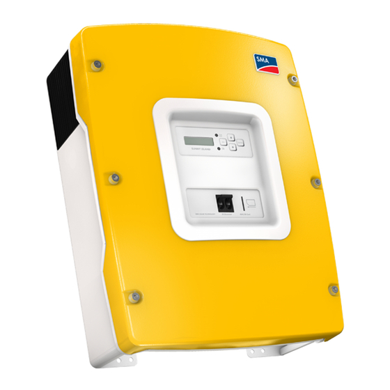
Technologie AG The Sunny Island 5048 2.2 At a Glance The following figure provides an overview of all control elements and connections of the Sunny Island 5048: Display LEDs showing device Control keys operation (green above, circuit MMC/SD breaker card... -
Page 16: Dimensions
The Sunny Island 5048 Technologie AG 2.3 Dimensions 235 mm Upper edge of the device 62 mm Upper edge wall bracket Display height 230 mm 612 mm 467 mm 235 mm 215 mm 105 mm 700 mm Page 16 SI5048-11:EE4206... -
Page 17: Scope Of Delivery
4-pole print terminals (for connecting battery temperature/electricity sensor) RJ45 communication cable (black, 2 m) for internal communication (between several Sunny Island 5048 devices) silicone tube 10 mm x 0.5 m 128 MB SD card rubber plug for feed-through of one cable... -
Page 18: Required Tools And Resources
The Sunny Island 5048 Technologie AG M6 x 10 mm hexagon socket screws incl. M6 contact disks for connecting the Sunny Island 5048 to the wall bracket installation & instruction manual "Warranty and Guaranty Conditions" form 2.5 Required Tools and Resources... -
Page 19: Accessories (Optional)
Enables battery current measurement on the AC or DC side (see section 6.4.2 "Battery Current Sensor" (Page 42)). SMA Technologie AG also offers an extensive range of products allowing you to communicate with the Sunny Island 5048, to query data, and much more. Among these devices are: •... -
Page 20: Sma Products (Optional)
Technologie AG 2.7 SMA Products (Optional) A stand-alone system using the Sunny Island 5048 as the grid controller can also be fed with electrical energy from feed-in devices which do not require fossil fuels. SMA Technologie AG offers the following products for decentralized energy supply of AC loads (see figure on page 13): •... -
Page 21: Type Plate/Firmware Version
Technologie AG The Sunny Island 5048 2.8 Type Plate/Firmware Version You can identify the Sunny Island 5048 by the type plate and the firmware version. • The type plate is located on the left side of the housing. • You can read the the firmware version of your device on the display using the "#331.02 FwVer"... - Page 22 The Sunny Island 5048 Technologie AG Page 22 SI5048-11:EE4206 Technical Description...
-
Page 23: Safety Instructions
The operating consumption of the Sunny Island 5048 discharges the battery. In standby mode this load is about 4 W and in idle mode it is about 25 W. Observe this when you wish to install the Sunny Island 5048 •... -
Page 24: Potential Hazards
Safety Instructions Technologie AG 3.2 Potential Hazards Like any other power converter, the Sunny Island 5048 is an electrical device that presents certain hazards when operated. The Sunny Island 5048 employs life-threatening voltages and currents. Complete protection against accidental contact is only provided when the following points are followed according to the handbook: •... - Page 25 (protection degree IP40). The Sunny Island 5048 has been designed for use at elevations up to 3000 m above sea level. Contact SMA Technologie AG before using it at an elevation above 3000 m.
- Page 26 Safety Instructions Technologie AG Page 26 SI5048-11:EE4206 Technical Description...
-
Page 27: Mounting The Device
The ventilation flaps are not mounted when the device is delivered. They are inserted after the device is installed (they snap on). 4.1.2 Unpacking Before installing the Sunny Island 5048 make sure that all parts are included in the delivery. •... -
Page 28: Minimum Clearance
The Sunny Island 5048 weighs 63 kg. Take this weight into account when choosing the installation site and method of installation. Protect the Sunny Island 5048 from direct sunlight. High temperatures lead to lower performance of the battery inverter. - Page 29 The ambient temperature must not be outside the -25 °C to +50 °C range. To make the job easier, we recommend using the supplied wall bracket to mount the Sunny Island 5048 and using a spirit level to ensure correct alignment. Fix the wall bracket using three screws (8 mm diameter).
- Page 30 Mount the wall bracket (1). To mark the positions to drill the holes, you can use the wall bracket as a drilling template. • Now hang the Sunny Island 5048 onto the wall bracket using its mounting plate so that it cannot be moved sideways. •...
-
Page 31: Opening And Closing
Opening and Closing 5 Opening and Closing The housing of the Sunny Island 5048 has a removable cover. Remove this cover only when installing the device or for required maintenance or repair work. The Sunny Island 5048 should only be installed or opened by suitably qualified personnel (qualified electrician). -
Page 32: Closing The Device
Technologie AG 5.2 Closing the Device When closing the Sunny Island 5048, make sure that the tooth lock washers are under the six Allen screws. They secure the ground connection of the cover. Before installing the housing cover of the Sunny Island 5048, ensure that all cables are properly laid and that all tools have been removed from within the housing (see section 6 "Electrical... -
Page 33: Electrical Connection
Technologie AG Electrical Connection 6 Electrical Connection The electrical installation of the Sunny Island 5048 must be made by suitably qualified personnel only (qualified electrician). Before beginning to install your Sunny Island 5048, identify any potential hazards and take any necessary precautions (see section 3 "Safety Instructions"... -
Page 34: Grounding
• GenMan connection (section 6.6) 6.1 Grounding In stand-alone configurations, the (protective) ground of the Sunny Island 5048 and its individual components must be wired as a TN grid only. All valid standards and guidelines must be taken into account! Before commissioning the Sunny Island 5048, it must be externally grounded according to the relevant regulations. - Page 35 (torque 4.0 Nm to 5.7 Nm). Calculating the Required Grounding Conductor Cross-section SMA Technologie AG cannot calculate generally valid values for the required cross- section of the grounding conductor for the external grounding of the battery. The conductor dimensions depend on the type and size of the battery connected, the external fuse (DC side) and the material used in the grounding conductor.
-
Page 36: Dc Connection
6.2.2 Cable Protection In addition to the DC circuit breakers within the Sunny Island 5048, install a separate fuse as close as possible to your batteries. Install a suitable fuse plug for the fuse according to the maximum specified DC current (e.g. -
Page 37: Connection
There is a "DC —" and a "DC +" connection available for each ring cable lug (max. 70 mm²) for the battery feed cables in the Sunny Island 5048. Install the DC connections in the following sequence: First sheathe the cable screw connection over the cables and then insert the cables into the housing of the Sunny Island 5048. -
Page 38: Ac Connection
The stand-alone grid sub-distribution (e.g. load, PV inverter (Sunny Boy), wind turbine (Windy Boy)) is connected to the AC1 output of the Sunny Island 5048. If you wish to provide separate protection for an individual load circuit, then use maximum 16 A, B- type circuit breakers. - Page 39 PE, N or L "AC1 (Loads/Sunny Boys)" spring-type terminals. Connecting in a 1-phase parallel system: Connect all 1-phase parallel Sunny Island 5048 devices with the same cross- sections and cable lengths. Connecting in a 3-phase parallel system: Always install the master on phase L1, slave 1 on L2 and slave 3 on L3.
-
Page 40: Ac2 (Generator/Grid)
Sunny Island 5048. Wire AC2 in the following sequence: Sheathe a cable screw connection over the three-conductor cable and then insert the conductor into the housing of the Sunny Island 5048. Install the M25 metric-thread cable screw connection (included in delivery) on the "AC2 –... -
Page 41: Additional Connections
A battery temperature sensor must be connected for operating the Sunny Island 5048 (included in the delivery). In case of a fault (short circuit, cable break), the Sunny Island 5048 operates in a safe setting, which over time leads to insufficient battery charging. A warning indicating that the defective battery temperature sensor should be replaced immediately is shown on the display. -
Page 42: Battery Current Sensor
Electrical Connection Technologie AG Proceed as follows when installing the battery temperature sensor: Pierce a hole in the rubber terminal area at the corresponding position. Starting from the outside, feed the cable with cable end sleeves through the hole. Insert one wire with the cable end sleeves in each of the "T_Bat" connection terminals of the provided 4-pole print terminals and tighten the screws of these terminals. - Page 43 Starting from the outside, feed the cable with cable end sleeves through the hole. The battery current sensor must be looped around the negative pole of the battery. In doing so, the side of the shunt that is connected to the Sunny Island 5048 must be connected to the "I_Bat+" connection terminal.
- Page 44 Electrical Connection Technologie AG Insert one wire with the cable end sleeves in each of the "I_Bat" connection terminals of the provided 4-pole print terminals and tighten the screws of these terminals. Insert the 4-pole print terminal into the corresponding (upper) socket. Make sure to use intrinsically safe cable to connect the battery current sensor.
-
Page 45: Communication For Multi-Device Connection
Electrical Connection 6.4.3 Communication for Multi-device Connection To increase its performance, the Sunny Island 5048 can be connected in parallel or in a 3-phase system with other Sunny Island 5048 devices. The devices communicate with each other through an RJ45 communication cable. - Page 46 Insert the RJ45 plug into the lower black socket. The terminator plug remains in the upper socket. This cable goes into the upper black socket in the next Sunny Island 5048. Any other additional cable would be inserted into the lower socket and lead to the next Sunny Island 5048 (there in the upper socket).
-
Page 47: Multi-Function Relay 1 And 2
Electrical Connection 6.4.4 Multi-function Relay 1 and 2 The Sunny Island 5048 provides you with several options to control internal and external operations. For this purpose, two multi-function relays are integrated into the device with which you can assign functions via the #261 menu using the Rly1Op and Rly2Op parameters (see section 15 "Relay"... - Page 48 "Technical Data" (Page 155). Load Shedding The Sunny Island 5048 can automatically switch off loads to protect the battery from deep discharge. To do so, an external (AC or DC) power contactor must be installed between the Sunny Island 5048 and the loads (see also section 2.6 "Accessories (Optional)"...
-
Page 49: V_Con Power Supply
Technologie AG Electrical Connection 6.4.5 V_Con Power Supply The battery voltage is conducted to the outside at these terminals. The battery voltage is fused at both poles by NTC thermistors (max. 0.75 A) and can fluctuate depending on the battery status. This connection can, for example, be used to supply a DC contactor for load shedding. - Page 50 Electrical Connection Technologie AG Pierce a hole in the rubber terminal area at the corresponding position. Starting from the outside, feed the cable with cable end sleeves through the hole. Insert one wire with the cable end sleeves in each of the "DIGIN" connection terminals of the provided 4-pole print terminals and tighten the screws of these terminals.
-
Page 51: Interface For External Communication
Sunny Data Control). Depending on the selected communication interface, up to 50 inverters can be interconnected. Detailed information on this topic can be found in the communication device manual, the software, or on the Internet at www.SMA.de. The following communication interfaces can be integrated into the Sunny Island 5048: • RS232 •... - Page 52 (Sub-D 9-pole) Terminate the Sunny Island 5048 at RS485. In the Sunny Island 5048, the RS485 data bus is terminated using a plug. This plug is already pre-installed in the Sunny Island 5048. Please only remove the plug if you would like to connect another Sunny Island 5048 device or a communication device.
-
Page 53: Data Transmission Speed
(see table on the previous page). 6.5.2 Data Transmission Speed The Sunny Island 5048 can communicate with external devices at a range of different data transmission speeds (1200 to 19200 bps). The "#270.06 ComBaud" parameter must be set appropriately for this. -
Page 54: Genman Connection
Electrical Connection Technologie AG 6.6 GenMan Connection When operating a Sunny Island 5048 with GenMan, the following assignment of the interfaces or signals applies: Signal on GenMan Signal on Sunny Island 5048 GenRq Relay1, AutoGn function (see 15 "Relay" (Page 115)) -
Page 55: Control Elements
LEDs MMC/SD card DC circuit breaker 7.1 Display Messages The display of the Sunny Island 5048 has two lines each with 16 characters. For details, please see section 10.6 "Display Messages (Overview)" (Page 73). Output power/charging power Load status ¿¿¿¿¿¿¿¿¿¿¿... -
Page 56: Keys
(when held pressed down) 7.4 Explanation of the Light-emitting Diodes (LEDs) In the Sunny Island 5048 control panel, there is both a green (above) and a red (below) light emitting diode (LED). Their functions are described in the table:... -
Page 57: First) Commissioning
The Quick Configuration Guide (QCG) allows you to quickly and easily commission your Sunny Island 5048. To do so, use the menu to select the 'right' system for you. The display then shows a selection, via which the parameters can be set specifically. - Page 58 (First) Commissioning Technologie AG You are now in the Quick Configuration Guide (QCG). 01#StartMenu Here you can select the following: ↵ New System "Start System" (if you have accidentally accessed the QCG and only would like to restart the system) "New System"...
- Page 59 3-phase system, 3 Sunny Island 5048 devices, backup on the grid If you have a system with more than one Sunny Island 5048 device, you must first run the QCG on the slave(s) before starting the master device (display message "INIT MASTER OK START?").
- Page 60 (First) Commissioning Technologie AG If only one Sunny Island 5048 is used in the system, the device type is set to "Master" and is not displayed. If the device unexpectedly displays an error, it must be remedied before the device can be operated.
-
Page 61: Activation And Deactivation
(qualified electrician). Switch on the Sunny Island 5048 by switching the DC circuit breaker to the "ON" position. The Sunny Island 5048 starts the startup phase. Wait for SIBFSBOOT V1.000... -
Page 62: Stopping
Even with the "#270.01 AutoStr" parameter set, the Sunny Island 5048 must be manually started each time the device is switched on using the DC circuit breaker. Press <ENTER>. A beep is heard, the Sunny Island 5048 starts and is operating. The green (upper) LED is illuminated. -
Page 63: Deactivation
Check the stand-alone system for possible faults, both before and after reactivating the system, to avoid a complete shutdown in the future. To reactivate the Sunny Island 5048 after it has switched off due to a battery being too deeply discharged, proceed as follows: Switch off the DC circuit breaker. - Page 64 You must wait at least one minute to allow the capacitors to completely discharge before switching the DC circuit breaker on again. After waiting for one minute, switch on the Sunny Island 5048 by switching the DC circuit breaker to the "ON" position.
-
Page 65: Operation
Technologie AG Operation 10 Operation The main menu consists of a Home Screen and the other main menu items where branches can be created in the sub menus. Operating modes are displayed on the Home Screen, e.g. the current operating mode, performance, etc. (see section 10.6 "Display Messages (Overview)"... -
Page 66: Menu Structure
Ready Wait for Master The Sunny Island 5048 utilizes an operation concept referred to as "Single Point of Operation". For a system with more than one device, all entries are made on the master. There you configure the entire system, confirm events, warnings as well as errors in the QCG (see section 8 "(First) Commissioning"... - Page 67 Technologie AG Operation Home Screen #110 Inverter Meters #100 METERS #111 Inverter Device Meters #112 Inverter Total Meters #113 Inverter Slave1 Meters #114 Inverter Slave2 Meters #115 Inverter Slave3 Meters #120 Battery Meters #130 External Meters #131 External Device #132 External Total #133 External Slave1 #134 External Slave2 #135 External Slave3...
- Page 68 Furthermore, the menu structure is divided into five different main menus with corresponding submenus. Display values (Meters): The "#100 Meters" main menu displays the most important values in the first submenu: • Sunny Island 5048 ("#110 Inverter Meters") • Battery ("#120 Battery Meters") • Generator and grid ("#130 Extern Meters") •...
-
Page 69: Changing Parameters
18.2 "Adjustable System Parameters" (Page 129) and 18.4 "Functions in Operation" (Page 141). The Sunny Island 5048 displays a corresponding message for parameters that can only be changed in standby mode or require a different password level. -
Page 70: Compact Meters
Direct Access and you can make additional changes there. 10.4 Compact Meters In this special menu, the Sunny Island 5048 simultaneously displays a maximum of four values. This menu is primarily intended to facilitate the commissioning for the installer. - Page 71 Technologie AG Operation InvTot (total AC values of inverter) Total effective power of inverter (cluster) Name of the compact meter InvTot -0.5kW -0.0kVAr Total reactive power of inverter (cluster) Ext (AC values of external source) ExtFrq: frequency of ext. ExtVtg: voltage of ext. source source Ext 230V 51.1Hz...
-
Page 72: Entering The Installer Password
SMA Technologie AG guaranty provisions. The Sunny Island 5048 also allows the password to be entered while in standby mode. The password required for access to all "Installer Level" parameters (see figure in section 10.1 "Menu Structure"... -
Page 73: Display Messages (Overview)
Technologie AG Operation If the password is not valid, the Sunny Island 5048 does not switch into the installer level. In this case, recalculate and re-enter the installer password as described in this section. The installer level is switched back to the user level if •... - Page 74 "#300 Diagnosis". If faults occur, the device switches into standby mode and shows the fault on the display. The fault must be remedied and then confirmed. The Sunny Island 5048 can be restarted thereafter. In the Home Screen, the Sunny Island 5048 also shows the following values in...
-
Page 75: Parameter Display
(*, for a description, please see further above) are displayed. 10.7 Parameter Display Parameters on the Sunny Island 5048 are displayed as follows: In the upper line, the parameter number comes first, then a 02#AptTmBoost separator (hash) followed by the parameter name. -
Page 76: Display Of Events
The event number is in the lower line. 10.9 Display of Warnings and Errors The Sunny Island 5048 can display a list of errors and warnings: The serial number (quantity) of the errors, the time and date 001 11:55:01 C... -
Page 77: Archiving Data On An Mmc/Sd Card
Archiving Data on an MMC/SD Card 11 Archiving Data on an MMC/SD Card The Sunny Island 5048 can save firmware, parameters and measuring data on a multimedia card (MMC/SD card) that must be FAT16-formatted and may have a maximum capacity of 2 GB (possible memory capacities are 32/64/128/256/512 MB as well as 1 GB and 2 GB). -
Page 78: Analysis Using A Pc
Archiving Data on an MMC/SD Card Technologie AG 11.1 Analysis using a PC If you have inserted the MMC/SD card in your card reader on your PC, you can (when using WINDOWS) search for the corresponding drive in Explorer. The following data is on this drive (here: G:): The "BOOTEX.LOG"... -
Page 79: Inserting The Card
In order to ensure that all log data is saved when switching off the device, stop the Sunny Island 5048 (see section 9.2 "Stopping" (Page 62)) and then switch it off using the DC circuit breaker (9.3 "Deactivation" (Page 63)). You can also write all unsaved data from the buffer on the MMC/SD card using the "#440.01... -
Page 80: Writing Log Data
Archiving Data on an MMC/SD Card Technologie AG The write protect function of SD cards (plastic sliding clip on the left side) is not supported by the Sunny Island 5048. Please note this when writing data to your card. 11.5 Writing Log Data Using the "#440.02 DatLogEna"... -
Page 81: Firmware Update
In a system with several Sunny Island 5048 devices, the firmware is only updated on the master. If the master detects that a slave has a different firmware version, it transmits its firmware to the slave and makes sure that all Sunny Island 5048 devices within a system operate with the identical firmware version. - Page 82 Archiving Data on an MMC/SD Card Technologie AG Following a successful update, the slaves must be manually started once (even when the "#270.01 AutoStr" parameter is set). Individual parameters and settings are retained during a firmware update. Page 82 SI5048-11:EE4206 Technical Description...
-
Page 83: Inverter Operation
30 minutes and can supply 7200 W for 5 minutes. The device can even supply 8400 W of output power for one minute. If a short circuit occurs, the Sunny Island 5048 provides current of max. 100 A (for 100 ms). This is sufficient to trigger commercial 16 A B-type circuit breakers. -
Page 84: Automatic Frequency Adjustment
TertCtlEna" parameter (activated by default). The time difference is somewhat compensated on average. The internal clock in the Sunny Island 5048 is quartz-controlled and thus operates correctly (within the tolerance limits). The adjustment refers to externally connected clocks that depend on the grid frequency. -
Page 85: Battery Management
C20/1.09 C1/0.61 The Sunny Island 5048 is designed and preset for a nominal battery voltage ("#221.03 BatVtgNom" parameter) of 48 V (24 cells for every 2 V) with lead acid batteries (FLA and VRLA) and 45.6 V (38 cells for every 1.2 V) with nickel cadmium batteries. -
Page 86: Start Options
If the battery temperature sensor is not connected or a short circuit or a cable break on the sensor is detected, a warning message is generated; however, the Sunny Island 5048 continues to operate at a fixed set battery temperature of 40 °C. Over time this leads to insufficient battery charging. - Page 87 4 and 8 weeks to produce good and exact values, is also used to calculate the battery’s state of health. The current capacity for the Sunny Island 5048 is automatically adjusted downwards for temperatures <20 °C, since the useful capacity of batteries is significantly reduced in temperatures below the nominal temperature.
-
Page 88: Charge Control
(absorption phase) begins. In this phase, the battery voltage is maintained at a constant level, resulting in a continually decreasing battery current. The Sunny Island 5048 remains in this phase for the defined period of time ("#222.01 — #222.03", AptTmBoost or AptTmFul or AptTmEqu" parameters). For this charging... - Page 89 (all discharges are added together) has been used or the charge state is less than 70 %. When the Sunny Island 5048 is operating on the public grid, it can also switch from the float charge into silent mode (see section 13.4.5 "Silent Mode"...
-
Page 90: Boost Charge
13.4.1 Boost Charge The boost charge is the most common charging process of the Sunny Island 5048. The boost charge ensures a high generator capacity through a high charging voltage over a short period of time. With liquid FLA lead acid batteries, this charge process should be used for gassing and thus compensating the electrolytes. -
Page 91: Manual Equalization Charge
The silent mode is activated if the set time ("#224.02 SilentTmFlo" parameter) for the float charge has expired. The Sunny Island 5048 remains in silent mode for a fixed time ("#224.03 SilentTmMax" parameter) or until the battery voltage per cell is 0.14 V lower than the set voltage ("#222.10 ChrgVtgFlo"... -
Page 92: Battery Preservation Mode
Technologie AG 13.5 Battery preservation mode The Sunny Island 5048 has a sophisticated battery preservation mode. The battery preservation mode prevents the battery from being deeply discharged, as much as possible, when the energy supply is low and thus prevents a total system failure as well as damage to the battery. -
Page 93: Battery Diagnostics
If, within 5 minutes (see above), charging current is detected, the Sunny Island 5048 continues to operate; otherwise, it switches off again. In inverter mode, the Sunny Island 5048 charges the battery with 25 W. If the device is in standby mode, only the on-board power supply, which requires approx. - Page 94 Battery Management Technologie AG Page 94 SI5048-11:EE4206 Technical Description...
-
Page 95: Connecting External Sources
In this case, the Sunny Island 5048 has no option to start the generator. It only monitors the generator input (AC2). If, while monitoring the input, the device detects that the generator voltage and frequency are within the set limits (see 14.1.5 "Limits and Power... - Page 96 This allows autostart generators to be directly integrated. Autostart generators have a separate internal controller that controls the start procedure. The Sunny Island 5048 requests the generator using the GnReq signal. If the generator voltage and frequency are within the set limits (see 14.1.5 "Limits and Power Adjustment"...
- Page 97 Sunny Island 5048 and the generator. The GenMan assumes control of the generator (warm up time, cooling off time and autostart). Using the GnReq signal, the Sunny Island 5048 requests the generator at the GenMan and keeps this signal stable until the request is successful. The GenMan returns the GENRDY signal via DIGIN (see 6.6 "GenMan Connection"...
-
Page 98: Generator Operation
The GENRDY signal sends a manual generator start at the GenMan to the Sunny Island 5048. The device synchronizes and connects. If the generator is externally and manually started at the GenMan, Sunny Island 5048 blocks the GnReq signal: •... -
Page 99: Manual Generator Operation
Technologie AG Connecting External Sources 14.1.3 Manual Generator Operation The manual operating modes for the generator management are triggered using the "#430.01 GnManStr" parameter. Here a distinction is made between the following operating modes: Auto: In this operating mode, the generator is automatically started due to the settings. - Page 100 Connecting External Sources Technologie AG The following process diagrams provide an overview on the start/stop behavior of the Sunny Island 5048 during manual generator operation: Generator interface #242.07 GnSrtMod manual; start at the generator Manual generator start "Generator operation" detected, warm up...
-
Page 101: Automatic Generator Operation
If the generator autostart is activated and all the conditions for automatic operation are satisfied, the Sunny Island 5048 switches back into the start operating mode following the lockout time (or manual confirmation using the "#430.02 GnAck" parameter). - Page 102 Connecting External Sources Technologie AG If GnTm1Str = GnTm2Str, only t1 is activated! The time intervals t1 and t2 are assigned charge states for start-up and stop using the "#241.03 GnSocTm1Srt", "#241.04 GnSocTm1Stp", "#241.05 GnSocTm2Strt" and "#241.06 GnSocTm2Stp" parameters. GnSocTm1Strt designates the battery charge state at which the generator is started during the t1 time and GnSocTm1Stp designates the charge state at which the generator is switched off during t1.
- Page 103 Technologie AG Connecting External Sources Load Dependent Start In case increased energy demands arise, the generator can be requested for support. This function can be switched on or off (default) using the "#241.09 GnPwrEna" parameter. The function is only effective if the "#241.01 GnAutoEna" parameter is simultaneously set to On.
- Page 104 Connecting External Sources Technologie AG The following process diagrams provide an overview on the start/stop behavior of the Sunny Island 5048 during automatic generator operation: Generator interface #242.07 GnSrtMod manual; request by Sunny Island 5048 Generator requested by Sunny Island 5048...
-
Page 105: Limits And Power Adjustment
Technologie AG Connecting External Sources Generator interface #242.07 GnSrtMod GenMan; request by Sunny Island 5048 Generator started by Sunny Island 5048 at GenMan Generator start through GenMan GenMan warm up time begins GnReq GenMan warm up time has expired, connection signaled by GenMan at Sunny... -
Page 106: Run Times
Sunny Island 5048 and generator or grid. In the external setting (default), an attempt is made to provide the full reactive power through the Sunny Island 5048. In the internal setting, an attempt is made to keep the full reactive power away from the Sunny Island 5048. - Page 107 Technologie AG Connecting External Sources If the generator has been connected, the minimum run time begins ("#242.08 GnOpTmMin" parameter). The generator remains connected during this time, even if in the meantime the generator request is no longer pending. If the minimum run time has expired and a request is no longer pending or the system detects that the set limits have not been maintained, the generator disconnects and transitions into the power down phase (Cool).
-
Page 108: Operation Together With Sunny Boys
14.1.8 Stopping the Generator If the Sunny Island 5048 (automatically or manually) has started the generator, it can be manually stopped at any time using the "#430.01 GnManStr" parameter. This disconnects the generator (the minimum run time is not taken into account here) and the power down time (Cool) is skipped. -
Page 109: Stopping The Sunny Island 5048
Connecting External Sources 14.1.9 Stopping the Sunny Island 5048 If the Sunny Island 5048 is stopped by the user, the generator is immediately disconnected. The generator is then stopped (generator request, GnReq, is disabled). The power down phase (Cool) is skipped and the system transitions into the stop time. -
Page 110: Grid
Technologie AG 14.2 Grid The Sunny Island 5048 supports the operation of grid backup systems on the grid. Here, a distinction is made between two main states: either a main power grid and stand-alone grid are connected or a main power grid and stand-alone grid are disconnected. -
Page 111: Grid Reconnection
SilentEna" parameter along with the enable setting (Default Disable). In this case, the Sunny Island 5048 is set into the sleep mode if the charge has been completed and the battery was in float charge for some time (see section 13.4.5 "Silent Mode" (Page 91)). -
Page 112: Grid Failure
AC feed-in generators on the stand-alone grid side (Sunny Boys) can feed their energy into the grid through the internal transfer relay of the Sunny Island 5048, for limitations, see section 14.2.7 "Limits and Power Adjustment" (Page 112). -
Page 113: Operation Together With Sunny Boys
Connecting External Sources 14.2.8 Operation Together With Sunny Boys Since electricity is fed into the grid through the relay of the Sunny Island 5048, they must be prevented from overloading. For this reason, reverse power monitoring is used that, if required, establishes the connection to the main power grid if the reverse power limit is exceeded or an excessive load is applied to the relay. - Page 114 Connecting External Sources Technologie AG Page 114 SI5048-11:EE4206 Technical Description...
-
Page 115: Relay
Relay 15 Relay The Sunny Island 5048 provides you with many options to control internal and external operations. For this purpose, two relays are integrated into the device with which you can assign functions using the "#261.01 Rly1Op" and "#261.02 Rly2Op" parameters. - Page 116 Relay Technologie AG The relays are changeover contacts. They have both a break contact as well as a NO contact. Except for "Alm" (alarm), all relay functions are listed as NO contact functions, in other words, the contact is closed if the relay is activated by selecting the function. For the exception "Alm", the relay has a break function.
-
Page 117: Sunny Boy
All Hydro-Boy inverters (for feeding in from fuel cell systems) 16.1 Connection to the Stand-alone Grid Ensure that the entire connection area of the Sunny Island 5048 is free of voltage before installing the Sunny Boy inverter. Please pay attention to section 3 "Safety Instructions"... -
Page 118: Setting The Stand-Alone Grid Parameters
To set the parameters, a communication channel to the Sunny Boy is required. Install one of these three variants: • PC/laptop with Sunny Data software and a service cable for data transfer (SMA order number: "USBPBS-11" USB service interface) • Sunny Boy Control •... -
Page 119: Frequency Shift Power Control (Fspc)
Island 5048 must be able to limit their output power. This situation can occur when (e.g.) the Sunny Island 5048 battery is fully charged and the (solar) power available from the PV generator exceeds the power required by the connected loads. - Page 120 ) is greater than the nominal battery voltage ) and is also to be synchronized with an external source (generator), the Bat, nom Sunny Island 5048 temporarily increases the frequency and disconnects the Sunny Boys using the frequency shutdown method (overfrequency). Afterwards, it synchronizes with the generator.
-
Page 121: Maintenance And Care
To ensure optimal operation, the operator should regularly check the entries in the Sunny Island 5048 error list at short intervals (monthly, or even weekly), especially during the first months after commissioning. This can help to discover hidden faults in the installation or errors in the configuration. -
Page 122: Battery
Maintenance and Care Technologie AG 17.5 Battery A battery must be checked and maintained regularly. In this regard, observe the battery manufacturer's specifications. Page 122 SI5048-11:EE4206 Technical Description... -
Page 123: Parameter Lists
Technologie AG Parameter Lists 18 Parameter Lists The following diagram provides an overview of the menu structure. Home Screen #110 Inverter Meters #100 METERS #111 Inverter Device Meters #112 Inverter Total Meters #113 Inverter Slave1 Meters #114 Inverter Slave2 Meters #115 Inverter Slave3 Meters #120 Battery Meters... -
Page 124: Display Values
Depending on the set system configuration, individual menu items may be missing. If you are only operating one Sunny Island 5048 in your system, all menus that affect the slaves are omitted. Be careful when setting parameters! Incorrect settings can lead to faulty operation of the inverter. - Page 125 Technologie AG Parameter Lists Menu Para- Parameter name Range/ Description meter Short descr. #111 InvPwrAt effective power at the inverter #111 InvVtg voltage on the inverter #111 InvCur inverter current #111 InvFrq frequency on the inverter #111 InvPwrRt kVAr reactive power on the inverter #111 Rly1Stt Off, On...
- Page 126 Parameter Lists Technologie AG Menu Para- Parameter name Range/ Description meter Short descr. #115 InvCurSlv3 inverter current on slave 3 #115 InvPwrRtSlv3 kVAr reactive power of inverter on slave 3 #115 Rly1SttSlv3 Off, On state of relay 1 on slave 3 #115 Rly2SttSlv3 Off, On...
- Page 127 Technologie AG Parameter Lists #130 External Meters Menu Para- Parameter name Range/Short Description meter descr. #131 External Device #131 ExtPwrAt effective power of external source #131 ExtVtg voltage of external source #131 ExtCur current of external source #131 ExtFrq frequency of external source #131 ExtPwrRt kVAr...
- Page 128 Parameter Lists Technologie AG #140 Generator Meters Menu Para- Parameter name Range/ Description meter Short descr. #140 GnDmdSrc Source for generator request: None = no request = battery charge state dependent = load dependent = time-controlled Run1h = for 1 hour Start = manually started #140...
-
Page 129: Adjustable System Parameters
Technologie AG Parameter Lists 18.2 Adjustable System Parameters Parameters marked with (Stby) are to be changed only when the Sunny Island 5048 is in standby mode. Once the "ENTER" key is pressed, operating data values can immediately change to their new settings. Incorrect values in these parameters can probably not be corrected quickly enough to avoid potential damage to your system. - Page 130 Parameter Lists Technologie AG Menu Para- Parameter name Range/ Default Description meter Short value descr. #221 BatTmpStr degC battery restart temperature following stop due to overtemperature #222 Battery Charge Mode #222 BatChrgCurMax 1200 battery charging current limit (depends on nominal battery capacity) #222 AptTmBoost...
- Page 131 Technologie AG Parameter Lists Menu Para- Parameter name Range/ Default Description meter Short value descr. #222 BatTmpCps mV/degC battery temperature compensation absorption time for full charge 4.0 = VRLA 4.0 = FLA 0.0 = NiCd depending on the setting in QCG #222 AutoEquChrgEna Disable...
- Page 132 #230 RtCurCps External reactive current compensation External = external (generator) Internal = internal (Sunny Island 5048) Shared = shared #230 AcSrcFrqDel frequency increase for disconnecting AC feed-in generators #240 Generator Settings Menu...
- Page 133 Technologie AG Parameter Lists Menu Para- Parameter name Range/ Default Description meter Short value descr. #242 General Settings #242 GnVtgMin 172.5 minimum generator voltage 172.5 = 230V_50HZ 172.5 = 220V_60HZ depending on the setting in QCG #242 GnVtgMax maximum generator voltage 250 = 230V_50HZ 250 = 220V_60HZ depending on the setting in QCG...
- Page 134 Parameter Lists Technologie AG #250 Grid Settings Menu Para- Parameter name Range/ Default Description meter Short value descr. #250 GdVtgMin minimum grid voltage 184 = 230V_50HZ 194 = 220V_60HZ depending on the setting in QCG #250 GdVtgMax 264.5 maximum grid voltage 264.5 = 230V_50HZ 242 = 220V_60HZ depending on the setting in QCG...
- Page 135 Technologie AG Parameter Lists #260 Relay Settings Menu Para- Parameter name Range/ Default Description meter Short value descr. #261 Relay General #261 Rly1Op AutoGn Function of relay 1: = switched off = switched on AutoGn = automatic generator connection AutoLodExt = automatic disconnection of external loads AutoLodSoc...
- Page 136 Parameter Lists Technologie AG Menu Para- Parameter name Range/ Default Description meter Short value descr. #263 RlyTmr2StrDt yyyymmdd 20060101 start date timer 2 #263 RlyTmr2StrTm hhmmss start time for relay control timer 2 #263 RlyTmr2Dur hhmmss run time for relay control timer 2 #263 RlyTmr2Cyc Single...
- Page 137 Technologie AG Parameter Lists Menu Para- Parameter name Range/ Default Description meter Short value descr. #270 TertCtlEna Disable Enable activation of tertiary control (AFRA) (Stby) Enable The "#280 Password Setting" menu is described in detail in section 10.5 "Entering the Installer Password" (Page 72). Technical Description SI5048-11:EE4206 Page 137...
-
Page 138: Diagnostics
OpStt Operating operating mode (device) Warning Failure #331 CardStt MMC/SD card status message: = no card in the Sunny Island 5048 Operational = in operation Mount = card initializing OutOfSpace = insufficient memory capacity (on card or in main directory) - Page 139 Technologie AG Parameter Lists Menu Para- Parameter name Range/ Description meter Short descr. #332 PhSlv1 phase position on slave 1 #332 OpSttSlv1 Operating operating mode (slave 1) Warning Failure #332 FwVer2Slv1 DSP firmware version on slave 1 #332 FwVer3Slv1 BFR boot loader on slave 1 #332 FwVer4Slv1 DSP boot loader on slave 1...
- Page 140 Parameter Lists Technologie AG #340 Statistic Menu Para- Parameter name Range/ Description meter Short descr. #341 Statistic Inverter #341 EgyCntIn energy absorbed #341 EgyCntOut energy fed #341 EgyCntTm energy metering run time #342 Statistic Battery #342 state of health (SOH), ratio of current capacity and nominal value #342 StatTm...
-
Page 141: Functions In Operation
Technologie AG Parameter Lists 18.4 Functions in Operation #410 Operation Inverter Menu Para- Parameter name Range/ Default Description meter Short value descr. #410 InvRs Restart triggers inverter reset (Stby) #410 ParaSto Saves parameter settings: Set1 = file 1 Set2 = file 2 #410 InvTmOpEna Disable... - Page 142 Parameter Lists Technologie AG #430 Operation Generator Menu Para- Parameter name Range/ Default Description meter Short value descr. #430 GnManStr Auto Auto manual generator start Stop Start Run1h ManEquChrg #430 GnAck Ackn error confirmation for generator fault #440 Operation MMC/SD Card Menu Para- Name...
-
Page 143: Troubleshooting/Problem Solving
Permanent disable. Device must be replaced. 19.2 Error Confirmation If a fault occurs, the Sunny Island 5048 goes into standby mode and the fault is shown on the display. You must remedy the cause of the fault using <ENTER> and the Sunny Island 5048 restarts. -
Page 144: Master Slave Handling
Troubleshooting/Problem Solving Technologie AG 19.4 Master Slave Handling Each device detects the faults separately and saves it. The slaves transfer their errors to the master. The master collects these error messages and enters the slave errors as warnings into its history. Slave 1 has detected an overtemperature fault (F138). -
Page 145: Events
If the event of an error and provided it is recorded, "!" is displayed for an error that has occurred and "C" is displayed for an error that has stopped. 19.7 Events The meaning of events displayed by the Sunny Island 5048 are explained in the following table: Display no. - Page 146 Troubleshooting/Problem Solving Technologie AG Display no. Description E223 battery preservation mode level 2 E224 battery preservation mode level 3 Category GEN E401 automatic generator start due to set criteria (battery charge state, power, time, etc.) E402 automatic generator stop due to set criteria (battery charge state, power, time, etc.) E403 manual generator start E404...
-
Page 147: Warnings And Error Messages
ON (High) Category SYS E705 device start E706 date, time changed 19.8 Warnings and Error Messages The meaning of warnings and error messages displayed by the Sunny Island 5048 are explained in the following table: Displ. Level Description Category INV F109... - Page 148 Troubleshooting/Problem Solving Technologie AG Displ. Level Description F203 measuring range of battery voltage exceeded on slave 2 F204 measuring range of battery voltage exceeded on slave 3 F206 battery overtemperature F208 battery overvoltage (fixed limit for cell voltage) F210 battery overvoltage warning F211 insufficient battery temperature warning F212...
- Page 149 Technologie AG Troubleshooting/Problem Solving Displ. Level Description Category GEN F401 reverse power protection (generator) Category GRD F501 grid reverse current prohibited (quick grid disconnection) F502 grid reverse current prohibited (quick grid disconnection) on slave 1 F503 grid reverse current prohibited (quick grid disconnection) on slave 2 F504 grid reverse current prohibited (quick grid disconnection) on slave 3 Category RLY...
-
Page 150: Troubleshooting
If the generator control relay (GnReq) is open: Was the generator started manually ("242.07 GnStrMod" parameter)? Change the setting here to autostart, if required. Why is the display of the Sunny Island 5048 dark and why is nothing shown on the display? •... - Page 151 • The loads connected to the stand-alone grid are too heavy. The power/electrical energy of the Sunny Island 5048 is not sufficient to supply the loads. Switch off some of the loads and restart the Sunny Island 5048. What happens when a battery cell can no longer be used? •...
-
Page 152: Procedure During Emergency Charge Mode
Why does my Sunny Island 5048 stay on even though I switched the DC circuit breaker to Off? • Your Sunny Island 5048 may be powered by the AC side. Switch off all AC loads and disconnect them from the Sunny Island 5048 (see section 9.4 "Disconnecting the Device from Voltage Sources" (Page 63)). - Page 153 Technologie AG Troubleshooting/Problem Solving In emergency charge mode, you must disconnect all loads, since a bridge between AC1 and AC2 is not detected and therefore the generator current cannot be limited. When using a bridge, the battery current sensor is not effective. You must manually start and stop the energy source (diesel/generator), since no generator management device is active.
- Page 154 To start ECM mode (ECM). press <ENTER> You can interrupt the emergency charge mode, for example, to refill diesel. Press <ENTER> to stop the Sunny Island 5048. The Hold key to stop following message appears. ################ Hold <ENTER> pressed down and the remaining time is Hold key to stop shown using bars on the display.
-
Page 155: Technical Data
Technologie AG Technical Data 20 Technical Data Output data: Nominal AC voltage ( ) (adjustable) 230 V (202 to 253 V) VAC, nom Nominal frequency (f 45 to 65 Hz Continuous AC output (P ) at 25 °C 5000 W Continuous AC output (P ) at 45°C 4000 W... - Page 156 Technical Data Technologie AG Efficiency/power consumption Max. efficiency 95 % (at 1000 W) Efficiency >90 % 5—120 % P Efficiency measuring 230 V device (5kW load, 300A DC shunt) 0,96 0,95 0,94 0,93 0,92 0,91 0,90 0,89 0,88 0,87 0,86 0,85 0,84 0,83...
- Page 157 Technologie AG Technical Data Interfaces 2 LEDs, 4 keys, two-line display, 2 multi-function relays, RS485/RS232 galvanically isolated (opt.), MMC/SD card Digital input level (Dig-In) high level as of 9 V (up to 63 V), low level 0—3 V Load limits for multi-function relays 1 and 2 AC: 1 A at 250 V~ DC: see graphic Load Limit Curve...
-
Page 158: Ce Declaration Of Conformity
We declare that the above specified device is compliant with the regulations of the European Community, in terms of the design and the version fabricated by SMA. This especially applies for the EMC Regulation defined in 89/336/EWG and the low voltage regulation defined in 73/23/EWG. -
Page 159: Contact
If you have any questions or queries, please contact us. A team of qualified engineers and technicians is at your disposal. Help us to help you by having the following information ready when you call us: • Inverter type (Sunny Island 5048, see type plate) • Voltage/frequency type •... - Page 160 Contact Technologie AG Page 160 SI5048-11:EE4206 Technical Description...
-
Page 161: Glossary
Technologie AG Glossary 23 Glossary Absorption phase Constant Voltage phase: A charging phase using constant charging voltage. The char- ging current constantly decreases in this phase. Abbreviation for "Alternating Current" AC coupling The AC side connection between loads, generators and storage devices. AGM battery Absorbent Glass Mat separator battery. - Page 162 Glossary Technologie AG Battery charge mode An operating mode of a battery inverter in which the inverter takes energy from the AC grid to charge the batteries in a controlled fashion. In this mode of operation, the bat- tery inverter is responsible for correctly charging the batteries and acts like an indepen- dent battery charger.
- Page 163 Technologie AG Glossary Describes the current amount of charge that can be drawn from the battery, in percent of the nominal capacity (100 % = battery full, 0 % = battery empty). Charge mode See Battery charging mode C-rate The nominal capacity specification is always provided with the discharge time on which the capacity is based.
- Page 164 Glossary Technologie AG Flooded Lead Acid battery: A lead acid battery with liquid electrolyte, also often de- scribed as a sealed lead acid battery. Flash EEPROM The abbreviation EEPROM stands for Electrically Erasable Programmable Read-Only Memory. Flash memory is a digital storage chip, the exact designation is Flash EE- PROM.
- Page 165 In the Sunny Boy/Sunny Mini Central, this function is assumed by the "SMA grid guard Version 2". Inverters...
- Page 166 Glossary Technologie AG Overload capability The overload capability of an inverter describes the ability of the inverter to supply short- term (seconds or minutes) excessive loads, that can be significantly higher than the no- minal capacity in battery inverters. The overload capability is important to allow elec- trical machines with a nominal power output close to the nominal power output of the stand-alone grid inverter to be started, since these machines typically require six times the nominal current when starting.
- Page 167 Technologie AG Glossary Self discharge Loss of battery charge while it is stored or not used. A higher ambient temperature has a strong influence on self discharge. Series connection In this case the positive pole of each battery is connected to the negative pole of the next battery.
- Page 168 Glossary Technologie AG String inverter An inverter concept that avoids the disadvantages of the central inverter concept. The PV is split into individual strings, each of which is connected to the external mains supply with its own string inverter. This greatly simplifies installation and greatly reduces the yield losses caused by manufacturing deviations or variations in shadowing of the solar modules.
- Page 169 Technologie AG Glossary Technical Description SI5048-11:EE4206 Seite 169...
- Page 170 The information contained in this document is the property of SMA Technologie AG. Publishing its content, either partially or in full, requires the written permision of SMA Technologie AG. Any internal company copying of the document for the purposes of evaluating the product or its correct implementation is allowed and does not require permission.
- Page 172 Fax: +49 561 9522 4040 E-mail: info@SMA.de Freecall: +800 SUNNYBOY Freecall: +800 7 8 6 6 9 2 6 9 SMA America, Inc. SMA Ibérica Tecnología Solar, S.L. Grass Valley, California, USA Barcelona, Spain E-mail: info@SMA-America.com E-mail: info@SMA-Iberica.com SMA Solar Technology China SMA Italia S.r.l.
Need help?
Do you have a question about the Sunny Island 5048 and is the answer not in the manual?
Questions and answers