
Related Manuals for SMA SUNNY ISLAND 5048-US


Summary of Contents for SMA SUNNY ISLAND 5048-US
- Page 1 Off-Grid Inverter SUNNY ISLAND 5048-US Technical Description SI5048U-TUS121440 | TBEN-SI5048U | Version 4.0...
- Page 3 All such warranties are expressly disclaimed. Neither SMA America, LLC nor its distributors or dealers nor SMA Solar Technology Canada Inc. nor its distributors or dealers shall be liable for any indirect, incidental, or consequential damages under any circumstances.
- Page 4 Sunny Island 5048-US. To reduce the risk of personal injury and to ensure the safe installation and operation of the Sunny Island 5048-US, you must carefully read and follow all instructions, cautions and warnings in this manual.
- Page 5 SMA America, LLC Important Safety Instructions Other symbols in this document In addition to the safety and hazard symbols described on the previous pages, the following symbol is also used in this manual: Information This symbol accompanies notes that call attention to supplementary information that you must know and use to ensure optimal operation of the system.
- Page 6 The Sunny Island 5048-US contains no user-serviceable parts. For all repair and maintenance, always return the unit to an authorized SMA Service Center. Before installing or using the Sunny Island 5048-US, read all of the instructions, cautions, and warnings in this manual.
-
Page 7: Table Of Contents
SMA America, LLC Table of Contents Table of Contents Notes on this Manual......15 Area of validity . - Page 8 Table of Contents SMA America, LLC DC terminal........43 6.2.1...
- Page 9 SMA America, LLC Table of Contents Switching On and Off ......72 Switching on ........72 Stopping (Standby).
- Page 10 Table of Contents SMA America, LLC 12.4 Overload and Short-Circuit Behavior ....103 12.5 Device Faults and Autostart ......103 12.6...
- Page 11 SMA America, LLC Table of Contents 14.1.10 Stopping the Sunny Island ........126 14.1.11 Faults .
- Page 12 Table of Contents SMA America, LLC PV Inverter ........145 17.1...
- Page 13 SMA America, LLC Table of Contents 19.3 Diagnosis (300#) ....... . . 183 19.3.1...
- Page 14 Table of Contents SMA America, LLC 20.8.6 Category RLY ..........204 20.8.7...
-
Page 15: Notes On This Manual
You will find further information on special topics such as selecting and using PV inverters in off-grid power systems in the download area of www.SMA-America.com. 1.4 Nomenclature In this document SMA Solar Technology America, LLC is referred to in the following as SMA. The syntax specified here for menus and parameters applies throughout the entire manual: Menu:... -
Page 16: The Sunny Island 5048U
Saving Data and Events Always use the SD card to save data and events. In case of a failure SMA can thus help you quickly. The Sunny Island monitors the set voltage and frequency limits on the grid and generator. If these limits are not observed, it disconnects from the external source without interruption and changes to off-grid operation. - Page 17 SMA America, LLC The Sunny Island 5048U If this process is tripped, the system also completely switches into off-grid mode without interruption. The Sunny Island can be integrated into different system constellations. The following graphics show the components of a Sunny Island system and the different wirings (single-phase, single-phase parallel, split-phase and 3-phase).
- Page 18 The Sunny Island 5048U SMA America, LLC Components of a Sunny Island System SI5048U-TUS121440 Technical Description...
- Page 19 SMA America, LLC The Sunny Island 5048U single-phase system, 120 Vac, 5 kW: single-phase parallel system, 120 Vac, up to 15 kW Technical Description SI5048U-TUS121440...
- Page 20 The Sunny Island 5048U SMA America, LLC split-phase system, 240 Vac, 10 kW 3-phase system, 120/208 Vac, 15 kW SI5048U-TUS121440 Technical Description...
- Page 21 SMA America, LLC The Sunny Island 5048U Double Split‑Phase System, 240 Vac, 20 kW Multicluster Technology Refer to the manual of the Multicluster Box for informations about Multicluster Technology. Technical Description SI5048U-TUS121440...
-
Page 22: At A Glance
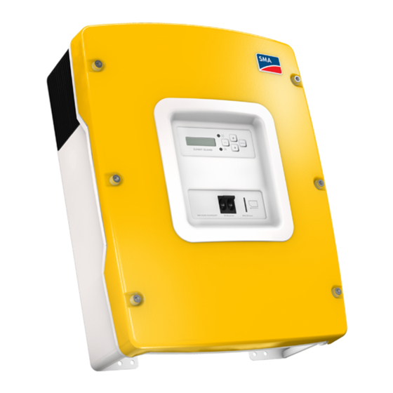
The Sunny Island 5048U SMA America, LLC 2.2 At a Glance The following figure provides an overview of all control elements and connections of the Sunny Island: SI5048U-TUS121440 Technical Description... - Page 23 SMA America, LLC The Sunny Island 5048U Marker Description Display LEDs showing device operation Control buttons Slot for the SD card Opening for the additional connections area (insertion of the cables via conduits) Connection area for additional connections Opening for the additional connections area (insertion of the cables via conduits)
-
Page 24: Scope Of Delivery
The Sunny Island 5048U SMA America, LLC 2.3 Scope of Delivery Check the delivery for completeness. Check the packaging and the Sunny Island for externally visible damage. Contact your supplier in case of damage to the packaging. Contact your dealer if you find any damage on the Sunny Island or if there are parts missing in the delivery. -
Page 25: Required Tools And Resources
SMA America, LLC The Sunny Island 5048U Marker Number Designation M6x10 mm screws and locking washers for connecting the Sunny Island with the wall mounting bracket. Technical Description Test Report 4-pole print terminal for connecting the battery temperature sensor and current sensor... -
Page 26: Identifying The Sunny Island
The Sunny Island 5048U SMA America, LLC Material (not included in delivery) Cable ties Heat shrink tubing Hexagon bolts, ⁄ in. x 2 ⁄ in. (8 mm x 60 mm), washers Wall anchors for the wall mounting bracket (e.g. SX 10) 2.5 Identifying the Sunny Island... -
Page 27: Safety Instructions
SMA America, LLC Safety Instructions 3 Safety Instructions 3.1 Important Notes regarding Operation Follow all operating and safety instructions in this manual. If these instructions are ignored, a significant danger of injury or death arises and damage to the device, system or plant may also result. -
Page 28: Potential Hazards
Installation Altitude The Sunny Island has been designed for use at elevations of up to 9840 ft. (3000 m) above sea level. Contact SMA before using the device at elevations above 9840 ft. (3000 m). A performance loss of 0.5 % per 330 ft (100 m) is to be expected starting at an elevation of 6560 ft. - Page 29 SMA America, LLC Safety Instructions NOTICE! Destruction of the Sunny Island if installed in improper locations. The Sunny Island is only suited for indoor installation and corresponds to degree of protection NEMA 1 (IP30, or IP40 with inserted SD card).
-
Page 30: Assembly
Assembly SMA America, LLC 4 Assembly 4.1 Selecting the Mounting Location DANGER Danger of death if installed in improper locations. Death or serious burns. Despite careful construction, a fire can occur with electrical devices. • Do not mount the Sunny Island on flammable construction materials. - Page 31 SMA America, LLC Assembly Observe the following conditions during mounting: • The mounting method and mounting location must be suitable for the weight and dimensions of the Sunny Island. • Mount on a solid surface. • The installation location must be accessible at all times.
- Page 32 Assembly SMA America, LLC • Maintain the minimum distances to walls, other devices and objects as represented in the illustration. In order to maintain sufficient ventilation, when installing the Sunny Island a minimum clearance of 12 in. (30 cm) at the sides and top must be maintained.
-
Page 33: Mounting The Sunny Island With A Wall Mounting Bracket
SMA America, LLC Assembly 4.2 Mounting the Sunny Island with a Wall Mounting Bracket Technical Description SI5048U-TUS121440... -
Page 34: Mounting The Sunny Island On A Stone Wall
Assembly SMA America, LLC 4.2.1 Mounting the Sunny Island on a Stone Wall CAUTION Risk of injury due to the Sunny Island falling. Physical injury (fractures or crushing) and damage to the Sunny Island. • If mounting onto a stone wall, ensure that the wall can carry the weight of the Sunny Island. - Page 35 SMA America, LLC Assembly 5. Attach the Sunny Island to the wall mounting bracket. 6. Screw the Sunny Island to the wall mounting bracket on both sides using the screws (M6x10) provided. Tighten the screws clockwise. 7. Make sure that the device is securely in place.
-
Page 36: Mounting The Sunny Island Using Wall Studs
Assembly SMA America, LLC 4.2.2 Mounting the Sunny Island Using Wall Studs CAUTION Risk of injury due to the Sunny Island falling. Physical injury (fractures or crushing) and damage to the Sunny Island. • If mounting onto a stone wall, ensure that the wall can carry the weight of the Sunny Island. -
Page 37: Opening And Closing
SMA America, LLC Opening and Closing 5 Opening and Closing The enclosure of the Sunny Island has a removable lid. Remove the enclosure lid only when installing the device or for required maintenance or repair work. 5.1 Opening the Sunny Island 1. Stop the Sunny Island (see section 9.2 ”Stopping (Standby)” (page 73)). -
Page 38: Closing The Sunny Island
Opening and Closing SMA America, LLC 5.2 Closing the Sunny Island DANGER Electric shock due to live enclosure lid. Death or serious injuries. • Fasten the washers for all 6 screws with the toothing facing toward the enclosure lid. Tighten the Screws with Washers in the Correct Order Tighten the screws with 53 in-lbs (6 Nm) torque in the order shown. -
Page 39: Electrical Connection
SMA America, LLC Electrical Connection 6 Electrical Connection All cables are fed through the openings on the bottom side of the device (see next illustration) and connected to the appropriate connection terminals on the Sunny Island. Use cable ducts to install the cables on the DC and AC sides on the Sunny Island. The cable ducts guarantee a dust-free and waterproof installation of the cables in the enclosure and also provide strain relief for the cable connection. - Page 40 Electrical Connection SMA America, LLC Terminal Bolt clamp Wire Size Wire type AC connections 22 in-lbs. − 39 in-lbs. AWG 4 (25 mm²) Only use copper (2.5 Nm − 4.5 Nm) conductors. These must be rated for at least 167°F (75 °C). Do not use fine-wire strands.
-
Page 41: Grounding
SMA America, LLC Electrical Connection 6.1 Grounding WARNING Risk of lethal electric shock. • Fuse the sub‑distribution of the generator or the power distribution grid at input AC2 of the Sunny Island with an overcurrent protective device (Branch Circuit Protection). • Ensure that the overcurrent protective device complies with the specifications of the ®... - Page 42 ☑ The grounding conductor is connected. Calculating the cross‑section of a grounding conductor SMA cannot state generally valid values for the cross‑section of the grounding conductor required for the external grounding of the battery. The cable dimensions depend on the type and size of the battery connected, the external fuse (DC side) and the material used in the grounding cable.
-
Page 43: Dc Terminal
Choice of Cable Cross-sections SMA recommends choosing cable cross-sections greater than those given by NEC 250.122 in the case of cable lengths exceeding 32.8 ft (10 m). Example of Cable Sizing With a 48 V battery voltage and an outgoing AC power of 5 000 W, a current of up to 140 A flows... -
Page 44: Cable Protection
Electrical Connection SMA America, LLC The current flowing through the battery cable causes a power loss and a drop in voltage with every meter of plain battery cable. You can use the following table to find the power loss and voltage drop associated with different cable cross-sections. -
Page 45: Connecting The Sunny Island To The Dc Side
SMA America, LLC Electrical Connection 6.2.4 Connecting the Sunny Island to the DC side WARNING Risk of lethal electric shock. • Connect the external fuse and the battery cable to the battery only after all installation work has been completed. Requirements •... -
Page 46: Ac Connection
Electrical Connection SMA America, LLC DC Cables Do not connect any other components to the DC cables. Other components must be connected directly to the battery via separate cables. The Sunny Island has a MAX DC terminal rated for 2x#2/0 for Pos, Neg and PE. - Page 47 SMA America, LLC Electrical Connection Connection in a Split‑Phase System In a split‑phase system, connect the master to phase L1 and the slave 1 to phase L2 (see section 2.2 ”At a Glance” (page 22)). Double Split‑Phase System In a double split‑phase system, connect the master and slave 2 to phase L1.
-
Page 48: Ac2 (Generator/Grid)
Electrical Connection SMA America, LLC 5. Insert PE into the terminal labeled "AC1 Loads/Sunny Boys" and tighten the fastening screw with a torque of 22 in-lbs. − 39 in-lbs. (2.5 Nm − 4.5 Nm). Use a torque wrench with flat-head screwdriver bit SZS 1.0 x 6.5. - Page 49 SMA America, LLC Electrical Connection Additional Fuses in the System If there are no additional fuses installed between the generator or power distribution grid and the Sunny Island, the Sunny Island knows whether it has a connection to the power distribution grid/to the generator.
-
Page 50: Additional Connections
Electrical Connection SMA America, LLC 6.4 Additional Connections For installing the connections described below, feed the cables through the specified holes in the cable insert. Plugs for sealing the RJ45 communication cable for internal and external communication are provided in the rubber terminal block upon delivery. Combining plugs allows you to establish up to 4 cable entries (2 plugs without entry, 1 with 1 entry and 2 with 2 entries). - Page 51 SMA America, LLC Electrical Connection NOTICE Destruction of the battery through deep discharge as a result of the installation of an unsuitable battery temperature sensor. • Only use the battery temperature sensor included in the scope of delivery. • Do not drill holes into the battery to install the battery temperature sensor.
-
Page 52: Battery Current Sensor
Electrical Connection SMA America, LLC 6.4.2 Battery Current Sensor In addition to the internal measurement, the Sunny Island provides the possibility to measure the battery current via a shunt. You need this function if you intend to operate additional DC generators and DC loads in your off-grid power system. -
Page 53: Communication For Multi-Device Connection
SMA America, LLC Electrical Connection Use Cables of Intrinsically Safe Circuits Use cables of intrinsically safe circuits for the connection of battery current sensors. ”Intrinsically safe” means here that the cable is double-insulated and that the wire melts but the insulation remains intact in the event of a short-circuit. In addition, the cable is not combustible. - Page 54 Electrical Connection SMA America, LLC 5. Connect the Sunny Island master to the slave. Number of slaves Connection Procedure 1 slave • Take the RJ45 cable leading away from the master, introduce it into the Sunny Island slave and plug it into the ”ComSyncIn”...
-
Page 55: Multi-Function Relay 1 And 2
SMA America, LLC Electrical Connection 6.4.4 Multi-function Relay 1 and 2 The Sunny Island offers you several options for the control of internal and external processes. For this purpose, two multi-function relays are integrated into the Sunny Island to which you can assign functions using the ”241.01 Rly1Op”... - Page 56 Electrical Connection SMA America, LLC 4. Connect the wires to the 3-pole print terminals included in delivery. The pins have the following meaning: – NC: normally closed (when the Sunny Island is off, the relay is closed) – C: Contact (operating contact) –...
- Page 57 SMA America, LLC Electrical Connection Power Contactor for Load Shedding The Sunny Island can automatically switch off loads to protect the batteries from deep discharge. To do this, an external (AC or DC) power contactor must be installed between the Sunny Island and the loads (see section 12.1 ”Load Shedding”...
-
Page 58: Batvtgout Power Supply
Electrical Connection SMA America, LLC Generator start The Sunny Island can control generators. The Sunny Island directly supports generators that can be started/stopped using a single contact. Default Setting of the Relays By default, relay 1 is set to the generator start function ”AutoGn” and relay 2 is set to the load shed function ”AutoLodSoc”. -
Page 59: Digin Digital Input
SMA America, LLC Electrical Connection 6.4.6 DigIn Digital Input The DigIn connection is used as a digital input for external electrical sources. Range of the Input Voltage at the DigIn Input There can be 5 V − 63 V at the DigIn digital input. -
Page 60: Interface For External Communication
SMA America, LLC 6.5 Interface for External Communication You can connect communication devices from SMA Solar Technology (e.g., Sunny Boy Control, Sunny WebBox) or a PC with the appropriate software to a communication interface. A detailed wiring diagram can be found in the communication device manual, of the software or on the Internet at www.SMA-America.com. - Page 61 SMA America, LLC Electrical Connection Marker Description Slot for communication interface Cable route Enclosure entry in the base of the Sunny Island 2. Feed the cable from the outside through the cable entry (C) inside the Sunny Island. 3. Plug the cable into the ”ComSmaIn” socket.
- Page 62 Electrical Connection SMA America, LLC Connecting Sunny Island to Sunny Boy and Sunny WebBox with one RS485 cable Connecting Sunny Island to Sunny Boy and Sunny WebBox with seperate RS485 cables Data Transmission Speed The Sunny Island can be operated at different data transmission rates to communicate with external devices.
-
Page 63: Control Elements
SMA America, LLC Control Elements 7 Control Elements In order to commission the Sunny Island, you should familiarize yourself with its operation beforehand. The individual control elements can be seen in the following figure. Marker Description Display Red LED Green LED... -
Page 64: Display Messages
Control Elements SMA America, LLC 7.1 Display Messages The display of the Sunny Island has two lines, each with 16 characters. Meaning of the symbols You will find information on the meaning of the individual symbols in section 10.6 ”Display Messages (Overview)” (page 87). -
Page 65: Buttons
SMA America, LLC Control Elements 7.3 Buttons The table explains the functions of the buttons on the Sunny Island: Button Function cancels the selected function answers NO navigates one menu level higher stops device (when held pressed down) navigates up one list element, increases data value... -
Page 66: Initial Start-Up
Always save data Always use the SD card to save data and events. In case of a failure SMA can thus help you quickly. • Always leave the SD card plugged in the Sunny Island. - Page 67 If you have a system with more than 1 Sunny Island, you must take the following measures: • Configure the Sunny Island with the latest firmware version as master or install the latest firmware version in the master (see www.SMA‑America.com). The master updates the firmware of the slaves once the off‑grid system is started.
- Page 68 Initial Start-up SMA America, LLC 3. Use ”New System” to set the following parameters: – Device type (master, slave1, slave2, slave3) Systems with One Sunny Island If only one Sunny Island is used in the system, the device type is set to ”master” and is not displayed.
- Page 69 SMA America, LLC Initial Start-up – External power supply unit Value in variable Explanation PvOnly Off Grid, no grid, no generator Off Grid with Generator Grid Grid Backup GenGrid Grid Backup with Generator GenGrid: – Maximum generator current (0 A - 224 A), default setting: ”30 A”...
-
Page 70: Connecting The Battery Current Sensor
Initial Start-up SMA America, LLC 8.3 Connecting the Battery Current Sensor If you have installed a battery current sensor in your system you must calibrate the device's internal offset. To do this, proceed as follows: 1. Put the Sunny Island in standby, as described in section 9.2 ”Stopping (Standby)” (page 73). - Page 71 SMA America, LLC Initial Start-up 6. Check the offset error: ”120.06 TotBatCur” should be around zero. 7. Connect the battery current sensor cables correctly again, as shown in the figure. Make sure the wires have the correct polarity when doing this.
-
Page 72: Switching On And Off
Switching On and Off SMA America, LLC 9 Switching On and Off 9.1 Switching on Systems with Several Sunny Island Inverters Switch on the slaves before switching on the master. To do this, proceed as follows. 1. Check the following requirements: – correct electrical connections –... -
Page 73: Stopping (Standby)
SMA America, LLC Switching On and Off ☑ The Sunny Island skips the QCG and the notification shown here is displayed. 4. Press <Enter> and keep pressed. ☑ Process bars is shown in the display. ☑ On a slave, the notification displayed here is shown until the master is started. -
Page 74: Switching Off
Switching On and Off SMA America, LLC 9.3 Switching off To switch off the Sunny Island, proceed as follows: ”Disconnection sequence” Only with the sequence shown here can you ensure that all internal counter positions/ values are saved. 1. Stop the Sunny Island as described in section 9.2 ”Stopping (Standby)” (page 73). - Page 75 SMA America, LLC Switching On and Off To reactivate the Sunny Island after it has switched off due to a battery being too deeply discharged, proceed as follows: 1. Switch the Sunny Island's DC circuit breaker to the ”OFF” position.
-
Page 76: Operation
Operation SMA America, LLC 10 Operation The main menu consists of a ”Home Screen” and the main menu entries, which split up into the different menu levels. Operating modes are displayed on the Home Screen, e.g., the current operating mode, performance, etc. (see section 10.6 ”Display Messages (Overview)” (page 87)). -
Page 77: Menu Structure
SMA America, LLC Operation Single Point of Operation Single Point of Operation also means that all log data, including the slave log data, is saved at the master device on the SD card. Messages Messages can be displayed at any time while the device is in operation and they have priority over the Home Screen display. - Page 78 Operation SMA America, LLC Overview of the Menu Structure SI5048U-TUS121440 Technical Description...
- Page 79 SMA America, LLC Operation 100# Meters - Display values: In this main menu you will find the display values for the following components of the off-grid power system: • 110# Meter Inverter ‒ Sunny Island • 120# Battery Meters ‒ Battery •...
-
Page 80: Changing Parameters
Operation SMA America, LLC 600# Direct Access - Direct access to the parameters This is a main menu that gives you direct access to the settings and display values (see section 10.3 ”Direct Access (to the parameters)” (page 81)). 10.2 Changing Parameters Using the up and down arrow buttons, you navigate through a selected menu to view or change a parameter, for example. -
Page 81: Direct Access (To The Parameters)
SMA America, LLC Operation 10.3 Direct Access (to the parameters) The ”600# Direct Access” menu gives you direct access to the selected parameter using the parameter name or number. Via the Select Name sub-menu, you have direct access to the following functions: •... - Page 82 Operation SMA America, LLC Bat 1 (Battery Value 1) Marker Description Compact Meter name Present battery charge state (BatSoc) Estimated error of the charge state (BatSocErr) Total battery current of the cluster (TotBatCur) Battery temperature (BatTmp) Bat 2 (Battery Value 2)
- Page 83 SMA America, LLC Operation Inv (AC values of inverter) Marker Description Compact Meter name Present voltage at the inverter (InvVtg) Present frequency at the inverter (InvFrq) Present active power of the inverter (InvPwrAt) Present reactive power at the inverter (InvPwrPt)
- Page 84 Operation SMA America, LLC Ext (AC values of external source) Marker Description Compact Meter name Voltage of the external source (ExtVtg) Frequency of the external source (ExtFrq) Active power of the external source (ExtPwrAt) Reactive power of the external source (ExtPwrPt)
-
Page 85: Entering The Installer Password
Do not provide the following information for entering the installer password to unauthorized persons. Illegal provision of this information to other persons will lead to invalidation of all warranties by SMA. Enter Password The Sunny Island allows you to enter the password not only in standby, but also during operation. - Page 86 Operation SMA America, LLC Password = Sum of digits of the operating hours. Proceed as follows to enter the installer password from the ”Home Screen”: 1. Keep pressing the down arrow button until you reach the menu ”200# Settings”. 2. Press <ENTER>.
-
Page 87: Display Messages (Overview)
SMA America, LLC Operation 10.6 Display Messages (Overview) The display has two lines, each with 16 characters. The first line shows the menu number and the menu name, or the name of the parameter where applicable. The menu name is supplemented or the added text is displayed (e.g., parameter value) in the lower line, if required. - Page 88 Operation SMA America, LLC • Active charging process Situation-Dependent Value Display The display shows only values that are relevant in the actual system status. If there is no generator connected, no generator values are displayed. Messages on the Slave Devices On the slave devices, the upper line of the display shows the bar graph for output power or charging power.
- Page 89 SMA America, LLC Operation Symbol Meaning Status of the external source is displayed (at position E): The maximum admissible generator reverse power was exceeded; the Sunny Island has disconnected the generator from the off-grid power system. Request reason ”Battery”: The generator has been requested as a result of the battery charge level.
-
Page 90: Parameter Display
Operation SMA America, LLC Stopping the Generator Manually If the generator has been manually stopped, no generator status information is displayed. The field remains empty in this case. Indications of a Warning If faults occur, the device switches into standby mode and shows the fault on the display. -
Page 91: Display Of Warnings And Failures
SMA America, LLC Operation 10.9 Display of Warnings and Failures The Sunny Island can display a list of errors and warnings: The running number (quantity) of the errors is on the upper line; the time and date display changes in 2-second intervals. On the lower line are the number of the error and the corresponding error short text. -
Page 92: Archiving Data On An Sd Card
3 figures after the dot. Type of Memory Card SMA recommends using MMC/SD cards manufactured by Transcend. If you use a memory card from another manufacturer, check whether the card is FAT16-formatted. If necessary, format the card. Be aware that data stored on the card will be lost. - Page 93 Statistical values of the battery. These values are saved every day at 10:00 p.m. batstat.sma Internal data from SMA si.ccf System information from Sunny Island. ”BOOTEX.LOG” File The ”BOOTEX.LOG” file is not necessarily on the card. It is created depending on the operating system used (e.g., Windows XP or Windows2000).
- Page 94 SMA America, LLC • Loads Always Save Data Always use the SD card to save data and events. In case of a failure SMA can thus help you quickly. 1. In the event of a fault contact the SMA Service Line.
-
Page 95: Inserting The Sd Card
SMA America, LLC Archiving Data on an SD Card 11.1 Inserting the SD Card NOTICE Electrostatic discharge when inserting the SD card. Electrostatic discharges can damage the Sunny Island components. • Ground yourself before you insert or remove the SD card from the Sunny Island enclosure. -
Page 96: Removing The Sd Card
Archiving Data on an SD Card SMA America, LLC 11.2 Removing the SD Card To ensure that all log data is saved upon deactivation, write all as-yet unsaved data from the buffer to the SD card by using the parameter ”550.03 CardFunc” with the option ”ForcedWrite”. -
Page 97: Status Messages
SMA America, LLC Archiving Data on an SD Card 11.5 Status Messages Using the ”312.07 CardStt” parameter, you can request the status of your SD card: Display Description The SD card is deactivated. The SD card is activated. The memory capacity of your SD card has been exceeded. -
Page 98: Updating The Firmware
1. Create a security copy of the existing parameter lists (see section 11.3 ”Saving and Loading Parameters” (page 96)). 2. Download the current version of the firmware from the Internet at www.SMA-America.com. 3. Copy the ”UPDATE.BIN” file onto the SD card. 4. Set the master device to standby. - Page 99 SMA America, LLC Archiving Data on an SD Card Starting QCG If you have carried out a firmware update in which the number before the dot in the firmware version has changed, it is advisable to start QCG and to perform all settings anew.
- Page 100 Archiving Data on an SD Card SMA America, LLC Display message Message shown by Explanation ⋮ Master Update of slaves starts. ⋮ Master Update of slaves Update Slaves... running. ⋮ Master Update of master finished. ⋮ Slave Update of slaves finished.
-
Page 101: Additional Functions
SMA America, LLC Additional Functions 12 Additional Functions 12.1 Load Shedding If, over an extended period, the loads connected to the Sunny Island use more energy than that which the generators connected produce, the battery can deeply discharge. The Sunny Island shuts down automatically if the state of charge of the battery is too low. - Page 102 Additional Functions SMA America, LLC Soc [%] Lod1SocTm1 Stp Lod1SocTm2 Stp Lod1SocTm2 Stp Lod1SocTm1 Str Lod1SocTm2 Str Lod1SocTm2 Str Lod1Tm1Str Lod1Tm2Str The graphic shows an example for the settings that minimize the load shedding function at night. From 6:00 a.m. to 10:00 p.m. the load shedding is activated for a charge state (SOC) of 40 %, at nighttime (from 10:00 p.m.
-
Page 103: Sleep Mode
SMA America, LLC Additional Functions • The battery state of charge during the t2 interval, the recognition of which will lead to the load- shedding function being started: Parameter ”242.03 Lod1SocTm2Str”. • The battery state of charge during the t2 interval, the recognition of which will lead to the load- shedding function being stopped: Parameter ”242.04 Lod1SocTm2Stp”. -
Page 104: Automatic Frequency Control (Afc)
Additional Functions SMA America, LLC Display of messages Messages can be displayed at any time while the device is in operation and they have priority over the Home Screen display. 12.6 Automatic Frequency Control (AFC) Clocks that depend on the stability of the grid frequency for their accuracy become increasingly inaccurate when there are constant frequency deviations. -
Page 105: Battery Management
SMA America, LLC Battery Management 13 Battery Management The battery management of the Sunny Island supports the following three battery types ("221.01 BatTyp" parameter): Flooded Lead Acid: Closed lead acid batteries with liquid electrolyte in all standard designs available on the market (grid plate, tubular plate, small, large, etc.). -
Page 106: Start Options
Battery Management SMA America, LLC NOTICE Destruction of the battery through deep discharge. If the battery temperature sensor is defective or missing, the Sunny Island continues to run, assuming a battery temperature of 104 °F (40 °C). This can lead to a deep discharge of the battery in the long run. -
Page 107: Charge Control
SMA America, LLC Battery Management The battery's state of health (display value ”320.01 Soh”) is a measurement of the present useable capacity expressed as a percentage relative to the nominal capacity. 100 % means that the entire nominal capacity can be used. 50 % means that only half of the original nominal battery capacity can be used. - Page 108 Battery Management SMA America, LLC a defined period of time (”222.02 — 222.04”, AptTmBoost or AptTmFul or AptTmEqu” parameters). For this charging phase, the Sunny Island automatically selects one of three possible charging methods (boost, full, equalizing) which are described in detail in sections 13.4.1 ”Boost Charge”...
-
Page 109: Boost Charge
SMA America, LLC Battery Management The charging capability of batteries is highly dependent on the battery temperature. For temperatures < 77 °F (25 °C), the charging voltage must be slightly increased, and for temperatures > 77 °F (25 °C) it must be slightly decreased. This is necessary to prevent overcharging and deep discharge reliably at any battery temperature. -
Page 110: Equalization Charge
Battery Management SMA America, LLC Procedures Parallel to the Full Charge Any parallel procedures causing the generator to stop during the full charging process are not taken into account until the charging process is completed. 13.4.3 Equalization Charge A battery bank consists of many individual battery cells connected in series which all behave slightly different. -
Page 111: Silent Mode
SMA America, LLC Battery Management 13.4.5 Silent Mode In addition to the float charge, the silent mode can be used (”224.01 SilentEna” parameter), only when operating on the public grid in the operation type ”GridCharge”. The main purpose of the silent mode is to save energy by switching from charge mode to standby mode in utility backup systems where the Sunny Island is predominantly in float charge. - Page 112 Battery Management SMA America, LLC Level 2: The second level of the battery preservation mode ensures that the Sunny Island is started regularly every two hours only in the time period during which energy supply is expected, and that it attempts to charge the battery from the AC side.
-
Page 113: Battery Diagnostics
SMA America, LLC Battery Management 13.6 Battery Diagnostics The ”320# Battery Diagnosis” menu displays several values that provide information on the past operational behavior of the battery. These values are helpful in checking the efficiency of the set parameters and in viewing the typical operating conditions of the battery (see section 19.3 ”Diagnosis (300#)”... -
Page 114: Connecting External Sources
Connecting External Sources SMA America, LLC 14 Connecting External Sources The Sunny Island supports the integration of external energy sources. Here a distinction is made between the integration of a generator and the integration of the public grid. Both the generator as well as the public grid are integrated through the AC2 connection of the Sunny Island. - Page 115 SMA America, LLC Connecting External Sources Sunny Island connected in parallel to a 120V generator Sunny Island with a split-phase connection to a 240 V generator Generally the internal transfer relays of the slaves close only if the internal relay of the master is closed.
-
Page 116: Generator Start Options
Connecting External Sources SMA America, LLC Cable Length and Cable Cross-section Use the same cable lengths and cable cross-sections when installing the Sunny Island inverters with the generator. 14.1.2 Generator Start Options The Sunny Island supports the following options for starting the generator which can be set in standby mode with the ”234.07 GnStrMod”... - Page 117 SMA America, LLC Connecting External Sources GenReq Signal The GnReq signal (see section 15 ”Relays” (page 136)) is set for signaling the generator request and can thus be used as an alarm contact (in this case: a bulb). If no request is pending, the signal is reset.
-
Page 118: Generator Operation
Connecting External Sources SMA America, LLC The following figure shows the wiring for a generator capable of autostart: If the generator is started manually in this operating mode, the Sunny Island detects the running generator and connects it once the warm-up time has expired. If the generator is externally stopped, this is detected, the generator is disconnected and the off-grid power system is continued to be supplied. - Page 119 SMA America, LLC Connecting External Sources Start: Manual generator start – the generator runs ”continuously” until stopped. The generator can only be manually stopped. Run1h: Operation for one hour. Once the lockout time has expired, the transition back into automatic mode follows.
-
Page 120: Automatic Generator Operation
Connecting External Sources SMA America, LLC 14.1.5 Automatic Generator Operation In automatic operating mode (”235.01 GnAutoEna” parameter), the Sunny Island automatically defines the settings (as a function of battery charge state or loads) to determine when the generator starts and how long it runs. The automatic operating mode is activated using GnAutoEna = On (default). - Page 121 SMA America, LLC Connecting External Sources Reaching the floating charge process If the float charging process (see section 13.4 ”Charge Control” (page 107)) is activated before the cutoff limit (GnSocTm1Stp or GnSocTm2Stp) is reached, the generator request is disabled again. If a full or equalization charge is active, the generator is only stopped after this charge is completed and not when ”235.04 GnSocTm1Stp”...
-
Page 122: Limits And Power Adjustment
Connecting External Sources SMA America, LLC Generator Interface ”234.07 GnSrtMod” = Manual; Generator Request Via Sunny Island Generator is requested via Sunny Island Manual generator start ”Generator is running” detected, beginning of warm-up phase Warm-up phase is completed, connection Generator current limit... - Page 123 SMA America, LLC Connecting External Sources The voltage and frequency limits are monitored in phases. At least the phase on the master device must comply with the limits defined for connecting the generator. If the limits are not maintained, slave devices, where applicable, connect or disconnect individually.
-
Page 124: Run Times
Connecting External Sources SMA America, LLC 14.1.7 Run Times If the generator is started (or the Sunny Island detects an external generator start), the warm-up phase starts. If, during this time, the voltage or frequency detected is not within the permissible range, the warm-up time begins again. -
Page 125: Operation In Conjunction With Pv Inverters
SMA America, LLC Connecting External Sources • Remaining stop time after the shut-off delay time has expired (Lock) • Remaining time in the error state (Fail) • Remaining time in the locked error state (FailLock) 14.1.8 Operation in Conjunction with PV Inverters NOTICE Wrong system design may lead to exceeding the maximum AC power of the PV inverters. -
Page 126: Stopping The Sunny Island
Connecting External Sources SMA America, LLC Generators with a Manual Start Option Generators with the ”manual” start option can generally only be started and stopped at the generator. Generator Start Prevented If the generator start is to be disabled after a manual stop, this must be performed by setting the ”235.01 GnAutoEna”... -
Page 127: Grid
SMA America, LLC Connecting External Sources 14.2 Grid The Sunny Island supports the operation of grid backup systems. Here, a distinction is made between two main states: either a main power grid and an off-grid power system are connected or a main power grid and an off-grid power system are disconnected. -
Page 128: Grid Reconnection
Connecting External Sources SMA America, LLC Whenever this information is missing (in case of maintenance or a failure) the Sunny Boy inverters switch from the ”OffGrid” to the ”grid-tied” setting and take over the Anti-Islanding function. This ensures that an Anti-Islanding is active at all times according to UL1741 when feeding into the public grid. - Page 129 SMA America, LLC Connecting External Sources Grid as generator: Charging the Sunny Island via the grid in order to avoid deep discharge Manual grid start deactivates settings for automatic grid start Via the ”560.01 GdManStr” parameter you can define whether the grid is to be connected or not.
- Page 130 Connecting External Sources SMA America, LLC Grid as generator: connecting the grid as soon as the loads request high power from the Sunny Island You can configure the Sunny Island in such way that it automatically connects to the grid, as soon as the connected loads request high power from the Sunny Island.
- Page 131 SMA America, LLC Connecting External Sources The following illustration shows the energy flow direction for net metering and energy consumption of public grid. Technical Description SI5048U-TUS121440...
-
Page 132: Grid Failure
Connecting External Sources SMA America, LLC 14.2.7 Grid Failure A grid fault is characterized by the voltage or frequency being outside of the permissible limits (see section 14.2.5 ”Grid Reconnection” (page 128)) or the main power grid being disconnected. In this case, the time limits are relevant: Smaller deviations are permitted for longer than large deviations (see section 14.2.1 ”Voltage and Frequency Limits”... -
Page 133: Limits And Power Adjustment
SMA America, LLC Connecting External Sources 14.2.9 Limits and Power Adjustment The Sunny Island draws power from the public grid during each phase using the current specified via the ”232.03 GdCurNom” parameter. The power that is not directly used by the loads flows into the battery for charging. -
Page 134: Generator And Grid
• If a manual switch is installed, leave the switch in off-position for at least 5 seconds before switching to the new position. • Refer to the download area at www.SMA-America.com for further information on how to install a switch for connecting the Sunny Island to the power distribution grid and to a generator. - Page 135 SMA America, LLC Connecting External Sources 3. Connect the positive pole of the BatVtgOut connection to the second contact of the same auxiliary contact on the transfer switch. An auxiliary contact is used because the Sunny Island must ”know” whether it is connected to the public grid or whether it must manage a diesel generator.
-
Page 136: Relays
Relays SMA America, LLC 15 Relays The Sunny Island offers you several options for the control of internal and external processes. For this purpose, two relays are integrated into the device with which you can assign functions using the parameters ”241.01 Rly1Op” and ”241.02 Rly2Op”. - Page 137 SMA America, LLC Relays Function/Setting Meaning Function description GdOn Public grid Relay switching when public grid is available and connected. Error Error Sunny Island has a fault; in case of fault, contact is open (relay is deactivated). Warn Warning The Sunny Island has warning pending.
-
Page 138: Multicluster Operation
Multicluster Operation SMA America, LLC 16 Multicluster Operation 16.1 Communication between the Sunny Islands For increased output, up to four Sunny Island clusters can be interconnected to form a Multicluster system. For such a system, the Multicluster Box for Sunny Island 4548-US/5048-US/6048-US (MCB12-U) is required. - Page 139 SMA America, LLC Multicluster Operation RJ45 Cable The RJ45 communication cable is a standard Cat5e-FTP cable (simple shielding), with gold contacts. Each Multicluster Piggy-Back (MC-PB) is delivered with one yellow and one gray RJ45 communication cable and two plugs (termination resistors).
-
Page 140: Initial Commissioning Of The Multicluster System
Multicluster Operation SMA America, LLC Main-Cluster Extension-Cluster 1 Extension-Cluster 2 Master Slave 1 Slave 2 Master Slave 1 Slave 2 Master Slave 1 Slave 2 16.2 Initial Commissioning of the Multicluster System 1. Carry out steps 1 - 3 in section 8.2 ”Starting the Quick Configuration Guide (QCG)”... -
Page 141: Switching A Multicluster System On And Off
SMA America, LLC Multicluster Operation 16.3 Switching a Multicluster System On and Off 16.3.1 Activation / Startup Switching on a Multicluster system can only take place at the master of the main cluster. The extension clusters will be started automatically after starting the main cluster. A requirement is that the DC circuit breakers of all Sunny Island inverters in the extension cluster are set to ”ON”. -
Page 142: Generator Operation
Multicluster Operation SMA America, LLC 16.4 Generator Operation The main master's generator request comprises its own request (based on SOC, time, etc.) and possible requests from one or more extension clusters. The generator remains in a requested state as long as a request is present. -
Page 143: Automatic Frequency Control (Afc)
SMA America, LLC Multicluster Operation 16.7 Automatic Frequency Control (AFC) In Multicluster operation, automatic frequency control (AFC) can only be activated at the main master. This function is activated using the ”250.11 AfraEna” parameter. 16.8 Firmware Update Stopping the Sunny Island It is recommended to stop the entire cluster network, and to deactivate the loads insofar as this is possible. -
Page 144: Emergency Generator Load Support
Multicluster Operation SMA America, LLC 16.11 Emergency generator load support If a Multicluster system fails, manual operation via the generator is possible. For this purpose, the generator must be started manually, directly at the generator. As soon as a voltage is present, the Multicluster Box connects the generator through to the loads, without there being a Sunny Island in operation. -
Page 145: Pv Inverter
SMA America, LLC PV Inverter 17 PV Inverter The following section provides information for connecting and configuring the Sunny Boy inverter in off-grid power systems. The Sunny Island along with the Sunny Boy inverters are optimized to work in backup (grid-tied) as well as in off-grid applications. -
Page 146: Setting The Off-Grid Parameters (Sunny Boy)
Install one of these three variants: • Sunny WebBox • Sunny Boy Control • PC/laptop with Sunny Data Control software and a service cable for data transmission (SMA order number: "USBPBS‑11" ‑ USB service interface) 17.4 Sunny Boy Parameter Settings Grid‑tied Inverter... -
Page 147: Frequency Shift Power Control (Fspc)
SMA America, LLC PV Inverter Stand‑alone grid with or without generator Inverter Parameters Setting Sunny Boy 3000‑US Default OffGrid Sunny Boy 3800‑US BackupMode Sunny Boy 4000‑US Sunny Boy 5000‑US Sunny Boy 6000‑US Sunny Boy 7000‑US Sunny Boy 8000‑US The "OffGrid" parameter setting automatically sets the following Sunny Boy parameters to the values... - Page 148 PV Inverter SMA America, LLC If Sunny Boy inverters are connected to the AC side of the off-grid power system, the Sunny Island must be able to limit their output power. This situation can occur when, e.g., the Sunny Island battery is fully charged and the (solar) power available from the PV generator exceeds the power required by the connected loads.
-
Page 149: Maintenance And Care
Dispose of the Sunny Island at the end of its service life in accordance with the disposal regulations for electronic waste which apply at the installation site at that time. Alternatively, send the devices back to SMA with shipping paid by sender, and labeled ”FOR DISPOSAL” (section 24 ”Contact” (page 226). -
Page 150: Parameter Lists
Only parameters in the menu branches ”200 Settings” and ”500 Operation” can be changed. All other values are only displayed on the Sunny Island 5048-US display. All menu items that can only be changed after entering the installer password are shaded in gray in the following tables. - Page 151 SMA America, LLC Parameter lists No. Name Description Display value Explanation Plain text (No.) InvPwrRt Reactive power of the Sunny Island in kVAr Rly1Stt State of relay 1 Relay open Relay closed Rly2Stt State of relay 2 Relay open Relay closed #113 Inverter Slave1 Meters No.
- Page 152 Parameter lists SMA America, LLC #114 Inverter Slave2 Meters No. Name Description Display value Explanation InvOpSttSlv2 Operating mode of Standby Standby the Sunny Island In operation slave 2 Error Error Startup Transfer standby > operation InvPwrAtSlv2 Effective power of the Sunny Island...
- Page 153 SMA America, LLC Parameter lists #115 Inverter Slave3 Meters No. Name Description Display value Explanation InvOpSttSlv3 Operating mode of Standby Standby the Sunny Island In operation slave 3 Error Error Startup Transfer standby > operation InvPwrAtSlv3 Effective power of the Sunny Island...
-
Page 154: Battery Meters (120#)
Parameter lists SMA America, LLC 19.1.2 Battery Meters (120#) No. Name Description Display value Explanation Plain text (No.) BatSoc Present battery charge state (SOC) in % BatVtg Battery voltage in V BatChrgVtg Charging voltage target value in V AptTmRmg Remaining absorption time in... -
Page 155: External Meters (130#)
SMA America, LLC Parameter lists 19.1.3 External Meters (130#) #131 Total Meters No. Name Description TotExtPwrAt Total active power of the external source in kW TotExtCur Total current of the external source in A TotExtPwrRt Total reactive power in kVAr TotLodPwr... - Page 156 Parameter lists SMA America, LLC No. Name Description Display value Explanation Plain text (No.) GnRmgTm Minimum remaining generator run time. Displayed in hours, minutes and seconds. GnRnStt Generator run state Off (1) that is detected by On (2) Sunny Island master.
-
Page 157: Charge Controller (140#) (Not Ul-Certified)
SMA America, LLC Parameter lists 137# Slave3 Meters No. Name Description ExtPwrAtSlv3 Active power of the external source slave 3 in kW ExtVtgSlv3 Voltage of the external source slave 3 in V ExtCurSlv3 Current of the external source slave 3 in A... - Page 158 Parameter lists SMA America, LLC 142# SIC40 1 No. Name Description Sic1EgyCntIn Energy of the first Sunny Island Charger in kWh Sic1TdyEgyCntIn Daily yield of the first Sunny Island Charger in kWh Sic1PvPwr PV power of the first Sunny Island Charger in W...
-
Page 159: Adjustable Parameters
SMA America, LLC Parameter lists 145# SIC40 4 No. Name Description Sic4EgyCntIn Energy of the fourth Sunny Island Charger in kWh Sic4TdyEgyCntIn Daily yield of the fourth Sunny Island Charger in kWh Sic4PvPwr PV power of the fourth Sunny Island Charger in W... -
Page 160: Battery Settings (220#)
Parameter lists SMA America, LLC 19.2.2 Battery Settings (220#) #221 Battery Property No. Name Description Value Explanation Default value BatTyp Battery type VRLA Valve regulated lead VRLA acid (AGM or GEL type) Flooded lead acid battery NiCd Nickel-cadmium battery BatCpyNom Nominal battery... - Page 161 SMA America, LLC Parameter lists #222 Battery Charge Mode No. Name Description Value Explanation Default value BatChrgCurMax Charging current of 10 A … 1200 A 1,200 A the battery AptTmBoost Absorption time for 1 min … 600 min VRLA 120 min boost charge 1 min …...
- Page 162 Parameter lists SMA America, LLC #223 Battery Protection No. Name Description Display value Default value BatPro1TmStr Starting time of the 22:00:00 battery- preservation mode (level 1) BatPro1TmStp End time of battery- 06:00:00 preservation mode (level 1) BatPro2TmStr Starting time of the...
-
Page 163: External Settings (230#)
SMA America, LLC Parameter lists 225# Battery Current Sensor No. Name Description Value Explanation Default value BatCurSnsTyp Battery current None No sensor is None sensor type connected. 60 mV Battery Current Sensor 60 mV 50 mV Battery Current Sensor 50 mV... - Page 164 Parameter lists SMA America, LLC 232# Grid Control No. Name Description Display value Explanation Default value GdVtgMin Minimum grid voltage 105.6 V GdVtgMax Maximum grid voltage 132 V GdCurNom Grid nominal current 30 A GdFrqNom Grid nominal frequency 60 Hz...
- Page 165 SMA America, LLC Parameter lists 233# Grid Start No. Name Description Display value Explanation Default value GdSocTm1Str SOC limit for 40 % switching on the grid for time 1 GdSocTm1Stp SOC limit for 80 % switching off the grid for time 1...
- Page 166 Parameter lists SMA America, LLC 234# Generator Control No. Name Description Value Explanation Default value GnVtgMin Minimum generator 80 V voltage GnVtgMax Maximum generator 150 V voltage GnCurNom Nominal generator 30 A current GnFrqNom Generator nominal 60 Hz frequency at nominal...
- Page 167 SMA America, LLC Parameter lists No. Name Description Value Explanation Default value GnAlSns AI sensitivity Normal Medium Medium Normal Normal High High 235# Generator Start No. Name Description Value Explanation Default value GnAutoEna Generator autostart Disable Enable GnAutoStr Number of autostarts...
- Page 168 Parameter lists SMA America, LLC No. Name Description Value Explanation Default value GnTmOpStrDt Starting date for time- 2010- controlled generator 01-01 operation GnTmOpStrTm Starting time for time- controlled generator operation in hours, minutes and seconds GnTmOpRnDur Running time for time-...
- Page 169 SMA America, LLC Parameter lists 236# CHP Control (Combined Heat and Power) No. Name Description Value Explanation Default value ChpOpTmMin Minimum run time 60 min of CHP plant ChpStpTmMin Minimum stop time 10 min of CHP plant ChpPwrMax Maximum power of...
- Page 170 Parameter lists SMA America, LLC No. Name Description Display value Explanation Default value ChpTm2Str Time 2 for CHP plant request in hours, minutes and seconds. Begin: Time 2, End: Time 1. ChpPwrEna Activate CHP plant Disable Disable Enable request based on...
-
Page 171: Relay Settings (240#)
SMA America, LLC Parameter lists 19.2.4 Relay Settings (240#) 241# Relay General No. Name Description Value Explanation Default value Rly1Op Function of relay 1 Off AutoGn AutoGn Generator request AutoLodExt External loadshedding AutoLod1Soc SOC1 Loadshedding AutoLod2Soc SOC2 Loadshedding Tmr1 Timer 1... - Page 172 Parameter lists SMA America, LLC No. Name Description Value Explanation Default value Rly2Op Function of relay 2 Off AutoLod AutoGn Generator request AutoLodExt External loadshedding AutoLod1Soc SOC1 Loadshedding AutoLod2Soc SOC2 Loadshedding Tmr1 Timer 1 Tmr2 Timer 2 AptPhs Absorption phase...
- Page 173 SMA America, LLC Parameter lists 242# Relay Load No. Name Description Value Explanation Default value Lod1SocTm1Str SOC limit for load 30 % shedding 1 start for Lod1SocTm1Stp SOC limit for load 50 % shedding 1 stop for Lod1SocTm2Str SOC limit for load...
- Page 174 Parameter lists SMA America, LLC No. Name Description Value Explanation Default value Lod2Tm1Str Time 1 for Loadshed 2 in hours, minutes and seconds. Begin: Time 1, End: Time 2. Lod2Tm2Str Time 2 for Loadshed 2 in hours, minutes and seconds.
- Page 175 SMA America, LLC Parameter lists No. Name Description Display value Explanation Default value RlyTmr2Cyc Repetition cycle Single One-time Single time for timer 2 Daily Daily Weekly Weekly 244# Relay Slave1 No. Name Description Value Explanation Default value Rly1OpSlv1 Function of relay 1...
- Page 176 Parameter lists SMA America, LLC No. Name Description Value Explanation Default value Rly2OpSlv1 Function of relay 2 on slave 1 AutoGn Generator request AutoLodExt External loadshedding AutoLod1Soc SOC1 Loadshedding AutoLod2Soc SOC2 Loadshedding Tmr1 Timer 1 Tmr2 Timer 2 AptPhs Absorption phase...
- Page 177 SMA America, LLC Parameter lists 245# Relay Slave2 No. Name Description Value Explanation Default value Rly1OpSlv2 Function of relay 1 on slave 2 AutoGn Generator request AutoLodExt External loadshedding AutoLod1Soc SOC1 Loadshedding AutoLod2Soc SOC2 Loadshedding Tmr1 Timer 1 Tmr2 Timer 2...
- Page 178 Parameter lists SMA America, LLC No. Name Description Value Explanation Default value Rly2OpSlv2 Function of relay 2 on slave 2 AutoGn Generator request AutoLodExt External loadshedding AutoLod1Soc SOC1 Loadshedding AutoLod2Soc SOC2 Loadshedding Tmr1 Timer 1 Tmr2 Timer 2 AptPhs Absorption phase...
- Page 179 SMA America, LLC Parameter lists 246# Relay Slave3 No. Name Description Value Explanation Default value Rly1OpSlv3 Function of relay 1 on slave 3 AutoGn Generator request AutoLodExt External loadshedding AutoLod1Soc SOC1 Loadshedding AutoLod2Soc SOC2 Loadshedding Tmr1 Timer 1 Tmr2 Timer 2...
- Page 180 Parameter lists SMA America, LLC No. Name Description Value Explanation Default value Rly2OpSlv3 Function of relay 2 on slave 3 AutoGn Generator request AutoLodExt External loadshedding AutoLod1Soc SOC1 Loadshedding AutoLod2Soc SOC2 Loadshedding Tmr1 Timer 1 Tmr2 Timer 2 AptPhs Absorption phase...
-
Page 181: System Settings (250#)
SMA America, LLC Parameter lists 19.2.5 System Settings (250#) No. Name Description Value Explanation Default value AutoStr Autostart If the value 0 has been set, this means that the autostart is deactivated. Date MM/DD/YYYY 99.99.99 Time in hours, HH:MM:SS 99:99:99 minutes and... - Page 182 Parameter lists SMA America, LLC No. Name Description Value Explanation Default value ComBaud Baudrate 1200 1200 4800 9600 19200 ComAdr Address for communication SleepEna Sleep Mode Disable Disable Enable Enable Enable AfraEna Tertiary regulation Disable Disable Enable (AFC - automatic...
-
Page 183: Password Setting (280#)
SMA America, LLC Parameter lists 19.2.6 Password Setting (280#) For detailed information about this menu see section 10.5 ”Entering the Installer Password” (page 85). 19.3 Diagnosis (300#) 19.3.1 Inverter Diagnosis (310#) 311# System Total Diagnosis Name Description EgyCntIn Energy absorbed in kWh EgyCntOut Energy fed in kWh... - Page 184 Parameter lists SMA America, LLC No. Name Description Value Explanation Default Plain text (No.) value CardStt SD card status Off (1) None message Operational (2) Busy Mount (3) Initialization OutOfSpace (4) No storage space available BadFileSys (5) No filing system...
- Page 185 SMA America, LLC Parameter lists No. Name Description Value Explanation FwVer2Slv1 Firmware version of the Sunny Island slave 1 FwVer3Slv1 Bootloader BFR of Sunny Island slave FwVer4Slv1 Bootloader DSP of Sunny Island slave 314# Inverter Slave2 Diagnosis No. Name Description...
-
Page 186: Battery Diagnosis (320#)
Parameter lists SMA America, LLC 315# Inverter Slave3 Diagnosis No. Name Description Display value Explanation FwVerSlv3 Firmware version of the Sunny Island slave 3 SNSlv3 Serial number of the Sunny Island slave 3 OnTmhSlv3 Operating hours of the Sunny Island... - Page 187 SMA America, LLC Parameter lists No. Name Description Display value Explanation Default value BatEgyCntIn Energy meter for battery charge in BatEgyCntOut Energy meter for battery discharge in AhCntIn Meter for battery charging ampere hours AhCntOut Meter for battery discharging ampere hours...
- Page 188 Parameter lists SMA America, LLC No. Name Description Display value Explanation Default value BatCurPkIn Maximum battery current in the charging direction to have appeared (in A) BatCurPkOut Maximum battery current in discharging direction to have appeared (in A) SocHgm100 Frequency...
- Page 189 SMA America, LLC Parameter lists No. Name Description Display value Explanation Default value SocHgm040 Frequency distribution of the charge state, in percent, 40 % > SOC >= 30 % SocHgm030 Frequency distribution of the charge state, in percent, 30 % >...
-
Page 190: External Diagnosis (330#)
Parameter lists SMA America, LLC No. Name Description Display value Explanation Default value OcvGra Slope of the open- 700 Ah/ circuit voltage curve OcvMax Maximum open- 2.12 V circuit voltage 19.3.3 External Diagnosis (330#) 331# Grid Diagnosis No. Name Description GdEgyCntIn... -
Page 191: Functions In Operation
SMA America, LLC Parameter lists 19.5 Functions in Operation 19.5.1 Operation (500#) #510 Operation Inverter No. Name Description Value Explanation Default value InvRs Triggering a new Restart Restart start of the Sunny Island InvRmOpEna Time-controlled Disable Disable Disable inverter operation Enable Enable... - Page 192 Parameter lists SMA America, LLC No. Name Description Value Explanation Default value CntRs Erase energy Sunny Island counter Battery The value indicates Generator which energy Grid counters should be All energy meters erased. Sic1 Sunny Island Charger 1 Sic2 Sunny Island...
- Page 193 SMA America, LLC Parameter lists #540 Operation Generator No. Name Description Value Explanation Default value GnManStr Manual generator Auto Automatic Auto start Stop Stop Start Start Run1h Run for 1 h GnAck Error confirmation Ackn Failure confirmation for generator fault 550# Operation MMC No.
-
Page 194: Direct Access To The Parameters
Parameter lists SMA America, LLC 19.6 Direct Access to the Parameters 19.6.1 Direct Access (600#) Direct access to parameters is explained in detail in section 10.3 ”Direct Access (to the parameters)” (page 81). SI5048U-TUS121440 Technical Description... -
Page 195: Troubleshooting
SMA America, LLC Troubleshooting 20 Troubleshooting In general the Sunny Island distinguishes between events and errors. • Events describe state changes or transient states (e.g. generator connection). • Failures describe states that are not permitted or are only permitted up to a certain rate. This includes warnings, failures and errors. -
Page 196: Handling Pending Failures During The Booting Procedure
Troubleshooting SMA America, LLC The master shows the following message after confirmation. No Comparison between Master and Slave The failure and event memory are not compared between the master and slaves. When the Sunny Island system starts anew the failures in the slave devices are confirmed. -
Page 197: Events
SMA America, LLC Troubleshooting 20.6 Events The meanings of the events displayed by the Sunny Island are described in the following table: 20.6.1 Category INV Display no. Description E101 Wait status E102 Startup process E103 In operation E104 Operating on the generator (at external input) -
Page 198: Category Gen
Troubleshooting SMA America, LLC 20.6.3 Category GEN Display no. Description E401 Automatic generator start due to set criteria (battery charge state, power, time, etc.) E402 Automatic generator stop due to set criteria (battery charge state, power, time, etc.) E403 Manual generator start... -
Page 199: Category Rel
SMA America, LLC Troubleshooting 20.6.5 Category REL Display no. Description E601 Relay 1 off E602 Relay 1 on E603 Relay 1 on slave 1 off E604 Relay 1 on slave 1 on E605 Relay 1 on slave 2 off E606 Relay 1 on slave 2 on... -
Page 200: Category Sys
Troubleshooting SMA America, LLC 20.6.6 Category SYS Display no. Description E705 Device start E706 Date, time changed E707 New system configured in QCG E708 Part 1 of the firmware updated E709 Part 2 of the firmware updated E710 Cluster firmware updated... -
Page 201: Warnings And Failure Messages
SMA America, LLC Troubleshooting 20.8 Warnings and Failure Messages The meanings of the failures and warnings displayed by the Sunny Island are described in the following table: 20.8.1 Category INV Display no. Level Description F109 Transformer overtemperature W110 Overtemperature on transformer on slave 1... -
Page 202: Category Bat
Troubleshooting SMA America, LLC 20.8.2 Category BAT Display no. Level Description F201 Measuring range of battery voltage exceeded W202 Measuring range of battery voltage exceeded on slave 1 W203 Measuring range of battery voltage exceeded on slave 2 W204 Measuring range of battery voltage exceeded on slave 3... - Page 203 SMA America, LLC Troubleshooting Display no. Level Description W324 Grid/generator disconnection due to insufficient external frequency on slave 1 W325 Grid/generator disconnection due to insufficient external frequency on slave 2 W326 Grid/generator disconnection due to insufficient external frequency on slave 3...
-
Page 204: Category Gen
Troubleshooting SMA America, LLC Display no. Level Description W349 Disconnection from external source due to excessive load slave 2 W350 Disconnection from external source due to excessive load slave 3 W351 Disconnection from external source due to external short-circuit W352... -
Page 205: Category Sys
SMA America, LLC Troubleshooting 20.8.7 Category SYS Display no. Level Description F702 DSP reset F703 Timeout during a task F704 Invalid DSP calibration W705 DSP watchdog has been triggered F706 Watchdog meter has expired (watchdog triggered several times in succession) W707... - Page 206 Troubleshooting SMA America, LLC Display no. Level Description F743 Internal CAN communication of the master is interrupted W744 Internal CAN communication of the slave 1 is interrupted W745 Internal CAN communication of the slave 2 is interrupted W746 Internal CAN communication of the slave 3 is interrupted...
-
Page 207: Aux Category
SMA America, LLC Troubleshooting 20.8.8 AUX Category Display no. Level Description F801 Plausibility check of the contactors in a Multicluster Box has failed W804 Grid operation not possible W805 Generator operation not possible F806 Multicluster Box settings do not correspond to the software settings. - Page 208 Troubleshooting SMA America, LLC Display no. Level Description W877 No communication with Sunny Island Charger 3 for more than 24 h W881 Pole of battery connection is reversed or short-circuit on the Sunny Island Charger 4 W882 Battery overvoltage Sunny Island Charger 4...
-
Page 209: Troubleshooting
SMA America, LLC Troubleshooting 20.9 Troubleshooting Answers are provided below for failures that may occur in practice: Why does the Sunny Island not connect to the running generator? • Is the fuse on the generator ok? • Has the power which is allowed to be fed back into the generator during the permissible time been exceeded (”233.14 GnRvTm”... - Page 210 Troubleshooting SMA America, LLC Why does the ”VAC-Low” error (output voltage too low) also occur when the Sunny Island is started? • A permanent short-circuit exists in the off-grid power system. Check the AC output connections of the off-grid power system (see section 6.3 ”AC Connection” (page 46)).
- Page 211 SMA America, LLC Troubleshooting Why is the SOC not at 100 % even after full charging has been completed? • Set a longer absorption period. How is it possible to ensure that the maximum battery charging current is correctly calculated after a reinstallation of the battery current sensor? •...
-
Page 212: Procedure During Emergency Charge Mode
Troubleshooting SMA America, LLC What is the meaning of the F605 error message? • The F605 error message might occur, among other things, if you have installed a direct connection with switch between the AC input (AC2) and the AC output (AC1) of the Sunny Island. - Page 213 SMA America, LLC Troubleshooting 2. Confirm the following view with <ENTER>. 3. Set the maximum external current, e.g., the generator current. 4. Confirm the set value with <ENTER>. 5. Use the down arrow key. ☑ The notification shown here is displayed.
- Page 214 Troubleshooting SMA America, LLC Premature ending of the emergency charge mode. In order to exit the emergency charge mode early, the Sunny Island must be restarted with the ”510.01 InvRs” parameter. In emergency charge mode process values are displayed. Parameters cannot be changed during the charging process.
-
Page 215: Accessories
SMA America, LLC Accessories 21 Accessories You will find the corresponding accessories and replacement parts for your product In the following overview. If needed, you can order these from SMA or your dealer. Designation Brief description SMA order number Batfuse‑B.01 (250 A) 2-pole NH1 battery fuse switch disconnector for BATFUSE-B.01... -
Page 216: Technical Data
Technical Data SMA America, LLC 22 Technical Data Output Values Nominal AC voltage (adjustable) 120 V (105 V … 132 V) AC, nom Nominal frequency 60 Hz (55 … 65 Hz) Continuous AC output at 77 °F (25 °C) 5 000 W Continuous AC output at 113 °F (45 °C) - Page 217 SMA America, LLC Technical Data Efficiency / Power consumption Efficiency curve Internal consumption with no load 25 W (< 4 W) (in standby mode) General data Dimensions (W x H x D in mm) 467 x 612 x 235 Weight approx.
- Page 218 Technical Data SMA America, LLC Interfaces SI 5048U Number of LEDs Number of buttons Display 2-line display Multi-function relays Communication RS485, galvanically isolated (optional) Memory card SD Card Digital input level (Dig-In) High level starting at 5 V (up to 63 V), low level 0 V … 2 V...
-
Page 219: Glossary
SMA America, LLC Glossary 23 Glossary Absorption phase Constant Voltage phase: A charging phase using constant charging voltage. The charging current constantly decreases in this phase. Abbreviation for ”Alternating Current”. AC coupling The AC side connection between loads, generators and storage devices. - Page 220 Glossary SMA America, LLC Battery charge mode An operating mode of a battery inverter in which the inverter takes energy from the AC grid to charge the batteries in a controlled fashion. In this mode of operation, the battery inverter is responsible for correctly charging the batteries and acts like an independent battery charger.
- Page 221 SMA America, LLC Glossary C-rate The nominal capacity specification is always provided with the discharge time on which the capacity is based. The nominal capacity is the product of the constant discharging current IN and the discharge time tN, that passes between commencement of discharging the fully charged battery until the final discharge voltage VS is reached.
- Page 222 Glossary SMA America, LLC Flash EEPROM The abbreviation EEPROM stands for Electrically Erasable Programmable Read-Only Memory. Flash memory is a digital storage chip, the exact designation is Flash EEPROM. In contrast to ”normal” EEPROM storage, individual bytes (the smallest addressable storage units) cannot be deleted.
- Page 223 SMA America, LLC Glossary Maximum Power Point ”MPP” The working point (current/voltage characteristic curve) of a PV generator where the maximum power can be drawn. The actual MMP changes constantly depending (e.g.) on the level of solar irradiation and the ambient temperature.
- Page 224 Glossary SMA America, LLC Abbreviation for Power Line Communication: Describes the process of data transfer over the grid supply cables. The PLC power module is used to amplify the signal and is connected in Multi-String and Sunny Mini Central inverters. Powerline communication is not suitable for Sunny Island inverters.
- Page 225 SMA America, LLC Glossary Solar module Electrical connection of several solar cells encapsulated in a housing to protect the sensitive cells from mechanical stress and environmental effects. Solar cell An electronic component that generates electrical energy when irradiated with sunlight. Since the voltage produced by a solar cell is very small (approx.
-
Page 226: Contact
Contact SMA America, LLC 24 Contact If you have technical problems concerning our products, contact the SMA Service Line. We require the following information in order to provide you with the necessary assistance: • Type of the Sunny Island • Serial number of the Sunny Island •...
Need help?
Do you have a question about the SUNNY ISLAND 5048-US and is the answer not in the manual?
Questions and answers