SMA Sunny Island 5048 Technical Description Manual
Sma off-grid inverter sunny island 5048
Hide thumbs
Also See for Sunny Island 5048:
- Technical description (212 pages) ,
- Installation instructions manual (172 pages)

Related Manuals for SMA Sunny Island 5048


Summary of Contents for SMA Sunny Island 5048
-
Page 1: Sunny Island
Off-Grid Inverter SUNNY ISLAND 5048 Technical Description SI5048-TB-TEN110340 | TBE-SI5048 | Version 4.0... -
Page 3: Table Of Contents
Symbols Used ........12 The Sunny Island 5048 ......13 Properties . - Page 4 Table of Contents SMA Solar Technology AG 6.2.3 Cable Protection ..........34 6.2.4...
- Page 5 SMA Solar Technology AG Table of Contents Disconnecting the Device from Voltage Sources ... 64 Reactivating the Device Following Automatic Shutdown ..64 Operation ........66 10.1...
- Page 6 Table of Contents SMA Solar Technology AG 12.8 Reaction in Case of Failures ......96 Battery Management.
- Page 7 SMA Solar Technology AG Table of Contents 14.2.4 Grid Reconnection ......... . . 124 14.2.5...
- Page 8 Table of Contents SMA Solar Technology AG 17.3 Frequency Shift Power Control (FSPC) - Power Adjustment of the PV Inverter via Frequency ..... . . 143 Maintenance and Care .
- Page 9 SMA Solar Technology AG Table of Contents 19.5 Functions in Operation ......190 19.5.1...
- Page 10 Table of Contents SMA Solar Technology AG Technical Data ....... . . 217 Contact .
-
Page 11: Notes On This Manual
Island 5048. Keep this guide in a convenient place for future reference. 1.1 Validity This manual is valid for the Sunny Island 5048 (SI 5048), firmware version 5.0 and later. 1.2 Target Group This manual is exclusively for electrically skilled persons. The tasks described in this manual may be performed by electrically skilled persons only. -
Page 12: Symbols Used
Notes on this Manual SMA Solar Technology AG 1.5 Symbols Used DANGER! "DANGER" indicates a hazardous situation which, if not avoided, will result in death or serious injury. WARNING! "WARNING" indicates a hazardous situation which, if not avoided, could result in death or serious injury. -
Page 13: The Sunny Island 5048
Saving Data and Events Always use the SD card to save data and events. This way, in case of a failure, SMA Solar Technology can help you quickly. The Sunny Island monitors the set voltage and frequency limits on the grid and generator. If these limits are not observed, it disconnects from the external source with virtually no interruption and changes to stand-alone grid operation. - Page 14 The Sunny Island 5048 SMA Solar Technology AG The anti-islanding procedure is required in order to ensure that, in case of a power distribution grid failure or generator failure, the Sunny Island reliably prevents possible reverse voltages in these power supply units. In case of a power distribution grid failure, Sunny Island disconnects from the grid and continues supplying the the loads.
- Page 15 SMA Solar Technology AG The Sunny Island 5048 Components of a Sunny Island System Technical Description SI5048-TB-TEN110340...
- Page 16 The Sunny Island 5048 SMA Solar Technology AG Single-phase and single-phase parallel system: SI5048-TB-TEN110340 Technical Description...
- Page 17 SMA Solar Technology AG The Sunny Island 5048 Three-phase system (cluster): SMA Multicluster technology Refer to the manual of the Multicluster Box for information about SMA Multicluster Technology. Technical Description SI5048-TB-TEN110340...
-
Page 18: At A Glance
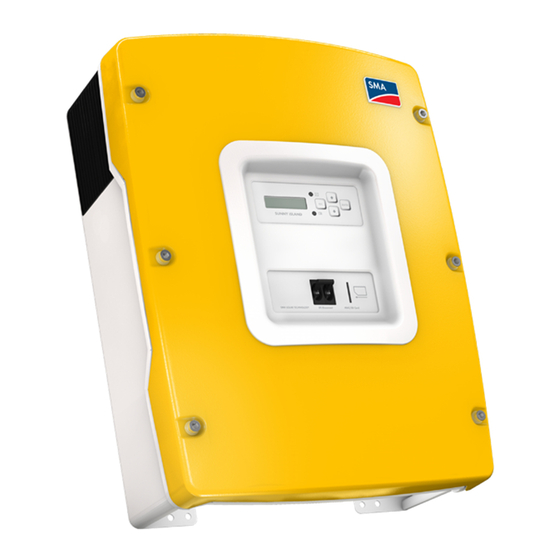
The Sunny Island 5048 SMA Solar Technology AG 2.2 At a glance The following figure provides an overview of all control elements and connections of the Sunny Island: SI5048-TB-TEN110340 Technical Description... - Page 19 SMA Solar Technology AG The Sunny Island 5048 Position Description Display LEDs showing device operation Control buttons Slot for the SD card Connection area for additional connections DC connection area AC connection area DC circuit breaker Technical Description SI5048-TB-TEN110340...
-
Page 20: Scope Of Delivery
The Sunny Island 5048 SMA Solar Technology AG 2.3 Scope of delivery Check that the delivery is complete. Check the packaging and the Sunny Island for externally visible damage. Contact your supplier in case of damage to the packaging. Please contact your dealer if you find any damage to the Sunny Island or if the delivery is incomplete. -
Page 21: Identifying The Sunny Island
SMA Solar Technology AG The Sunny Island 5048 Position Quantity Description 3-pole print terminal for connecting relays 1 and 2 M6x10 mm hexagon socket screw to attach the Sunny Island to the wall mounting bracket M6 contact washers to attach the Sunny Island to the wall... -
Page 22: Safety Instructions
Installation altitude The Sunny Island has been designed for use at elevations of up to 3000 m above sea level. Please contact SMA Solar Technology before using the device at elevations above 3000 m. A performance loss of 0.5 % per 100 m is to be expected starting at an elevation of... -
Page 23: Potential Hazards
SMA Solar Technology AG Safety Instructions 3.2 Potential Hazards DANGER! Electric shock upon contact due to high voltage and currents in the Sunny Island. Death or serious injuries. Complete protection against accidental contact by hand is only ensured when the following points are followed according to the manual: •... -
Page 24: Mounting
Mounting SMA Solar Technology AG 4 Mounting 4.1 Selecting the Mounting Location DANGER! Danger of death if installed in improper locations. Death or serious burns. Despite careful construction, electrical devices can cause fires. • Do not mount the Sunny Island on flammable construction materials. - Page 25 SMA Solar Technology AG Mounting • Do not mount in a horizontal position. • The connection area may not point upwards. • In a living area, do not mount the unit on plasterboard walls, etc. in order to avoid audible vibrations.
-
Page 26: Mounting The Sunny Island With The Wall Mounting Bracket
Mounting SMA Solar Technology AG 4.2 Mounting the Sunny Island with the Wall Mounting Bracket CAUTION! Risk of injury due to the Sunny Island falling during transport. Physical injury (fractures or crushing) and damage to the Sunny Island. • Take the Sunny Island's weight of 63 kg into account. - Page 27 SMA Solar Technology AG Mounting 2. Secure the wall mounting bracket to the wall using appropriate screws and washers. 3. Hang the Sunny Island onto the wall mounting bracket using the opening for this purpose in its back panel. 4. Screw the Sunny Island to the wall mounting bracket on both sides using the screws (M6x8) provided.
-
Page 28: Opening And Closing
Opening and Closing SMA Solar Technology AG 5 Opening and Closing The enclosure of the Sunny Island has a removable lid. Remove the enclosure lid only when installing the device or for required maintenance or repair work. 5.1 Opening the Sunny Island 1. -
Page 29: Closing The Sunny Island
SMA Solar Technology AG Opening and Closing 5.2 Closing the Sunny Island 1. Place the lid onto the enclosure and fasten it with the 6 screws and the corresponding washers. Tighten the screws with 6 Nm torque in the order shown in the figure on the right. The toothing of the washers must face toward the lid. -
Page 30: Electrical Connection
Electrical Connection SMA Solar Technology AG 6 Electrical Connection All cables are fed through the openings on the bottom side of the device (see next illustration) and connected to the appropriate connection terminals on the Sunny Island. Use the provided cable glands to fasten the cables inside the Sunny Island enclosure in a manner conforming to the appropriate standards. -
Page 31: Grounding
Calculating the Required Grounding Cable Cross-section SMA Solar Technology cannot provide generally valid values for the cross-section of the cable required for the external grounding of the battery. The cable dimensions depend on the type and size of the battery connected, the external fuse (DC side) and the material used in the grounding cable. -
Page 32: Dc Connection
Electrical Connection SMA Solar Technology AG 4. Install the cable gland with the adapter M20 (included in scope of delivery) in the cable third cable feed-through on the right. – Insert the cable gland with the thread in the cable opening. -
Page 33: Safety Precautions/Conditions
SMA Solar Technology AG Electrical Connection 6.2.1 Safety Precautions/Conditions Connect a suitable battery to the DC side (see section 22 ”Technical Data” (page 217)). DC must be connected observing all local valid guidelines and regulations. DANGER! Death hazard due to inappropriate handling of the battery. Death or serious chemical burns. -
Page 34: Cable Protection
Electrical Connection SMA Solar Technology AG 6.2.3 Cable Protection In addition to the internal DC circuit breaker, install a separate, external fuse as close as possible to the battery. Install a suitable fuse link for the fuse according to the maximum specified DC currents (e.g. - Page 35 SMA Solar Technology AG Electrical Connection Install the DC Terminals in the Following Sequence: 1. Loosen the cable gland on the Sunny Island. 2. Thread the DC cable through the cable gland. 3. Remove the protective insulation from the conductor and fit a suitable ring terminal lug to the exposed end of the conductor.
-
Page 36: Ac Connection
Electrical Connection SMA Solar Technology AG 6.3 AC Connection 6.3.1 Cable Protection Connect the Sunny Island to the stand-alone grid and to any other existing external source using a distribution sub-panel. Provide the distribution sub-panel with appropriate line circuit breakers, and observe all regional standards and guidelines. - Page 37 SMA Solar Technology AG Electrical Connection For connection, proceed as follows: Cable cross-section The maximum cable cross-section for connecting the loads / PV inverters is 16 mm 1. Sheathe the cable gland over the three-conductor cable and then insert the conductor through the cable opening into the Sunny Island.
-
Page 38: Ac2 (Generator/Grid)
Electrical Connection SMA Solar Technology AG 6.3.3 AC2 (Generator/Grid) The distribution sub-panel of the generator/power distribution grid is connected to the AC2 output of the Sunny Island. Single-phase parallel system In the case of single-phase parallel systems, also connect the generator or the grid to all slaves on AC2. -
Page 39: Additional Connections
SMA Solar Technology AG Electrical Connection 6.4 Additional Connections For installing the connections described below, feed the cables through the specified holes in the rubber connection block. Plugs for sealing the RJ45 communication cable for internal and external communication are provided in the cable insert upon delivery. Combining plugs allows you to establish 0 to 4 feed-throughs (2 plugs without a feed-through, 1 with 1 feed-through and 2 with 2 feed-throughs). - Page 40 Electrical Connection SMA Solar Technology AG For connection, proceed as follows: Polarity of the conductors The polarity of the two conductors is irrelevant for the functioning of the battery temperature sensor. 1. Pierce a hole in the rubber connection area at the corresponding position.
-
Page 41: Battery Current Sensor
SMA Solar Technology AG Electrical Connection 6.4.2 Battery Current Sensor In addition to the internal measurement, the Sunny Island provides the possibility to measure the battery current via a shunt. You need this function if you intend to operate additional DC generators and DC loads in your off-grid system. - Page 42 Electrical Connection SMA Solar Technology AG Connecting the Battery Current Sensor: Use cables of intrinsically safe circuits Always use cables of intrinsically safe circuits for the connection of battery current sensors. "Intrinsically safe" means here that the cable is double-insulated and that the wire melts but the insulation remains intact in the event of a short circuit.
-
Page 43: Communication For Multi-Device Connection
SMA Solar Technology AG Electrical Connection Commissioning the battery current sensor When connecting a battery current sensor to the Sunny Island, the device's internal offset must be adjusted during the first commissioning of the off-grid system. To do this, proceed as described in section 8.3 ”Commissioning the Battery Current Sensor”... - Page 44 Electrical Connection SMA Solar Technology AG Number of slaves Connection procedure 2 Slaves • Take the RJ45 cable coming from the master, insert it into the Sunny Island slave 1 and plug it into the "ComSyncIn" socket there. • Remove the terminating resistor in the Sunny Island slave 1 from the "ComSyncOut"...
-
Page 45: Multi-Function Relay 1 And 2
SMA Solar Technology AG Electrical Connection 6.4.4 Multi-function Relay 1 and 2 The Sunny Island offers you several options for the control of internal and external processes. For this purpose, two multi-function relays are integrated into the Sunny Island to which you can assign functions using the "241.01 Rly1Op"... - Page 46 Electrical Connection SMA Solar Technology AG For connection to the relay contact, proceed as follows: DANGER! Danger to life due to faulty insulation Death or serious injuries. • Securely disconnect the relay cable from the communication area and the AC area.
- Page 47 SMA Solar Technology AG Electrical Connection Power Contactor for Load Shedding The Sunny Island can automatically disconnect loads to protect the batteries from deep discharge. To do this, an external (AC or DC) power contactor must be installed between the Sunny Island and the loads (see also section 12.1 ”Load Shedding”...
-
Page 48: Batvtgout Power Supply
Electrical Connection SMA Solar Technology AG Generator start The Sunny Island can control generators. The Sunny Island directly supports generators that can be started and stopped using a single contact. Generators which require more than one contact must be connected to the Sunny Island via a Generator Manager (GenMan). This product can be acquired from SMA Solar Technology. -
Page 49: Digin Digital Input
SMA Solar Technology AG Electrical Connection 6.4.6 DigIn Digital Input These terminals are used as a digital input for external electrical sources. For example, the feedback contact for the "GenRn" for the generator manager (GenMan) is connected here. Related Functions If you connect a GenMan, or operate the system with the generator and grid (GenGrid) in parallel, use the relays on the master device in order to activate the respective functions. -
Page 50: Interface For External Communication
SMA Solar Technology AG 6.5 Interface for External Communication You can connect SMA Solar Technology communication devices (e.g., Sunny Boy Control, Sunny WebBox) or a PC with the appropriate software to a communication interface. A detailed cabling diagram can be found in the communication device manual, the software or on the Internet at www.SMA.de/en. - Page 51 SMA Solar Technology AG Electrical Connection For connection, proceed as follows: NOTICE! Electrostatic discharges can damage the communication interface. Internal components of the Sunny Island can be irreparably damaged by static discharge. • Ground yourself before touching a component. 1. Remove the right plug of the two plugs in the rubber connection area.
- Page 52 Electrical Connection SMA Solar Technology AG Connecting Sunny Island to the Sunny Boy/Sunny Mini Central/Sunny Tripower/ Windy Boy and Sunny WebBox with one RS485 cable Connecting Sunny Island to the Sunny Boy/Sunny Mini Central/Sunny Tripower/ Windy Boy and Sunny WebBox with separate RS485 cables...
-
Page 53: Control Elements
SMA Solar Technology AG Control Elements 7 Control Elements In order to commission the Sunny Island, you should familiarize yourself with its operation beforehand. The individual control elements can be seen in the following figure. Position Description Display LEDs Control buttons... -
Page 54: Display Messages
Control Elements SMA Solar Technology AG 7.1 Display Messages The display of the Sunny Island has two lines, each with 16 characters. For details, see section 10.6 ”Display Messages (Overview)” (page 77). Position Description Output power / charging power (load status) Direction of energy flow and system status... -
Page 55: Buttons
SMA Solar Technology AG Control Elements 7.3 Buttons The table explains the functions of the buttons on the Sunny Island: Button Function cancels the selected function answers NO navigates one menu level higher stops device (when held pressed down) navigates up one list element, increases data value... -
Page 56: Initial Start-Up
Always save data Always use the SD card to save data and events. This way, in case of a failure, SMA Solar Technology can help you quickly. -
Page 57: Starting The Quick Configuration Guide (Qcg)
SMA Solar Technology AG Initial Start-up 8.2 Starting the Quick Configuration Guide (QCG) Error occurrence If the device displays an error message unexpectedly, this error must be fixed before the Sunny Island can be put into operation. For this purpose, refer to section 20 ”Troubleshooting”... - Page 58 Initial Start-up SMA Solar Technology AG – "New Battery" (if you wish to reset battery-specific parameters only. You cannot change general parameters using "New Battery". – "Emerg Charge" (if you would like to charge a deeply discharged battery using an external source) 3.
- Page 59 SMA Solar Technology AG Initial Start-up Displayed text Description PvOnly Off Grid, no grid, no generator Stand-alone grid with generator Grid Power distribution grid GenGrid Power distribution grid and generator GenGrid: – Maximum generator current (0 A - 224 A), default setting: "16 A"...
-
Page 60: Commissioning The Battery Current Sensor
Initial Start-up SMA Solar Technology AG 8.3 Commissioning the Battery Current Sensor In the event you have installed a battery current sensor in your system, you are required to synchronize the device's internal offset. To do this, proceed as follows: 1. Switch the Sunny Island to standby as described in section 9.2 ”Stopping the Sunny Island (Standby)”... - Page 61 SMA Solar Technology AG Initial Start-up 7. Reconnect the battery current sensor's lines correctly as displayed in the graphic. Make sure the lines have the correct polarity when doing this. – BatCur+ to terminal 1 – BatCur– to terminal 2 8.
-
Page 62: Switching On And Off
Switching On and Off SMA Solar Technology AG 9 Switching On and Off 9.1 Switching On Systems with several Sunny Islands Switch on the Slaves before you switch on the master. To do this, proceed as follows. 1. Check the following requirements: –... -
Page 63: Stopping The Sunny Island (Standby)
SMA Solar Technology AG Switching On and Off 4. Wait 5 seconds. ☑ The Sunny Island skips the QCG and the notification shown here is displayed. 5. Press and hold <ENTER>. ☑ The remaining time is displayed as a bar. -
Page 64: Switching Off
Switching On and Off SMA Solar Technology AG 9.3 Switching Off To switch off the Sunny Island, proceed as follows: "Switching sequence" Only with the sequence shown here can you ensure that all internal meter positions/values are saved. 1. Stop the Sunny Island as described in section 9.2 ”Stopping the Sunny Island (Standby)”... - Page 65 SMA Solar Technology AG Switching On and Off 1. Switch the Sunny Island DC circuit breaker to the "OFF" position. DANGER! Danger to life due to high voltages in the Sunny Island. After an automatic disconnection, high residual voltages can remain in the Sunny Island capacitors.
-
Page 66: Operation
Operation SMA Solar Technology AG 10 Operation The main menu consists of a "Home Screen" and the other main menu entries, which split up into the different menu levels. Operating states, for example, the current operating mode, power, etc. are displayed on the "Home Screen" (see section 10.6 ”Display Messages (Overview)” (page 77)). -
Page 67: Menu Structure
SMA Solar Technology AG Operation Single Point of Operation Single Point of Operation also means that all master log data, including the slave log data, is saved at the master device on the SD card. Messages Messages can be displayed at any time while the device is in operation and they have priority over the "Home Screen"... - Page 68 Operation SMA Solar Technology AG Overview of the Menu Structure: SI5048-TB-TEN110340 Technical Description...
- Page 69 SMA Solar Technology AG Operation 100# Meters - Display values In this main menu, you will find the display values for the following components of the stand-alone grid system: • 110# Meter Inverter - Sunny Island • 120# Battery Meters - Battery •...
-
Page 70: Changing Parameters
Operation SMA Solar Technology AG 600# Direct Access -Direct access to the parameters This is a main menu that gives you direct access to the settings and display values (see section 10.3 ”Direct Access - Direct Access to the Parameters” (page 71)). -
Page 71: Direct Access - Direct Access To The Parameters
SMA Solar Technology AG Operation The Sunny Island displays a corresponding message for parameters that can only be changed in standby mode or require a different password level. Display Description Incorrect password level, you cannot make any changes in the menus. This is explained in section 10.5 ”Entering the Installer Password”... -
Page 72: Compact Meters
Operation SMA Solar Technology AG 10.4 Compact Meters The "150# Compact Meters" menu is intended primarily to help the installer commission the device. The display gives you information at a glance on the following areas: • Battery 1 • Battery 2 •... - Page 73 SMA Solar Technology AG Operation Bat 2 (Battery Value 2) Position Description Name of the compact meter Battery voltage (BatVtg) Setpoint of charging voltage (BatChrgVtg) Active charging process (BatChrgOp) Remaining absorption time (AptTmRmg) Inv (AC Values of Inverter) Position Description...
- Page 74 Operation SMA Solar Technology AG InvTot (Total AC Values of Inverter) Position Description Name of the compact meter Total active power of the inverter (cluster) Total reactive power of the inverter (cluster) Ext (AC Values of External Source) Position Description...
- Page 75 SMA Solar Technology AG Operation ExtTot (Total AC Values of External Source) Position Description Name of the compact meter Total active power of the external source (cluster) Total reactive power of the external source (cluster) OpStt (Inverter and Generator Status)
-
Page 76: Entering The Installer Password
Do not provide the following information for entering the installer password to unauthorized persons. Illegal provision of this information to other persons will lead to invalidation of all guarantees by the SMA Solar Technology. Entering the password The Sunny Island allows you to enter the password not only in standby, but also during operation. -
Page 77: Display Messages (Overview)
SMA Solar Technology AG Operation ☑ The installer password has been entered. Operating level [1] = the installer level is set. 9. Exit the menu by pressing the <ESC> key. Switching operating levels If the password is invalid, the Sunny Island does not switch to the installer level. In this case, recalculate and re-enter the installer password as described in this section. - Page 78 Operation SMA Solar Technology AG "Home Screen" Position Description Output power / charging power (load status) Direction of energy flow and system status Grid status Device assignment Status of the external source (asterisk, question mark or exclamation mark) Relay 1 status...
- Page 79 SMA Solar Technology AG Operation Messages on the slave devices The slave devices only show the bar display for output and charging power and the device assignment in the bottom line (e. g. S1 for slave 1) as well as the status of external sources, if applicable (*, for the description see above).
- Page 80 Operation SMA Solar Technology AG Symbol Meaning "Cycle" request reason: The generator was requested via the generator operation's time-dependent repetition cycle (Parameter: 235.17 GnTmOpCyc). This symbol can only be shown in Multicluster operation. "External" request reason: The generator was requested via the extension cluster. This only applies to Multicluster operation.
-
Page 81: Parameter Display
SMA Solar Technology AG Operation 10.7 Parameter Display Parameters on the Sunny Island are displayed as follows: In the upper line, the parameter number comes first, then a separator (hash) followed by the parameter name. In the lower line, there is the value with the unit and the modification mark (enter arrow) is on the far right. -
Page 82: Display Of Warnings And Failures
Operation SMA Solar Technology AG 10.9 Display of Warnings and Failures The Sunny Island can display a list of errors and warnings: The serial number (quantity) of the error is on the upper line; the time and date display changes in 2-second intervals. -
Page 83: Archiving Data On A Sd Card
3 figures after the dot. Type of Memory Card SMA Solar Technology recommends using SD cards manufactured by Transcend. If you use a memory card from another manufacturer, check whether the card is FAT-16 formatted. If necessary, format the card. Be aware that data stored on the card will be lost. - Page 84 Statistical values of the battery. These values are saved every day at 10:00 p.m. batstat.sma Internal data from SMA Solar Technology si.ccf System information from Sunny Island. "BOOTEX.LOG" File The file "BOOTEX.LOG" is not necessarily saved on the card, it is generated according to the operating system used (e.
- Page 85 Always save data Always use the SD card to save data and events. This way, in case of a failure, SMA Solar Technology can help you quickly. The data saved on the SD card can be processed using common table calculation programs.
-
Page 86: Inserting The Card
Archiving Data on a SD Card SMA Solar Technology AG 11.1 Inserting the Card NOTICE! Damage due to electrostatic discharges. • Ground yourself before you insert or remove the SD card from the Sunny Island enclosure. Insert the SD card with the cut corner pointing down into the slot on the Sunny Island (see illustration). -
Page 87: Removing The Sc Card
SMA Solar Technology AG Archiving Data on a SD Card 11.2 Removing the SC Card To ensure that all log data is saved upon deactivation, write all data not yet saved from the buffer to the SD card by using the parameter "550.03 CardFunc" with the option "ForcedWrite". -
Page 88: Status Messages
Archiving Data on a SD Card SMA Solar Technology AG 11.5 Status Messages Using the "312.07 CardStt" parameter, you can request the status of your SD card: Display Description The SD card is deactivated. The SD card is activated. The memory capacity of your SD card has been exceeded. -
Page 89: Updating The Firmware
1. Create a backup copy of the existing parameter lists (see section 11.3 ”Saving and Loading Parameters” (page 87)). 2. Download the current version of the firmware from the Internet at www.SMA.de/en. 3. Copy the "UPDATE.BIN" file onto the SD card. 4. Set the master device to standby. - Page 90 Archiving Data on a SD Card SMA Solar Technology AG Starting QCG If you have carried out a firmware update in which the number before the dot in the firmware version has changed, it is advisable to start QCG and to perform all settings anew.
- Page 91 SMA Solar Technology AG Archiving Data on a SD Card Sunny Island Display message Explanation Master Master update part 2/2. ⋮ Slave The slave update starts. ⋮ Master The slave update is running. ⋮ Master The master update is completed.
-
Page 92: Additional Functions
Additional Functions SMA Solar Technology AG 12 Additional Functions 12.1 Load Shedding If, over an extended period, the loads connected to the Sunny Island use more energy than that which the generators connected produce, the battery can deeply discharge. The Sunny Island shuts down automatically if the state of charge of the battery is too low. - Page 93 SMA Solar Technology AG Additional Functions Soc [%] Lod1SocTm1 Stp Lod1SocTm2 Stp Lod1SocTm2 Stp Lod1SocTm1 Str Lod1SocTm2 Str Lod1SocTm2 Str Lod1Tm1Str Lod1Tm2Str The figure shows an example of the settings if the load shedding function at night is to be avoided as much as possible.
-
Page 94: Sleep Mode
Additional Functions SMA Solar Technology AG 12.2 Sleep Mode Using the "250.10 SleepEna" parameter set to "Enable" allows the sleep mode to be activated in single-phase grids, which the master uses to switch off the slaves when the power value allows this. -
Page 95: Overload And Short-Circuit Behavior
SMA Solar Technology AG Additional Functions 12.4 Overload and Short-Circuit Behavior The Sunny Island can be temporarily operated under overload conditions. It can also supply short- circuit currents. In case of overload, the Sunny Island supplies an output of 6 500 W for 30 minutes and can supply 7 200 W for 5 minutes. -
Page 96: Time-Controlled Standby
Additional Functions SMA Solar Technology AG 12.7 Time-Controlled Standby You can set the Sunny Island to standby mode in a time-controlled way. Activate the time-controlled standby using the parameter "250.13 SlpAtNgt". Set the parameter to "Enable". After activation, set the start time and the stop time for standby. Carry out the setting using the "250.14 SlpStrTm"... -
Page 97: Battery Management
SMA Solar Technology AG Battery Management 13 Battery Management The battery management of the Sunny Island supports the following three battery types ("221.01 BatTyp" parameter): • FLA • VRLA • NiCd The battery capacity ("221.02 BatCpyNom" parameter) is to be entered as the nominal capacity for a ten hour discharge (C10). -
Page 98: Start Options
Battery Management SMA Solar Technology AG NOTICE! Possible damage to the battery as a result of faulty temperature measurement If the battery temperature sensor is defective or missing, the Sunny Island continues to run, assuming the battery has a temperature of 40 °C. This can result in insufficient charging of the battery in the long run. -
Page 99: Charge Control
SMA Solar Technology AG Battery Management The battery's state of health (display value "320.01 Soh") is a measurement of the present useable capacity expressed as a percentage relative to the nominal capacity. 100 % means that the entire nominal capacity can be used. 50 % means that only half of the original nominal battery capacity can be used. - Page 100 Battery Management SMA Solar Technology AG In this phase, the battery voltage is maintained at a constant level, resulting in a continually decreasing battery current. The Sunny Island remains in this phase for a defined period of time ("222.02 — 222.03", AptTmBoost or AptTmFul or AptTmEqu" parameters). For this charging phase, the Sunny Island automatically selects one of three possible charging methods (boost, full, equalizing) which are described in detail in sections 13.4.1 ”Boost Charge”...
-
Page 101: Boost Charge
SMA Solar Technology AG Battery Management The charging capability of batteries is highly dependent on the battery temperature. For temperatures < 20 °C, the charging voltage must be slightly increased, and for temperatures > 20 °C, it must be slightly decreased. This is necessary to prevent overcharging and insufficient charging reliably at any battery temperature. -
Page 102: Equalization Charge
Battery Management SMA Solar Technology AG Parallel procedures for full charge Any parallel procedures causing the generator to stop during the full charging process are not taken into account until the charging process is completed. 13.4.3 Equalization Charge A battery bank consists of many individual battery cells connected in series which all behave slightly different. -
Page 103: Manual Equalization Charge
SMA Solar Technology AG Battery Management 13.4.4 Manual Equalization Charge The parameter "520.01 ChrgSelMan" activates the manual equalization charge on the Sunny Island. If a generator is connected to the system, it is automatically started and stopped once the equalization charge is completed. -
Page 104: Battery Preservation Mode
Battery Management SMA Solar Technology AG 13.5 Battery Preservation Mode The Sunny Island has a sophisticated battery preservation mode. The battery preservation mode prevents deep discharge from the battery as far as possible when the energy supply is low, thus preventing a total system failure as well as damage to the battery. -
Page 105: Battery Diagnostics
SMA Solar Technology AG Battery Management The limits for all three levels can be set independently from each other. This allows individual levels to be skipped. Parameter BatPro1Soc < BatPro2Soc If the BatPro1Soc parameter < BatPro2Soc, level 1 is skipped and only level 2 is carried out. -
Page 106: Battery Lead Resistance
Battery Management SMA Solar Technology AG 13.7 Battery Lead Resistance In menu "221# Battery Property", you can specify the battery lead resistance (BatWirRes). The resistance is the ohmic resistance from the battery to the input of the Sunny Island master device. -
Page 107: Connecting External Sources
SMA Solar Technology AG Connecting External Sources 14 Connecting External Sources The Sunny Island supports the integration of external energy sources. Here, a distinction is made between the integration of a generator and the integration of the power distribution grid. Both the generator as well as the power distribution grid are integrated through the AC2 connection of the Sunny Island. -
Page 108: Connecting In Parallel
Connecting External Sources SMA Solar Technology AG 14.1.1 Connecting in Parallel In the case of Sunny Islands connected in parallel which operate on the same phase and in the same cluster, the internal transfer relay is activated simultaneously. It is thus possible to multiply the generator current and therefore to connect a larger generator or a higher grid current. - Page 109 SMA Solar Technology AG Connecting External Sources Manual (Manual Generator Start) This setting is for generators that do not have an electrical remote starting option and, for example, are started using cable winches or cranks, or similarly. In this case, the Sunny Island does not have the option of starting the generator. It only monitors the generator input (AC2).
- Page 110 Connecting External Sources SMA Solar Technology AG Autostart This allows autostart generators to be directly integrated. They have a separate internal controller that controls the start procedure. The Sunny Island requests the generator via the GnReq signal. If the generator voltage and frequency are within the set limits (see section 14.1.6 ”Limits and Power Adjustment”...
- Page 111 SMA Solar Technology AG Connecting External Sources Generator request If the generator is running after being externally started and a generator request occurs, the GnReq signal is disabled until the generator is externally stopped again and the stop time has expired.
-
Page 112: Generator Operation
Connecting External Sources SMA Solar Technology AG The generator is disconnected by the Sunny Island after the GENRDY signal has been withdrawn by the GenMan. NOTICE! Occurrence of unpredictable operating states. • Never carry out a manual start directly at the generator. - Page 113 SMA Solar Technology AG Connecting External Sources Generator Interface "234.07 GnStrMod" = Manual; Start at the Generator Manual generator start "Generator is running" detected, beginning of warm up phase Internal generator request is ignored Warm-up phase is completed, generator is connected...
-
Page 114: Automatic Generator Operation
Connecting External Sources SMA Solar Technology AG 14.1.5 Automatic Generator Operation In automatic operating mode ("235.01 GnAutoEna" parameter), the Sunny Island automatically defines the settings (depending on battery state of charge or load) as to when the generator starts and how long it runs. The automatic operating mode is activated using GnAutoEna = On (default). - Page 115 SMA Solar Technology AG Connecting External Sources Reaching the float charging process If the float charging process (see section 13.4 ”Charge Control” (page 99)) is activated before the cutoff limit (GnSocTm1Stp or GnSocTm2Stp) is reached, the generator request is disabled again. If a full or equalization charge is active, the generator is only stopped after this charge is completed and not when "235.04 GnSocTm1Stp"...
- Page 116 Connecting External Sources SMA Solar Technology AG Load-Dependent Start In case increased energy demands arise, the generator can be requested for support. This function can be switched on or off (default) using the "235.09 GnPwrEna" parameter. The function is only effective if the "235.01 GnAutoEna"...
- Page 117 SMA Solar Technology AG Connecting External Sources Generator Interface "234.07 GnStrMod" = Autostart; Generator Request Via Sunny Island Generator started by Sunny Island Generator start Beginning of warm up time Warm-up time has expired Generator is connected Current limit Minimum running time is expired...
-
Page 118: Limits And Power Adjustment
Connecting External Sources SMA Solar Technology AG 14.1.6 Limits and Power Adjustment The voltage limits can be set using the "234.01 GnVtgMin" and "234.02 GnVtgMax" parameters and the frequency limits for generator operation can be set using the "234.05 GnFrqMin" and "234.06 GnFrqMax"... -
Page 119: Run Times
SMA Solar Technology AG Connecting External Sources 14.1.7 Run Times If the generator is started (or the Sunny Island detects an external generator start), the warm up phase starts. If, during this time, the voltage or frequency detected is not within the permissible range, the warm-up time begins again. -
Page 120: Operation Together With Pv Inverters
Connecting External Sources SMA Solar Technology AG The "133.03 GnRmgTm" display value is used to display the remaining time of the generator meter. Depending on the current request or the phase in which the generator state machine is, the following times are displayed: •... -
Page 121: Stopping The Generator
SMA Solar Technology AG Connecting External Sources 14.1.9 Stopping the Generator If the generator was started via the Sunny Island (automatically or manually), it can be manually stopped at any time using the "540.01 GnManStr" parameter. This disconnects the generator (the minimum run time is not taken into account here) and the after-run time (Cool) is skipped. -
Page 122: Grid
Connecting External Sources SMA Solar Technology AG Slave Device Failure You can influence the behavior of the cluster upon failure of a slave device. For more information, see section 12.8 ”Reaction in Case of Failures” (page 96). 14.2 Grid The Sunny Island supports the operation of grid backup systems on the grid. Here, a distinction is made between two main states: either a power distribution grid and stand-alone grid system are connected or a power distribution grid and stand-alone grid system are disconnected. -
Page 123: Voltage And Frequency Limits
SMA Solar Technology AG Connecting External Sources 14.2.1 Voltage and Frequency Limits In order to operate on the grid, very strict limits (for voltage and frequency) must generally be maintained. These strict limits are not sensible for generator operation. The limits are therefore set separately for grid operation and the generator limits are not used. -
Page 124: Grid Reconnection
Connecting External Sources SMA Solar Technology AG 14.2.4 Grid Reconnection In stand-alone grid operation, the Sunny Island constantly checks whether the grid has been reconnected (see above). The following conditions have to be fulfilled to guarantee that the Sunny Island synchronizes with the supply grid and connects to the supply grid: •... -
Page 125: Grid Failure
SMA Solar Technology AG Connecting External Sources Feeding Operation Whether energy is fed from the stand-alone grid system into the power distribution grid is controlled using the "232.08 GdMod" parameter. In all cases, make sure to consult your network operator if grid feed-in is possible. -
Page 126: Disturbances
Connecting External Sources SMA Solar Technology AG 14.2.7 Disturbances Reverse Power If the defined reverse power ("232.09 GdRvPwr" parameter) is exceeded for the time "232.10 GdRvTm", the grid is disconnected. After reverse power, connection is blocked for at least "231.03 ExtLkTm". -
Page 127: Operation Together With Pv Inverters
SMA Solar Technology AG Connecting External Sources 14.2.9 Operation Together with PV Inverters Since electricity is fed into the grid through the relay of the Sunny Island, it must be prevented from overloading. For this reason, reverse power monitoring is used that, if required, disconnects the connection to the power distribution grid if the reverse power limit is exceeded. -
Page 128: Generator And Grid
• If a manual switch is installed, leave the switch in OFF-position for at least 5 seconds before switching to the new position. • Upon request to the SMA Serviceline, you can obtain the manual on how to install a switch for connecting the Sunny Island to the power distribution grid and to a generator. - Page 129 SMA Solar Technology AG Connecting External Sources 3. Connect the positive pole of the BatVtgOut connection to the second contact of the same auxiliary contact on the transfer switch. An auxiliary contact is used because the Sunny Island must "know" whether it is connected to the power distribution grid or whether it must manage a diesel generator.
-
Page 130: Relays
Relays SMA Solar Technology AG 15 Relays The Sunny Island offers you several options for the control of internal and external processes. For this purpose, two relays are integrated into the device, to which you can assign functions using the parameters "241.01 Rly1Op" and "241.02 Rly2Op". - Page 131 SMA Solar Technology AG Relays Function/Setting Meaning Function description GdOn Power distribution grid Relay switching when power distribution grid is available and connected. Error Error Sunny Island has a fault; in case of fault, contact is open (relay is deactivated).
-
Page 132: Multicluster Operation
Multicluster Operation SMA Solar Technology AG 16 Multicluster Operation 16.1 Communication between the Sunny Island For increased output, up to 12 Sunny Island clusters can be interconnected to form a Multicluster system. Within each cluster, a communication cable connects the master to the slaves. Each cluster is connected to the others via another communication cable, connected to the respective master. - Page 133 SMA Solar Technology AG Multicluster Operation Electrostatic discharge Electrostatic discharges are an acute danger to the Sunny Island and to the communication interface. Ground yourself before removing the communication interface from the packaging, and before touching any components within the Sunny Island. To achieve this, touch PE.
- Page 134 Multicluster Operation SMA Solar Technology AG Proceed as follows when connecting the communication cable: 1. Remove the left of the two plugs in the rubber connection area. 2. Feed the RJ45 cable from the outside through the plugs inside the Sunny Island master.
-
Page 135: Initial Start-Up Of The Multicluster System
SMA Solar Technology AG Multicluster Operation 16.2 Initial Start-up of the Multicluster System 1. Carry out steps 1 - 3 in section 8.2 ”Starting the Quick Configuration Guide (QCG)” (page 57). 2. At "New System" set the following parameters: – Device type (master, slave 1, slave 2, slave 3) –... -
Page 136: Switching A Multicluster System On And Off
Multicluster Operation SMA Solar Technology AG 16.3 Switching a Multicluster System On and Off 16.3.1 Activation / Startup Switching on a Multicluster system can only take place at the master of the main cluster. The extension clusters will be started automatically after starting the main cluster. To do this, the DC circuit breakers of all Sunny Islands in the extension cluster must be set to "ON". -
Page 137: Generator Operation
SMA Solar Technology AG Multicluster Operation 16.4 Generator Operation The main master's generator request comprises its own request (based on SOC, time, etc.) and possible requests from one or more extension clusters. The generator remains in a requested state as long as a request is present. -
Page 138: Communication Test
Multicluster Operation SMA Solar Technology AG 16.6 Communication Test Using the parameter "510.08 TstClstCom" a communication test between the clusters can be started from each master device of a cluster. Switch only one master device of the extension cluster to "Transmit". -
Page 139: Error Handling In A Multicluster System
SMA Solar Technology AG Multicluster Operation 16.9 Error Handling in a Multicluster System For Multicluster system operation, the entire main cluster is always required. If a device in the main cluster fails (master and/or slave), this causes the main cluster to stop. -
Page 140: Pv Inverters In Stand-Alone Grid Systems
To change grid-relevant parameters on the PV inverter (Sunny Boy, Sunny Mini Central or Sunny Tripower) you need a personal access authorization, the SMA Grid Guard password. Call the SMA Serviceline to obtain your personal SMA Grid Guard password. DANGER! Feedback may occur if the power distribution grid fails. -
Page 141: Setting Via Rotary Switch With Sb 3000Tl/4000Tl/5000Tl
SMA Solar Technology AG PV Inverters in Stand-alone Grid Systems 17.1.1 Setting via Rotary Switch with SB 3000TL/4000TL/5000TL. 1. Set the rotary switch, A, with a screwdriver (2.5 mm) to position "E". 2. Set the chosen language via the rotary switch B with a screwdriver (2.5 mm). You can find the configuration of the switch in the manual of the PV inverter. - Page 142 PV Inverters in Stand-alone Grid Systems SMA Solar Technology AG After you have set the PV inverter to stand-alone operation, the following PV inverter parameters automatically change: No. Parameters Unit Value I-NiTest Off (MSD = 0) Vac-Min Vac-Max Fac-delta– − 4.5 (starting from base...
-
Page 143: Use Of Sb 3000Tl/4000Tl/5000Tl In 60 Hz Grids
(solar) power available from the PV array exceeds the power required by the connected loads. To prevent the excess energy from overcharging the battery, the Sunny Island 5048 recognizes this situation and changes the frequency at the AC output. This frequency adjustment is analyzed by the PV inverter. - Page 144 PV Inverters in Stand-alone Grid Systems SMA Solar Technology AG This function is shown in the following figure: The different settings have the following meanings: • f = 0 refers to the base frequency of the micro grid created by the Sunny Island.
-
Page 145: Maintenance And Care
Dispose of the Sunny Island at the end of its service life in accordance with the disposal regulations for electronic waste which apply at the installation site at that time. Alternatively, send the devices back to SMA Solar Technology with shipping paid by sender, and labeled "ZUR ENTSORGUNG" ("FOR DISPOSAL") (section 23 ”Contact” (page 220)). -
Page 146: Parameter Lists
Parameter lists SMA Solar Technology AG 19 Parameter lists 19.1 Display Values All parameters contained in this section are display values. These parameters can only be read. The parameters with a gray background are only visible after the installer password has been entered. - Page 147 SMA Solar Technology AG Parameter lists 113# Inverter Slave1 Meters Number Name Description Value Explanation InvOpSttSlv1 Operating state of the Standby Standby Sunny Island slave 1 Operation EmCharge Emergency charge mode Error Error Startup Transfer standby > operation InvPwrAtSlv1 Active power Sunny Island...
- Page 148 Parameter lists SMA Solar Technology AG 114# Inverter Slave2 Meters Number Name Description Value Explanation InvOpSttSlv2 Operating state of the Standby Standby Sunny Island slave 2 Operation EmCharge Emergency charge mode Error Error Startup Transfer standby > operation InvPwrAtSlv2 Active power of the Sunny Island...
- Page 149 SMA Solar Technology AG Parameter lists 115# Inverter Slave3 Meters Number Name Description Value Explanation InvOpSttSlv3 Operating state of the Standby Standby Sunny Island slave 3 Operation EmCharge Emergency charge mode Error Error Startup Transfer standby > operation InvPwrAtSlv3 Active power of the Sunny Island...
-
Page 150: Battery Meters (120#)
Parameter lists SMA Solar Technology AG 19.1.2 Battery Meters (120#) Number Name Description Value Explanation (Plain text no.) BatSoc Momentary state of charge of battery (SOC) in % BatVtg Battery voltage in V BatChrgVtg Charging voltage target value in V AptTmRmg... -
Page 151: External Meters (130#)
SMA Solar Technology AG Parameter lists 19.1.3 External Meters (130#) 131# Total Meters Number Name Description TotExtPwrAt Total active power of the external source in kW TotExtCur Total current of the external source in A TotExtPwrRt Total reactive power in kVAr... - Page 152 Parameter lists SMA Solar Technology AG 133# Generator State Number Name Description Value Explanation (Plain text no.) GnDmdSrc Source for generator request: None (1) No request Bat (2) State-dependent battery charging Lod (3) Load-dependent Tim (4) Time-controlled Run1h (5) Requested for 1 hour...
- Page 153 SMA Solar Technology AG Parameter lists 134# Device Meters Number Name Description ExtPwrAt Active power of the external source in kW ExtVtg Voltage of the external source in V ExtCur Current of the external source in A ExtFrq Frequency of the external source in Hz...
-
Page 154: Charge Controller (140#)
Parameter lists SMA Solar Technology AG 138# Chp Meters Number Name Description Value Explanation ChpStt State of CHP plant Idle Operation Lock Locked after operation ChpPwrAt Power of the CHP plant ChpRmgTm Remaining time of the CHP (minimum run time) in hours, minutes and seconds... - Page 155 SMA Solar Technology AG Parameter lists 143# SIC40 2 Number Name Description Sic2EgyCntIn Energy of the second Sunny Island Charger in kWh Sic2TdyEgyCntIn Daily yield of the second Sunny Island Charger in kWh Sic2PvPwr PV power of the second Sunny Island Charger in W...
-
Page 156: Battery Settings (220#)
Parameter lists SMA Solar Technology AG 19.1.5 Battery Settings (220#) 221# Battery Property Number Name Description Value Explanation BatTyp Battery type VRLA Closed lead acid batteries with immobilized electrolyte in gel or AGM (Absorbent Glass Mat Separator). A sealed lead acid battery with liquid electrolyte. -
Page 157: System Settings (250#)
SMA Solar Technology AG Parameter lists 19.1.6 System Settings (250#) Number Name Description Value Explanation ClstCfg Cluster configuration Slave1 Cluster slave 1 Slave2 Cluster slave 2 Slave3 Cluster slave 3 1Phase1 Single-phase, 1 Sunny Island inverter 1Phase2 Single-phase, 2 Sunny Island inverters... -
Page 158: Adjustable Parameters
Parameter lists SMA Solar Technology AG 19.2 Adjustable Parameters All parameters contained in this section are adjustable. You can only adjust the parameters with a gray background after the installer password has been entered. Some of the parameters with a gray background are only visible after the installer password has been entered. - Page 159 SMA Solar Technology AG Parameter lists 222# Battery Charge Mode Number Name Description Value Explanation Default Value BatChrgCurMax Charging current of the 10 A ... 1,200 A battery 1200 A AptTmBoost Absorption time for 1 min... VRLA 120 min normal charge...
- Page 160 Parameter lists SMA Solar Technology AG Number Name Description Value Explanation Default Value BatTmpCps Battery temperature 0 mV / °C VRLA 4.0 mV/°C compensation 10 mV / °C 4.0 mV/°C NiCd 0 mV/°C AutoEquChrgEna Automatic equalization Disable Disable Enable charge...
- Page 161 SMA Solar Technology AG Parameter lists 225# Battery Current Sensor Number Name Description Value Explanation Default Value BatCurSnsTyp Type of battery current None No sensor is None sensor connected. 60 mV Battery Current Sensor 60 mV 50 mV Battery Current...
-
Page 162: External Settings (230#)
Parameter lists SMA Solar Technology AG 19.2.3 External Settings (230#) 231# Ext General Number Name Description Value Explanation Default Value PvFeedTmStr Start time for PV grid 04:00:00 feeding-in PvFeedTmStp Stop time for PV grid 22:00:00 feeding-in ExtLkTm Lock time after reverse... - Page 163 SMA Solar Technology AG Parameter lists Number Name Description Value Explanation Default Value GdMod Grid interface GridCharge Charging on GridCharge the grid GridFeed Charging and feedback on the grid GdRvPwr Permissible grid 0 W ... 100 W reverse power 5000 W...
- Page 164 Parameter lists SMA Solar Technology AG 233# Grid Start Number Name Description Value Explanation Default Value GdSocTm1Str SOC limit for switching on 40 % the grid for time 1 GdSocTm1Stp SOC limit for switching off 80 % the grid for time 1...
- Page 165 SMA Solar Technology AG Parameter lists 234# Generator Control Number Name Description Value Explanation Default Value GnVtgMin Minimum generator 172.5 V voltage GnVtgMax Maximum generator 250 V voltage GnCurNom Nominal generator 16.0 A current GnFrqNom Generator nominal 230 V / 50 Hz 50.00 Hz...
- Page 166 Parameter lists SMA Solar Technology AG Number Name Description Value Explanation Default Value GdAlSns AI sensitivity Normal Medium Medium Normal Normal High High 235# Generator Start Number Name Description Value Explanation Default Value GnAutoEna Generator autostart Disable Enable GnAutoStr Number of autostarts...
- Page 167 SMA Solar Technology AG Parameter lists Number Name Description Value Explanation Default Value GnTmOpEna Time-controlled Disable Disable Disable generator operation Enable Enable GnTmOpStrDt Starting date for time- 2010-01-01 controlled generator operation GnTmOpStrTm Starting time for time- controlled generator operation in hours,...
- Page 168 Parameter lists SMA Solar Technology AG 236# CHP Control Number Name Description Value Explanation Default Value ChpOpTmMin Minimum run time of 60 min CHP plant ChpStpTmMin Minimum stop time of 10 min CHP plant ChpPwrMax Maximum power of 5 kW...
- Page 169 SMA Solar Technology AG Parameter lists Number Name Description Value Explanation Default Value ChpPwrEna Activate CHP plant Disable Disable Enable request based on Enable Enable power ChpPwrStr Combined heat and 4 kW power system request switch-on power limit ChpPwrStrDly Time delay for power...
-
Page 170: Relay Settings (240#)
Parameter lists SMA Solar Technology AG 19.2.4 Relay Settings (240#) 241# Relay General Number Name Description Value Explanation Default Value Rly1Op Function of relay 1 Off AutoGn AutoGn Generator request AutoLodExt External loadshedding AutoLod1Soc SOC1 Loadshedding AutoLod2Soc SOC2 Loadshedding Tmr1 Timer 1... - Page 171 SMA Solar Technology AG Parameter lists Number Name Description Value Explanation Default Value Rly2Op Function of relay 2 Off AutoLodExt AutoGn Generator request AutoLodExt External loadshedding AutoLod1Soc SOC1 Loadshedding AutoLod2Soc SOC2 Loadshedding Tmr1 Timer 1 Tmr2 Timer 2 AptPhs Absorption phase...
- Page 172 Parameter lists SMA Solar Technology AG 242# Relay Load Number Name Description Value Explanation Default Value Lod1SocTm1Str SOC limit for load 30 % shedding 1 start for t1 Lod1SocTm1Stp SOC limit for load 50 % shedding 1 stop for t1...
- Page 173 SMA Solar Technology AG Parameter lists 243# Relay Timer Number Name Description Value Explanation Default Value RlyTmr1StrDt Start date for timer 1 2010-01-01 RlyTmr1StrTm Start time for relay control timer 1 in hours, minutes and seconds RlyTmr1Dur Running time for relay...
- Page 174 Parameter lists SMA Solar Technology AG 244# Relay Slave1 Number Name Description Value Explanation Default Value Rly1OpSlv1 Function of relay 1 on slave 1 AutoGn Generator request AutoLodExt External loadshedding AutoLod1Soc SOC1 Loadshedding AutoLod2Soc SOC2 Loadshedding Tmr1 Timer 1 Tmr2...
- Page 175 SMA Solar Technology AG Parameter lists Number Name Description Value Explanation Default Value Rly2OpSlv1 Function of relay 2 on slave 1 AutoGn Generator request AutoLodExt External loadshedding AutoLod1Soc SOC1 Loadshedding AutoLod2Soc SOC2 Loadshedding Tmr1 Timer 1 Tmr2 Timer 2 AptPhs...
- Page 176 Parameter lists SMA Solar Technology AG 245# Relay Slave2 Number Name Description Value Explanation Default Value Rly1OpSlv2 Function of relay 1 on slave 2 AutoGn Generator request AutoLodExt External loadshedding AutoLod1Soc SOC1 Loadshedding AutoLod2Soc SOC2 Loadshedding Tmr1 Timer 1 Tmr2...
- Page 177 SMA Solar Technology AG Parameter lists Number Name Description Value Explanation Default Value Rly2OpSlv2 Function of relay 2 on slave 2 AutoGn Generator request AutoLodExt External loadshedding AutoLod1Soc SOC1 Loadshedding AutoLod2Soc SOC2 Loadshedding Tmr1 Timer 1 Tmr2 Timer 2 AptPhs...
- Page 178 Parameter lists SMA Solar Technology AG 246# Relay Slave3 Number Name Description Value Explanation Default Value Rly1OpSlv3 Function of relay 1 on slave 3 AutoGn Generator request AutoLodExt External loadshedding AutoLod1Soc SOC1 Loadshedding AutoLod2Soc SOC2 Loadshedding Tmr1 Timer 1 Tmr2...
- Page 179 SMA Solar Technology AG Parameter lists Number Name Description Value Explanation Default Value Rly2OpSlv3 Function of relay 2 on slave 3 AutoGn Generator request AutoLodExt External loadshedding AutoLod1Soc SOC1 Loadshedding AutoLod2Soc SOC2 Loadshedding Tmr1 Timer 1 Tmr2 Timer 2 AptPhs...
-
Page 180: System Settings (250#)
Parameter lists SMA Solar Technology AG 19.2.5 System Settings (250#) Number Name Description Value Explanation Default Value AutoStr Autostart 0 … 10 If the value 0 has been set, this means that the autostart is deactivated. Date 99.99.9999 Time in hours, minutes and... - Page 181 SMA Solar Technology AG Parameter lists Number Name Description Value Explanation Default Value ClstMod Cluster type in Multicluster SingleCluster SingleCluster operation (system MainCluster configuration) ExtensionClst ExtensionClst ExtensionClst ExtensionClst ClstAdr Cluster address ChrgCtlOp Typ of DC charging Auto Automatic Auto device...
-
Page 182: Password Setting (280#)
Parameter lists SMA Solar Technology AG 19.2.6 Password Setting (280#) For detailed information on this menu, see section 10.5 ”Entering the Installer Password” (page 76). 19.3 Diagnosis (300#) 19.3.1 Inverter Diagnosis (310#) 311# System Total Diagnosis Number Name Description EgyCntIn Energy absorbed in kWh EgyCntOut... - Page 183 SMA Solar Technology AG Parameter lists Number Name Description Value (plain Explanation Default text no.) Value CardStt SD card status message Off (1) None Operational Busy Mount (3) Initialization OutOfSpace No storage space available BadFileSys (5) No filing system recognized...
- Page 184 Parameter lists SMA Solar Technology AG 313# Inverter Slave1 Diagnosis Number Name Description Value Explanation FwVerSlv1 Firmware version of the Sunny Island slave 1 SNSlv1 Serial number of the Sunny Island slave 1 OnTmhSlv1 Operating hours of the Sunny Island slave 1 in hours...
- Page 185 SMA Solar Technology AG Parameter lists 314# Inverter Slave2 Diagnosis Number Name Description Value Explanation FwVerSlv2 Firmware version of the Sunny Island slave 2 SNSlv2 Serial number of the Sunny Island slave 2 OnTmhSlv2 Operating hours of the Sunny Island slave 2 in hours...
- Page 186 Parameter lists SMA Solar Technology AG 315# Inverter Slave3 Diagnosis Number Name Description Value Explanation FwVerSlv3 Firmware version of the Sunny Island slave 3 SNSlv3 Serial number of the Sunny Island slave 3 OnTmhSlv3 Operating hours of the Sunny Island slave 3 in hours...
-
Page 187: Battery Diagnosis (320#)
SMA Solar Technology AG Parameter lists 19.3.2 Battery Diagnosis (320#) Number Name Description Value Explanation Default Value State of Health (SOH) 100 % Ratio of current capacity to its nominal value StatTm Statistics metering run time in days ChrgFact Charging factor 1.00... - Page 188 Parameter lists SMA Solar Technology AG Number Name Description Value Explanation Default Value BatCurPkOut Maximum battery current in discharging direction (in A) SocHgm100 Frequency scale of state of charge, in percent, 100 % > SOC >= 90 % SocHgm090 Frequency scale of state of charge, in percent, 90 % >...
-
Page 189: External Diagnosis (330#)
SMA Solar Technology AG Parameter lists Number Name Description Value Explanation Default Value ErrSocVtgCal Estimated error of the 50 % voltage-calibrated state of charge SocChrgCal Recalibration of state of 50 % charge only via full charge ErrSocChrgCal Estimated error of the full-... -
Page 190: Events, Warnings And Errors (History)
Parameter lists SMA Solar Technology AG 19.4 Events, Warnings and Errors (History) 19.4.1 Failure / Event (400#) More information on the "410# Failures Current", "420# Failure History" and "430# Event History" menus is provided as of section 10.9 ”Display of Warnings and Failures” (page 82). - Page 191 SMA Solar Technology AG Parameter lists Number Name Description Value Explanation Default Value CntRs Delete energy meter Sunny Island Battery The value indicates which energy meter is Generator to be deleted. Grid All energy meters Sic1 Sunny Island Charger 1...
- Page 192 Parameter lists SMA Solar Technology AG 520# Operation Battery Number Name Description Value Explanation Default Value ChrgSelMan Manual Equalization Idle Waiting until Idle Charge conditions are Start Starting Stop Stop 540# Operation Generator Number Name Description Value Explanation Default Value...
-
Page 193: Direct Access To The Parameters
SMA Solar Technology AG Parameter lists 550# Operation MMC Number Name Description Value Explanation Default Value ParaSto Save parameter Set1 Parameter Set1 settings Set2 Parameter Set2 ParaLod Load parameter Set1 Parameter Set1 settings Set2 Parameter Set2 Factory Load factory settings... -
Page 194: Troubleshooting
Troubleshooting SMA Solar Technology AG 20 Troubleshooting In general the Sunny Island distinguishes between events and errors. • Events describe state changes or transient states (e.g. generator connection). • Errors describe states that are not permitted or are only permitted up to a certain rate. -
Page 195: Master-Slave Handling
SMA Solar Technology AG Troubleshooting 20.3 Master-Slave Handling Each device detects the errors separately and saves them. The slaves transfer their errors to the master. The master collects these error messages and enters the slave errors as warnings into its history. -
Page 196: Display Of Failures And Events
Troubleshooting SMA Solar Technology AG 20.5 Display of Failures and Events Each failure and each event have a unique three-digit display number that is created according to the parameter/measuring value assignment. The events and failures have the identical numerical range: • 1xx - INV - Inverter •... -
Page 197: Events
SMA Solar Technology AG Troubleshooting 20.6 Events The meanings of the events displayed by the Sunny Island are described in the following table: 20.6.1 Category INV Display no. Description E101 Wait status E102 Startup process E103 Operation E104 Operating on the generator (at external input) -
Page 198: Category Gen
Troubleshooting SMA Solar Technology AG 20.6.3 Category GEN Display no. Description E401 Automatic generator start due to set criteria (battery state of charge, power, time, etc.) E402 Automatic generator stop due to set criteria (battery state of charge, power, time, etc.) -
Page 199: Category Rel
SMA Solar Technology AG Troubleshooting 20.6.5 Category REL Display no. Description E601 Relay 1 off E602 Relay 1 on E603 Relay 1 on slave 1 off E604 Relay 1 on slave 1 on E605 Relay 1 on slave 2 off E606... -
Page 200: Category Sys
Troubleshooting SMA Solar Technology AG 20.6.6 Category SYS Display no. Description E705 Device start E706 Date/time changed E707 New system configured in QCG E708 Part 1 of the firmware updated E709 Part 2 of the firmware updated E710 Cluster firmware updated... -
Page 201: Failure Categories
SMA Solar Technology AG Troubleshooting 20.7 Failure Categories The Sunny Island distinguishes between 5 different levels of failures, each requiring different user interaction. Level Description Display on Meaning Sunny Island Warning Warning Warning, device continues to run. There is an explicit information on the Home Screen that a warning was recorded. -
Page 202: Warnings And Failure Messages
Troubleshooting SMA Solar Technology AG 20.8 Warnings and Failure Messages The meanings of the warnings and failures displayed by the Sunny Island are described in the following table. 20.8.1 Category INV Display no. Level Description F109 Transformer overtemperature W110 Overtemperature on transformer on slave 1... -
Page 203: Category Bat
SMA Solar Technology AG Troubleshooting 20.8.2 Category BAT Display no. Level Description F201 Measuring range of battery voltage exceeded W202 Measuring range of battery voltage exceeded on slave 1 W203 Measuring range of battery voltage exceeded on slave 2 W204 Measuring range of battery voltage exceeded on slave 3... - Page 204 Troubleshooting SMA Solar Technology AG Display no. Level Description W321 Grid/generator disconnection due to excessive external voltage on slave 2 W322 Grid/generator disconnection due to excessive external voltage on slave 3 W323 Grid/generator disconnection due to insufficient external frequency W324...
-
Page 205: Category Gen
SMA Solar Technology AG Troubleshooting Display no. Level Description W342 Grid/generator disconnection due to voltage increase protection on slave 3 W343 Disconnection from the external source, because the relation of the external voltage to the battery voltage is too high. -
Page 206: Category Rly
Troubleshooting SMA Solar Technology AG 20.8.6 Category RLY Display no. Level Description F605 Generator relay does not open W606 Generator relay does not open on slave 1 W607 Generator relay does not open on slave 2 W608 Generator relay does not open on slave 3 20.8.7 Category SYS... - Page 207 SMA Solar Technology AG Troubleshooting Display no. Level Description F739 Internal communication of the master is interrupted W740 Internal communication of slave 1 is interrupted W741 Internal communication of slave 2 is interrupted W742 Internal communication of slave 3 is interrupted...
-
Page 208: Aux Category
Troubleshooting SMA Solar Technology AG 20.8.8 AUX Category Display no. Level Description F801 Plausibility check of the contactors in a Multicluster Box has failed W802 No PV available in Off-Grid mode W803 No PV available in Off-Grid mode (K1 or K2 error) - Page 209 SMA Solar Technology AG Troubleshooting Display no. Level Description W872 Battery overvoltage Sunny Island Charger 3 W873 Overvoltage PV generator Sunny Island Charger 3 W874 No PV voltage or short-circuit on Sunny Island Charger 3 W875 Sensor error (or undertemperature) on Sunny Island Charger 3...
-
Page 210: Troubleshooting
Troubleshooting SMA Solar Technology AG 20.9 Troubleshooting Answers are provided below for faults that may occur in practice: Why does the Sunny Island not connect to the running generator? • Is the fuse on the generator ok? • Has the power which is allowed to be fed back into the generator during the permissible time been exceeded ("233.14 GnRvTm"... - Page 211 SMA Solar Technology AG Troubleshooting Why does the error F117 (AC voltage too high) also occur when the Sunny Island is started? • A permanent short-circuit exists in the stand-alone grid system. Check the AC output connections of the stand-alone grid system (see section 6.3 ”AC Connection” (page 36)).
- Page 212 Troubleshooting SMA Solar Technology AG What is required if the Sunny Island is continuously switched off after Low Battery Mode (LBM) when restarting the device? • Start the generator manually, if required (e.g.: Run1h). Consider the time for warming up: 5 minutes without charging current in BatProtMode can cause the device to change to standby mode.
-
Page 213: What To Do During Emergency Charge Mode
SMA Solar Technology AG Troubleshooting 20.10 What to Do during Emergency Charge Mode The Sunny Island cannot provide voltage with full amplitude with a deeply discharged battery and can no longer synchronize with an existing grid or generator. Using the emergency charge mode (ECM), it is possible to charge the batteries in current-controlled mode. - Page 214 Troubleshooting SMA Solar Technology AG ☑ The display on the right appears. 6. Press <ENTER> to confirm. 7. Press <ENTER>. ☑ The emergency charge mode is started. SI5048-TB-TEN110340 Technical Description...
- Page 215 SMA Solar Technology AG Troubleshooting Interrupt the emergency charge mode, e.g., in order to refill diesel: 1. Press <Enter> to stop the Sunny Island. ☑ The notification shown here is displayed. 2. Press and hold <ENTER>. ☑ The remaining time is displayed as a bar.
-
Page 216: Accessories
SMA Solar Technology AG 21 Accessories You will find the corresponding accessories and replacement parts for your product in the following overview. If needed, you can order these from SMA Solar Technology or your dealer. Description Brief description SMA order number... -
Page 217: Technical Data
SMA Solar Technology AG Technical Data 22 Technical Data Output values SI 5048 Nominal AC voltage (adjustable) UAC, nom 230 V (202 V ... 253 V) Nominal frequency 45 ... 65 Hz Continuous AC output at 25 °C 5000 W Continuous AC output at 45 °C 4000 W AC output power for 30 min at 25 °C... - Page 218 Technical Data SMA Solar Technology AG Efficiency / Power consumption SI 5048 Efficiency curve Internal consumption with no load (in standby 25 W (< 4 W) mode) General Data Dimensions (W x H x D in mm) 467 x 612 x 235 Weight in kg approx.
- Page 219 SMA Solar Technology AG Technical Data Interfaces SI 5048 Number of LEDs Number of buttons Display 2-line display Multi-function relay Communication RS485, galvanically insulated (optional) Memory card SD Card Digital input level (Dig-In) High level as of 9 V (up to 63V), low level 0 V ...
-
Page 220: Contact
Contact SMA Solar Technology AG 23 Contact If you have technical problems concerning our products, contact the SMA Serviceline. We need the following information in order to provide you with the necessary assistance: • Type of the Sunny Island • Serial number of the Sunny Island •... -
Page 223: Exclusion Of Liability
The use of supplied software produced by SMA Solar Technology AG is subject to the following conditions: • SMA Solar Technology AG rejects any liability for direct or indirect damages arising from the use of software developed by SMA Solar Technology AG. This also applies to the provision or non-provision of support activities.
Need help?
Do you have a question about the Sunny Island 5048 and is the answer not in the manual?
Questions and answers