Table of Contents
Advertisement
Advertisement
Table of Contents

Related Manuals for btsr SMART MATRIX TWIST


Summary of Contents for btsr SMART MATRIX TWIST
- Page 1 SMART MATRIX TWIST Operating Manual ENGLISH Rev. 1.2 - January 2012...
- Page 2 SMART MATRIX TWIST - Rev. 1.2 - January 2012 Copyright - BTSR - All rights reserved. This manual is entrusted to the users of SMART MATRIX TWIST system developed for control/monitoring activities of textile machinery equipped with twist control sensors IS3F-TTS/IS3W-TTS. You are kindly recommended to thoroughly read the instructions provided by this manual prior to connect and use the system.
- Page 3 Introduction...
- Page 5 For more information about the PC LINK TWIST application, please refer to the relevant manual. Manual Objectives This manual has been written to provide the users of SMART MATRIX TWIST system with the essential information required to: • Correctly install and connect the various system components (SMART MATRIX terminal, Board SM- DIN TWIST, IS3F-TTS / IS3W-TTS sensors, etc.)
- Page 6 Section 2 – provides the operating instructions for a correct use of the SMART MATRIX TWIST terminal as well as the parameter configuration/programming instructions and data/errors display facilities.
-
Page 7: Table Of Contents
Communication Test..........................2-20 Sensors Test.............................. 2-21 Service Functions ............................2-22 MATRIX LCD Adjustment.......................... 2-27 Information about SMART MATRIX TWIST ....................2-28 Style Parameters Programming ........................ 2-29 Style Loading ............................. 2-32 SCAN ERROR function ..........................2-33 SCAN STYLES function ..........................2-34 Sensor Histogram ............................ - Page 8 Table of Contents Page intentionally left blank SMART MATRIX TWIST - iv -...
-
Page 9: Connections And Electrical Interface
Connections and Electrical Interface... -
Page 11: Pc ↔ Smart Matrix ↔ Sm-Din Connection
SM-DIN TWIST as well as on CV232/485/9 module. ↔ For more details, please refer to paragraph SMART MATRIX SM-DIN/PC Interface and to paragraph “ID and Transmission Speed Configuration on Each SM-DIN Board” within the Section 1. SMART MATRIX TWIST - 1-1 -... -
Page 12: Smart Matrix ↔ Sm-Din ↔ Is3F-Tts Connection
SMART MATRIX SMART MATRIX ↔ SM-DIN ↔ IS3F-TTS Connection The SMART MATRIX TWIST system can manage a textile machine consisting of 1 or 2 sides and a maximum of 128 sensors per side. The sensor connection can be carried out directly on SM-DIN Boards (max 64 sensors per Board), or by means of an optional ACT/POWER module (max 100 sensors per module). - Page 13 The following diagram shows the connection of IS3F-TTS Sensors to the ACT/POWER module, the connection between ACT/POWER module and SM-DIN Board and between SM-DIN Board and SMART MATRIX terminal. Max 100 sensors IS3F-TTS 6 lines - max 20 sensors per line SMART MATRIX TWIST - 1-3 -...
-
Page 14: Smart Matrix ↔ Sm-Din ↔ Is3W-Tts Connection
SMART MATRIX SMART MATRIX ↔ SM-DIN ↔ IS3W-TTS Connection The SMART MATRIX TWIST system can manage a textile machine consisting of 1 or 2 sides and a maximum of 128 sensors per side. The sensor connection can be carried out directly on SM-DIN Boards (max 64 sensors per Board), or by means of an optional ACT/POWER module (max 100 sensors per module). - Page 15 The following diagram shows the connection of IS3W-TTS Sensors to the ACT/POWER module, the connection between ACT/POWER module and SM-DIN Board and between SM-DIN Board and SMART MATRIX terminal. Max 100 sensors IS3W-TTS 6 lines - max 17 sensors per line SMART MATRIX TWIST - 1-5 -...
-
Page 16: Sm-Din ↔ Machine Interface
Machine Interface (INPUT) Power Supply (*) Machine Interface (OUTPUT) Recommended power supply: 24 Vdc with PSU 20 AS/ASM PSU 20AS = three-phase power supply (400 Vac) PSU 20ASM = single-phase power supply (230 Vac) SMART MATRIX TWIST - 1-6 -... -
Page 17: Sm-Din And Act/Power System Power Supply
On systems including both SM-DIN modules and ACT/POWER modules, the power supply is provided on the ACT/POWER module POWER connector, while the SM-DIN module power supply is provided by the SM-DIN - ACT/POWER connection cable, as shown on next figure. SMART MATRIX TWIST - 1-7 -... -
Page 18: Sensor Interface
Drop line 5 - Sensors Max 100 IS3F/TTS or Drop line 4 - Sensors IS3W/TTS sensors numbered with the Identify function (Setup menu) Drop line 3 - Sensors Drop line 2 - Sensors Drop line 1 - Sensors SMART MATRIX TWIST - 1-8 -... -
Page 19: Smart Matrix ↔ Sm-Din/Pc Interface
Protection fuse (Sensor power supply) 1.5 A 0 – 24 VDC Inputs VIL Max 1.2 VDC VIH Min 5 VDC Operating temperature range +10° / +60° C Storage temperature -25° / +85° C Overall dimensions 140x80x31 mm SMART MATRIX TWIST - 1-9 -... - Page 20 Stop output (NO/NC) 30 VDC 0 – 24 VDC Inputs VIL Max 1,2 VDC VIH Min 5 VDC Operating temperature range +10° / +60° C Storage temperature range -25° / +85° C Overall dimensions 138.5x124x35 mm SMART MATRIX TWIST - 1-10 -...
- Page 21 Max current absorbed by each channel 1.5A Max Operating temperature range +10° / +60° C Storage temperature range -25° / +85° C Overall dimensions 138.5x124x35 mm The following figure shows the electrical interface (pin assignment) of ACT/POWER module. SMART MATRIX TWIST - 1-11 -...
-
Page 22: Id And Transmission Speed Configuration On Each Sm-Din Board
ID and Baudrate SM-DIN Configuration ID and Transmission Speed Configuration on Each SM-DIN Board P01 - P02 Parameters SMART MATRIX TWIST - 1-12 -... -
Page 23: Smart Matrix Master ↔ Smart Matrix Slave Connection
SMART MATRIX Master ↔ SMART MATRIX Slave Connection In case of large textile machines, you may install two SMART MATRIX TWIST terminals connected to each other (for instance at the two machine ends), in order to give the operator the possibility to operate on different machine points. -
Page 24: Example Of Plant Layout
Example of Plant Layout Example of Plant Layout The following figure shows a configuration example with: • 1 SMART MATRIX TWIST terminal, • 2 SM-DIN TWIST Board, • 4 IS3W-TTS sensors for Board 1 and 4 IS3F-TTS sensors for Board 2. -
Page 25: Operating Instructions
Operating Instructions... -
Page 27: Smart Matrix Twist Operation
SMART MATRIX TWIST Operation All the Configuration, Parameter Setting, Data & Error Display operations, etc. can be managed by the Operator in quick and intuitive way, using the SMART MATRIX TWIST control terminal. The SMART MATRIX ↔ Operator interface consists of: A - Graphic display showing: •... -
Page 28: Navigation Throughout The Display Windows
SMART MATRIX TWIST Operation Navigation throughout the Display Windows Many configuration/parameter setting functions of SMART MATRIX system require a number of parameters distributed among multiple display windows. All the “Window Selection”, “Parameter Selection within a Window” and “Parameter Setting” functions on SMART MATRIX terminal, can be carried out using exclusively the multi-function Rotary Selector, through a navigation technique based upon “Pointing”, “Selecting”... - Page 29 SMART MATRIX TWIST Operation 1 – Navigation inside the Selected Window (IN) Turn the selector to “Point” in sequence the various items of the window (IN, START, EXT3, EXT2, PRX). The frame indicates the “Pointed” field. Click to “Select” the pointed item. The field name will be shown in reverse and the symbols:...
- Page 30 SMART MATRIX TWIST Operation 2 – Windows Swap Turn the selector to “Point” the label of the current window (IN) and click to select it. Example: Turn the selector to “Point” in sequence the various windows → (IN→ %→ PRX).
- Page 31 SMART MATRIX TWIST Operation 3 – Entering Alphanumeric Values Some functions of SMART MATRIX TWIST terminal require typing alphanumeric data fields (e.g. Style Name setup or change). To make this operation easier, a soft keyboard has been implemented, which allows entering capital/small letters, numbers and graphic symbols.
- Page 32 SMART MATRIX TWIST Operation 4 – Parameters Saving Once you have setup all the desired parameters, press and hold down for 3 seconds the rotary selector. SAVE to save the settings BACK to return to previous screen without saving EXIT to return to menu without saving 5 –...
-
Page 33: Immediate Function Activation Through The Smart Matrix Buttons
SMART MATRIX TWIST Operation Immediate Function Activation through the SMART MATRIX Buttons The 6 blue buttons (B1 ~ B6) allow you to directly activate some system functions without passing through the menu items. Such functions are indicated by the icons associated with the buttons, as shown on the following figure. -
Page 34: Interpretation Of Operating Screens
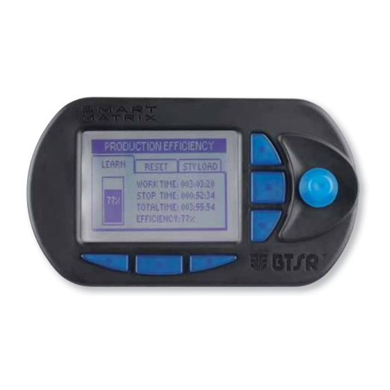
SMART MATRIX TWIST Operation Interpretation of Operating Screens • System running • No error detected • 7 active sensors out of 7 • Efficiency 100% • 7 sensors detected the Twist L error • 0 active sensors out of 7 •... -
Page 35: Smart Matrix Twist Menu Structure
Struttura dei Menu SMART MATRIX TWIST SMART MATRIX TWIST Menu Structure Error Run Status Error indication Main Menu (*) Style Configuration (*) System Error/Styles Configuration (*) Scanning (*) After one minute of idling, it automatically returns to Run status. In the description of the various functions, the following graphic symbols will be used: Select the desired option and click to confirm. -
Page 36: Sensor Configuration And Numbering
1 (e.g. 7) and confirm. • Point the symbol of 2 Board and so on for all the Boards used. FIRST BOARD Once you have configured all the Boards. SAVE to save the settings. SMART MATRIX TWIST - 2-10 -... - Page 37 Skim the touch light of the indicated sensor and continue with the numbering of all the remaining sensors . At the end of the numbering operation, the configuration menu will re-appear. To return to SETUP menu. SMART MATRIX TWIST - 2-11 -...
- Page 38 Note 1: To select the coordinates of the sensor you wan to renumber (e.g. A4), operate as follows: • Turn the selector to select the desired side or sensor. Press the selector to alternately switch between side and sensor selection. • Select the sensor A4. SMART MATRIX TWIST - 2-12 -...
-
Page 39: Smart Matrix Code
Select MATRIX CODE. Choose the SMART MATRIX identification code and activate the save function. SAVE to save the choice, BACK to return to the previous screen without saving, EXIT to return to menu. SMART MATRIX TWIST - 2-13 -... -
Page 40: Output Configuration On Sm-Din/Smart Matrix
(either Normally Open = NO, or Normally Closed = NC), then click to confirm. Point and select in sequence the EXT 3, EXT 2 signals and set the relevant polarity. Then point the window header (IN) and click to select it. SMART MATRIX TWIST - 2-14 -... - Page 41 During the saving operation a LOAD I/O CONFIG… message briefly appears Select MATRIX. Configure the output relay contact of SMART MATRIX terminal as or NC. To activate the save function. SMART MATRIX TWIST - 2-15 -...
- Page 42 Note 1: The value increment/decrement resolution can be changed using the direct activation buttons B1, B2, B3. Setting example: ACQ.TIME: No push button pressed: resolution x1 (increment/decrement by 1). Resolution x10 (increment/decrement by 10). Resolution x100 (increment/decrement by 100). Resolution x1000 (increment/decrement by 1000). SMART MATRIX TWIST - 2-16 -...
-
Page 43: Keycode Setting
Administrator Password Press EDIT Select PASSWORD and set the administration password turning the selector and clicking to confirm each character and move to the next one. To confirm the entered password SAVE to confirm. SMART MATRIX TWIST - 2-17 -... - Page 44 Press EDIT button to edit (change) the access rights of selected user. Change the configuration of menus and options available to the selected user (SETUP MENU, STYLE MODIFY, STYLE LOAD, RESET COUNTERS, SENSORS ON/OFF) SMART MATRIX TWIST - 2-18 -...
- Page 45 RESET DOFF buttons within the Error Counter Display screen) SENSORS ON/OFF Sensor activation/deactivation (with the ON/OFF button within the Sensors Histogram) The user may access exclusively the functions selected ( ) within the FEATURES window. SMART MATRIX TWIST - 2-19 -...
-
Page 46: Communication Test
Global efficiency index. Like for GLOBAL option, but referred to the selected Board (e.g: BOARD NUMBER:1) Efficiency index of Board 1. BACK to return to the previous screen without saving, EXIT to return to menu. SMART MATRIX TWIST - 2-20 -... -
Page 47: Sensors Test
SENSOR TEST Enter the SETUP menu. Select TEST COM. Select SENSOR TEST. Turn the selector and check that only the sensor installed at Side, Position Section coordinates indicated on Smart Matrix display is blinking red. SMART MATRIX TWIST - 2-21 -... -
Page 48: Service Functions
POSITION 3 to 3 on side B. to upgrade all sensors of section 3, side A and B, set: from SECTION 3 to 3 on side ALL. Once you have selected the sensor(s) you want to upgrade, press START. SMART MATRIX TWIST - 2-22 -... - Page 49 Note: At any time, you can interrupt the upgrading process, pressing the STOP button. return to SERVICE menu. How to Read the Parameters → → SETUP SERVICE SENS. READ Currently Programmed on Sensors Enter the SETUP menu. Select SERVICE. Select SENS. READ. SMART MATRIX TWIST - 2-23 -...
- Page 50 To return to SERVICE menu. For more details about the meaning of each parameter, please refer to Section 3 “Characteristics of IS3.. Sensors”. For more details about the parameter setting procedures, please refer to STYLE menu. SMART MATRIX TWIST - 2-24 -...
- Page 51 (i.e. the version that would be loaded to the sensors with the SENS UPG function). → Paramters configured on Board # (see Setup I/O Config → Boards function). To return to SERVICE menu. SMART MATRIX TWIST - 2-25 -...
- Page 52 ↔ For more details about the Master/Slave function, please refer to “Smart Matrix Master Smart Matrix Slave Connection” on Section 1. Enter the SETUP menu. Select SERVICE. Select MASTER. To return to SERVICE menu. SMART MATRIX TWIST - 2-26 -...
-
Page 53: Matrix Lcd Adjustment
Adjust: • CONTRAST, • BRIGHTNESS, • DISPLAY AUTO OFF To activate the save function. SAVE to save the settings, BACK to return to the previous screen without saving, EXIT to return to the menu. SMART MATRIX TWIST - 2-27 -... -
Page 54: Information About Smart Matrix Twist
Information about SMART MATRIX TWIST SETUP → INFO This function allows you to detect the Hardware, Firmware, OS and Boot Program versions. These values shall be communicated to BTSR Service Department when requiring technical support to solve specific problems. Enter the SETUP menu. -
Page 55: Style Parameters Programming
Section 3: “IS3.. Sensors Features”. Select the STYLE menu item. The example shown indicates that the Smart Matrix TWIST terminal currently contains 2 styles (TWIST1 and TWIST2); the other positions [3 to 100] are empty Select the desired position (for instance position 1 TWIST1): Click to highlight MACHINE. - Page 56 EXIT to return to menu STYLE without saving. Enter the name you want to assign to the new style (e.g. TWIST3), then hold the selector pressed for 3 seconds. SMART MATRIX TWIST - 2-30 -...
- Page 57 If you change a style currently loaded on one or more machine sensors, after the saving the modified style will automatically be loaded to the involved sensors. SMART MATRIX TWIST - 2-31 -...
-
Page 58: Style Loading
3, side A and B, set: from SECTION 3 to 3 on side ALL. Once you have selected the sensor(s) you want to update, press LOAD. During the loading process, a LOADING STYLE… message will briefly appear SMART MATRIX TWIST - 2-32 -... -
Page 59: Scan Error Function
L) while the A2 sensor is detecting a communication error (Err Com) To go to the “Error Counter Display” To go to the ”Sensor Histogram” To exit the function To go back to the menu. SMART MATRIX TWIST - 2-33 -... -
Page 60: Scan Styles Function
In this third example the TWIST3 style is loaded on A5 and A6 sensors. Total positions:2. If more sensor intervals are present you can scroll the position list by means of the arrow keys. To go back to the menu. SMART MATRIX TWIST - 2-34 -... -
Page 61: Sensor Histogram
POS:1 and the value read by POS:1 is TPM: 24. To change the visualization scale (zoom +) To change the visualization scale (zoom -) To switch to the display SMART MATRIX TWIST - 2-35 -... - Page 62 To change the visualization scale (zoom +) Possibility of activating/deactivating the sensor via software To change the visualization scale (zoom -) To choose the visualization type (TPX or CV%) Sensor status (Run, Disab(sw), Tens L, etc.) To leave the function. SMART MATRIX TWIST - 2-36 -...
-
Page 63: Error Counter Display
(they can be individually reset) Pressing the selector you can select an individual item and reset it, if necessary, by pressing the B4 button. To leave the function. Select SINGLE POSITION. (Counters referred to the individual position) SMART MATRIX TWIST - 2-37 -... - Page 64 Error count related to the currently processed package (they can be individually reset) Pressing the selector you can select an individual item and reset it, if necessary, by pressing the B4 button. SMART MATRIX TWIST - 2-38 -...
- Page 65 RAM data loss on SM-DIN Board number #. EEPROM data loss on SM-DIN Board number #. Error detected on an I/O port of SM-DIN Board number #. Communication error with the IS3.. sensor at the indicated position. SMART MATRIX TWIST - 2-39 -...
-
Page 66: Errors Shown On Display Of Sm-Din Boards
The module cannot determine the logical level of the external input signals (EXT). Communication Error The module cannot communicate with one or more IS3.. sensors Programming Error The module was not able to program one or more parameters on one or more IS3.. sensors SMART MATRIX TWIST - 2-40 -... -
Page 67: System Components
System Components... -
Page 69: Is3X/Tts Sensor Features
2. Fig.2 The TT mode is suitable for non hairy yarns (tyrecord) showing a regular profile, while the TB mode is suitable for hairy yarns that could alter the profile. SMART MATRIX TWIST - 3-1 -... - Page 70 Close the small cover and secure the sensor using M3 screws. Ensure that the yarn runs in the middle of detection area SMART MATRIX TWIST - 3-2 -...
- Page 71 To switch the touch light, just skim it with a finger. • 2 signally Leds (green ad red) indicating the sensor’s status (initial numbering status, normal operation status, failure condition and type of failure). Touch Light (embedded green and red Leds) SMART MATRIX TWIST - 3-3 -...
- Page 72 Indicates a sensor fault (e.g. Loss of stored data). Red LED FLASHING Try to reprogram the sensor. If the fault remains, replace the sensor For more details, please refer to paragraph “Parameters that affect the sensor detection features”. SMART MATRIX TWIST - 3-4 -...
- Page 73 Sensor not powered (check connections). Red LED OFF Sensor de-activated (“Touch Light” skimmed); to re- activated it, skim again the “Touch Light”. For more details, please refer to paragraph “Parameters that affect the sensor detection features”. SMART MATRIX TWIST - 3-5 -...
- Page 74 Pulse signal (PULSE 2S) or 10 seconds Pulse signal (PULSE 10S). Electrical Characteristics of STOP Signal Protected against short circuit Max DC current at collector: 200 mA Max peak current at collector: 500 mA Vce = 1,2V with I_collector = 500 mA SMART MATRIX TWIST - 3-6 -...
-
Page 75: Parameters That Affect The Sensor Detection Features
/ discriminate the presence of the above mentioned defects. The variables of this program are represented by the settings connected to the article which is being controlled, i.e. the settings that can be defined, changed and loaded into the sensors by means of the SMART MATRIX TWIST system:... - Page 76 Packages with shorter working times are not counted, or better, they are counted as "false doffing". K factor Twist division factor depending on the number of twisting yarns. Selecting the “reverse K” option the K value has the meaning of: multiplication factor SMART MATRIX TWIST - 3-8 -...
- Page 77 Either Manual through (Touch Light) or Automatic if Reset Manual/Auto parameter is set to Auto Note: When the sensor is de-activated, the STOP Output is always in Normal Operation condition therefore, in case of NO configuration it will always be an open circuit. SMART MATRIX TWIST - 3-9 -...
- Page 78 (the yarn runs normally and the number of twisting is within the programmed range TPX MAX and TPX MIN) Delay Control = Delay programmable via software Failure Reset = Either Manual through (Touch Light) or Automatic if Reset Manual/Auto parameter is set to Auto SMART MATRIX TWIST - 3-10 -...
- Page 79 DISTRIBUTOR BTSR International S.p.A. Via S. Rita 21057 OLGIATE OLONA (VA) Tel. 0331-323202 Fax 0331-323282 Internet: www.btsr.com REV. 1.2 – 01/12...
Need help?
Do you have a question about the SMART MATRIX TWIST and is the answer not in the manual?
Questions and answers