
Subscribe to Our Youtube Channel
Related Manuals for btsr SMART WARP


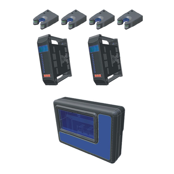
Summary of Contents for btsr SMART WARP
- Page 1 SMART WARP & IS3F-485 YARN CONTROL SYSTEM Operating Manual ENGLISH Rev. 1.0 – January 2006...
- Page 2 SMART KNIT – Rev. 1.0 – January 2006 Copyright 2006 - BTSR - All rights reserved. This manual is intended for the users of SMART WARP yarn control systems. You are kindly recommended to carefully read the instructions reported in this manual before making the connections and use the system.
-
Page 3: Table Of Contents
A6 - KEYCOD - Access Password to Programming Menus (KSETUP) .............3.16 A6 - KEYCOD - Access Password to LEARN function (KLEARN) ..............3.16 A7 - TEST-COM - Test of Communication Line Between SMART WARP Terminal and SM-DIN Modules3.17 SMART WARP - i -... - Page 4 Display Signalings during the Control Process ..................... 3.22 Chapter 4 – TROUBLESHOOTING AND MAINTENANCE Troubleshooting ................................. 4.1 Machine Test ................................4.4 Ordinary Maintenance .............................. 4.4 Repairs..................................4.4 Updating the Software Version on SMART Terminals..................4.5 - ii - SMART WARP...
-
Page 5: Introduction
INTRODUCTION INTRODUCTION Congratulations for choosing a BTSR product. With our SMART WARP yarn control system, you got an innovative, unique solution, which offers you multiple advantages concerning the quality control of your production. SMART WARP has been designed for applications on large warping machines that use in continuous mode a large number of yarns (up to 2000) during the entire working cycle. - Page 6 Introduction Page intentionally left blank - I.2 - SMART WARP...
-
Page 7: Chapter 1 - Overview
Special Features of SMART WARP System The SMART WARP system has a set of unique features which make it a true microcomputer dedicated to programming/control of production and statistical analysis of technical faults. -
Page 8: General Features Of Smart Btsr Systems
The system automatically learns the sequence of yarns used by the textile machine. ! IS3 Sensors (Image Smart Scanning Sensor) (BTSR Patents) The sensors are connected to the SM-DIN modules in “daisy-chain” mode, thus making extremely easy the wiring operation. -
Page 9: Chapter 2 - Technical Data And Installation
Self-restoring fuse, 5A Power Supply Power supply voltage (*) 15..24 Vac ± 10% (by transformer) (*) The supply voltage to SMART WARP terminal is provided by the connection cable between terminal and SM-DIN interface module. SMART WARP - 2.1 -... -
Page 10: Sm-Din - Sensor Connection
Technical Data and Installation SM-DIN - Sensor Connection As described on chapter 1, the SMART WARP system can manage up to 2000 IS3 sensors, connected through SM-DIN interface modules (up to 20). Each module can manage up to 100 sensors distributed along 4 backbone lines. -
Page 11: Sm-Din Modules Interconnection
Technical Data and Installation SM-DIN Modules Interconnection SMART WARP - 2.3 -... -
Page 12: Electrical Interface
SM-DIN module nn – (identified by means of Edt function directly on SM-DIN module) Chain 1 - Sensors Max 100 sensors Chain 2 - Sensors identified by means of Device function (Setup → Config menu) Chain 3 - Sensors Chain 4 - Sensors - 2.4 - SMART WARP... -
Page 13: Chapter 3 - Operation
OPERATION SMART WARP Terminal Features As for all SMART BTSR systems, the operation of SMART WARP system is controlled by just 5 membrane buttons and it is monitored by a LCD graphic display, which guides the operator through all programming and administration phases of the system, by means of straight-forward messages which can be understood clearly and immediately. - Page 14 When the displayed lines refer to the menu items, the selected one is indicated with > the symbol (---) The presence of a flashing cursor indicates the position where the operator can enter an alphanumeric character or variable setting which will replace the value currently displayed. - 3.2 - SMART WARP...
- Page 15 P1 it is useless to press the RESET button, as the system is already in the main menu and it is not possible to select a higher level of the menu. SMART WARP - 3.3 -...
-
Page 16: Sm-Din Module Configuration
SM-DIN Module Configuration The SM-DIN sensor interface modules require the programming of 2 parameters only: Identification number of SM-DIN modules within the system (1 to 20) Communication speed (Baudrate) between SMART WARP and SM-DIN (115,2 or 57,6 Kbps) Procedure 3 sec. -
Page 17: Operating Signaling/Anomalies
The lighting of respective red leds indicates: FAST input inactive. SLOW input inactive. RESET input active. SM-DIN module in CONTROL status. Communication in progress between SM-DIN and SMART WARP. STOP output (AL2) active (led flashing). STOP output (AL1) active (led flashing). SM-DIN module powered SMART WARP... -
Page 18: Is3 Sensors Features
Green LED FLASHING Indicates a technical fault in the sensor(e.g. a loss of Red LED FLASHING stored data). Try to reprogram the sensor. If the fault remains, replace the sensor. - 3.6 - SMART WARP... -
Page 19: Settings That Affect The Sensor Detection Features
The SENS parameter allows the control of the sensor sensitivity level, depending on the article to be processed. It can be programmed to a value ranging between 1 and 10. The default value is 4. SMART WARP - 3.7 -... -
Page 20: Programming Examples For F_Start/F_Stop And Relevant Sensor Delays
In the presence of frequent errors detected by the sensors, it is suggested to gradually change such values until an optimal condition is achieved. - 3.8 - SMART WARP... -
Page 21: Automatic Adaptation Of Control Parameters To The Machine Speed
Operation Automatic adaptation of control parameters to the machine speed One of the main features of the SMART WARP system is the possibility of programming 2 different sets of control parameters (P_SLOW and P_FAST) and automatically switching from one set to the other depending on the status of two external input signals, provided by the textile machine (SLOW EXT and FAST EXT). -
Page 22: Preliminary Operations For Using The Smart Warp Terminal
If the CONTROL message appears, it means that the system correctly started the production control phase. (All the red Leds inside the buttons of SMART WARP terminal, as well as the Leds of SM-DIN Interface Modules turn off, except the CONTROL Leds). -
Page 23: Operating Sequences
Operation Operating Sequences The SMART WARP system allows you to carry out the following set of functions: Programming the parameters that affect the system operation, through a number of interactive menus. Activating a LEARN cycle, during which the sequence of yarns used by the "... -
Page 24: Functions Available From Setup Menu (Config)
Operation Functions available from SETUP menu (CONFIG) Setup/Programming Menu Main Menu Functions available from SETUP menu (P_SLOW / P_FAST) Setup/ Main Menu Programming Menu - 3.12 - SMART WARP... -
Page 25: A1 - Boards - Number Of Connected Sm-Din Modules (Boards)
* The product of the two values (ROW x COL) must not be greater than 1000, as it represents the number of sensors for each machine section (side A and side SMART WARP - 3.13 -... -
Page 26: A3 - Device - Sensors Numbering
Once all the sensors have a unique number assigned, the BOARD 01 DEVICE message re-appears. to start the numbering of sensors connected to SM-DIN module 02. to return to the CONFIG menu once all the sensors connected to all SM-DIN modules have been numbered. - 3.14 - SMART WARP... -
Page 27: A4 - Input - Configuration Of Input Signals
(NC) or normally open (NO) contact. to activate the function (parameter ST-1). to select NC or viceversa. to confirm the choice and move to parameter ST-2. to move to the configuration of Keycodes. to return to CONFIG menu. SMART WARP - 3.15 -... -
Page 28: A6 - Keycod - Access Password To Programming Menus (Ksetup)
WARNING: If you set a password (KSETUP and/or KLEARN), it is necessary to enter it each time you access the SETUP menu or the LEARN function. If you forget the access code it will be necessary to contact your BTSR reseller. - 3.16 - SMART WARP... - Page 29 Operation TEST - COM Test of Communication Line Between SMART WARP Terminal and SM- DIN Modules SETUP CONFIG TEST This function allows you to check the perfect operation of the communications line between the SMART WARP terminal and the connected SM-DIN modules.
-
Page 30: A7 - Test-Sensor - Test Of Individual Sensors
The test does not send any diagnostic message to the SMART WARP system display! The operator shall simply select the number of the desired sensor, within òthe map defined with the MAP function: "... -
Page 31: B1 - P_Slow - Configuration Of Detection Parameters With Slow Ext Input Active
Delay (reaction time) Allowed values: [5 ms ÷ 1,000 ms] Start Frequency Allowed values: [001 ÷ 010] Stop Frequency Allowed values: [001 ÷ 010] to select the P_FAST option. (*) This parameter can be de-activated (OFF) pressing SMART WARP - 3.19 -... -
Page 32: B2 - P_Fast - Configuration Of Detection Parameters With Fast Ext Input Active
Delay (reaction time) Allowed values: [5 ms ÷ 1,000 ms] Start Frequency Allowed values: [001 ÷ 010] Stop Frequency Allowed values: [001 ÷ 010] to return to SETUP menu. (*)This parameter can be de-activated (OFF) pressing - 3.20 - SMART WARP... -
Page 33: Learning Cycle (Learn)
To avoid evaluation mistakes (i.e. to consider a yarn running, while it is actually still), the Learn phase uses a special BTSR algorithm that makes such phase extremely accurate. In case of unstable sensor reading, an error message is displayed. -
Page 34: Display Signalings During The Control Process
Operation Display Signalings during the Control Process During the Control process, the display of the SMART WARP terminal as well as the display of SM-DIN modules may show various failure signaling messages. When the failure refers to a sensor two alternate screens appear which indicate the machine side (either Side A or Side B) and the co-ordinate (ROW/COL) of the sensor that detected the failure. -
Page 35: Chapter 4 - Troubleshooting And Maintenance
Stop Frequency settings. Alternate messages on condition display of SMART Sensor on Side X, terminal: Row aaa, Column UNCUT ROW aaa SIDE X COL bbb and message: on display of the involved MS-DIN module SMART WARP - 4.1 -... - Page 36 ! Repeat the Learn operation. phase. ! Try to change P_SLOW and P_FAST ERROR LEARN parameters. If the problem persists replace the on display of SMART SM-DIN module. terminal and message: on display of the involved MS-DIN module - 4.2 - SMART WARP...
- Page 37 If the fault is not included in the above table, please contact your local BTSR dealer, giving a detailed description of the fault and the conditions in which it occurred. When the BTSR Technical Service intervention is required,...
-
Page 38: Machine Test
During the learning cycle, pay attention not to touch the yarns and not to stop the machine. 3. At the end of the learning cycle the SMART WARP must automatically start the control phase (CONTROL nnnn displayed), where nnn indicates the number of sensors learnt with running yarn. -
Page 39: Updating The Software Version On Smart Terminals
Troubleshooting and Maintenance Updating the Software Version on SMART Terminals The software updating on BTSR SMART terminals is a relatively easy operation. However it must be carried out following scrupulously the instructions given in this manual and using the indicated tools to avoid damaging the equipment and/or microprocessor contacts. - Page 40 Troubleshooting and Maintenance Page intentionally left blank - 4.6 - SMART WARP...
- Page 41 DISTRIBUTOR BTSR International S.p.A. Via S. Rita 21057 OLGIATE OLONA (VA) Tel. 0331-323202 Fax 0331-323282 Internet: www.btsr.com REV. 1.0 – 01/06...
Need help?
Do you have a question about the SMART WARP and is the answer not in the manual?
Questions and answers