
Related Manuals for btsr TS5 Series


Summary of Contents for btsr TS5 Series
- Page 1 SMART 200 TSS & TS5 YARN CONTROL SYSTEM Operating Manual ENGLISH Rev. 2.0 – July 2003...
- Page 2 BTSR reserves the right to change in any time the contents of this manual, without notice. For any technical or commercial problem, please contact your local BTSR dealer or call directly BTSR customer service centre.
-
Page 3: Table Of Contents
Table of Contnents TABLE OF CONTNENTS TABLE OF CONTNENTS TABLE OF CONTNENTS TABLE OF CONTNENTS INTRODUCTION How to use this manual.............................. I.1 Symbols used ................................I.2 Chapter 1 - OVERVIEW System components ..............................1.1 System’s Operation Principles ..........................1.1 Special Features of SMART 200 TSS system......................1.1 General Features of SMART systems ........................1.2 Chapter 2 –... - Page 4 Indice Generale lk-ULK Enabling/Disabling the Touch Light button operation ............3.26 ST-NCO Configuring the level of STOP signal as Normally Closed or Normally Open ....3.27 EN-NCO Configuring the level of ENABLE signal as Normally Closed or Normally Open o ..3.28 D_CNTR Configuration of Sensor delay time before entering the Control status ......3.29 OFFSET Offset Configuration .......................3.30...
-
Page 5: How To Use This Manual
The SMART 200 TSS system has been designed to meet two different application typologies showing different requirements, even if both typologies are based on the yarn Tension control which is entrusted to the TS5.. series BTSR tension sensors. To manage the above mentioned application typologies, the system provided two... -
Page 6: Symbols Used
Indicates a particularly sensitive situation which could have an effect on the safety or proper operation of the system. TS5.. The TS5.. BTSR sensor family includes some variants indicated by the letters following the TS5.. term, and identifying the reference weight in grams, the type of eyelet used etc. - Page 7 Introduction Meaning of the Capital/Small Letters on Display Within the functions that provide two programmable alternative options, i.e.: !"System Working Mode (either TSS or TSQ) !"Normally Open or Normally Closed Contact !"Enabled/Disabled Condition !"Pulse/Continuous Signalling, etc. The letters shown on display as capital letters indicate the currently active choice, while the small letters refer to the possible alternative choice.
- Page 8 Introduction Page intentionally left blank - I.4 - SMART 200 TSS...
-
Page 9: Chapter 1 - Overview
Overview 1 1 1 1 - - - - OVERVIEW OVERVIEW OVERVIEW OVERVIEW System components The SMART 200 TSS system consists of a control/programming terminal and a variable number of TS5.. type sensors (up to 200) connected to the terminal using specific interface cables. -
Page 10: General Features Of Smart Systems
8/12/16 TS5.. sensors in graphic mode. General Features of SMART systems !"TS5.. Sensors (Tension Smart Scanning Sensor…) (BTSR Patents) The TS5.. sensors are connected to the SMART control terminal using specific single connector and doubler cables. -
Page 11: Chapter 2 - Technical Data And Installation
Technical data and installation 2 2 2 2 – – – – TECHNICAL DATA AND INSTALLATION TECHNICAL DATA AND INSTALLATION TECHNICAL DATA AND INSTALLATION TECHNICAL DATA AND INSTALLATION Technical Features SMART 200 TSS Terminal Power supply voltage 24 Vdc ± 10% Maximum Absorption 100 mA Dimensions... -
Page 12: Interface Connectors On Smart 200 Tss
Technical data and installation Interface Connectors on SMART 200 TSS Concerning all electrical systems, it is a recommended rule to ensure that the ground cable (GND) is connected to the sensor support. - 2.2 - SMART 200 TSS... -
Page 13: Connection Example For Generic Applications On Rewinding, Doubling Cone Winder Machines, Etc. (Tss)
Technical data and installation Connection Example for Generic Applications on Rewinding, Doubling Cone Winder Machines, etc. (TSS) Concerning all electrical systems, it is a recommended rule to ensure that the ground cable (GND) is connected to the sensor support. SMART 200 TSS - 2.3 -... -
Page 14: Connection Example For Generic Applications On Warping Machines, Quilting, Embroidery Machines (Tsq)
Technical data and installation Connection Example for Generic Applications on Warping Machines, Quilting, Embroidery Machines (TSQ) Concerning all electrical systems, it is a recommended rule to ensure that the ground cable (GND) is connected to the sensor support. - 2.4 - SMART 200 TSS... -
Page 15: Connection Cables And Power Supply Devices
Connection Cables and Power Supply Devices To correctly install the SMART 200 TSS system and sensors, it is necessary to use a certain number of connecting cables provided by BTSR; their length and type depend on the specific requirements and application types. - Page 16 Technical data and installation Page intentionally left blank - 2.6 - SMART 200 TSS...
-
Page 17: Chapter 3 - Operation
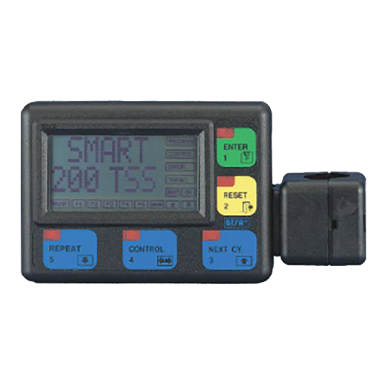
OPERATION SMART 200 TSS Terminal Features As in all SMART BTSR systems, the operation of SMART 200 TSS system is controlled by just 5 membrane buttons and it is monitored by a LCD graphic display, which guides the operator through all programming and administration phases of the system, by means of straight-forward messages which can be understood clearly and immediately. - Page 18 Operation ENTER Button It allows you to activate the function selected from the menu (indicated by the > symbol ), to move to the programming of the displayed function or to confirm the setting value displayed on the messages screen. RESET Button It allows you to return to the previous level of the menu (next upper level), without continuing with the currently selected function, or without confirming the value of...
- Page 19 Operation Operator’s Message Area. The menu choices, or settings for the selected function during programming or SMART setup phase of the system as well as service messages are displayed with large size 200 TSS fonts (1.5 x 0.8 cm), easy to read even from a distance, when the system is running normally.
-
Page 20: Ts5.. Sensor Features
Operation TS5.. Sensor Features The TS5.. devices are intelligent sensors able to detect, due to sophisticated control technique, the tension applied to the yarn being controlled, signalling possible anomalies about the tension itself. The tension exerted by the yarn on sensor’s loafing cell ((depending on the feeding tension of the yarn itself), is detected by the electronics of the sensor and converted by the built-in DSP (Digital Signal Processor) into a digital signal that can be interpreted both by the TS5.. -
Page 21: Ts5.. Sensor Types
Operation TS5.. Sensor Types The TS5.. sensors are available in various typologies to meet specific needs of individual installations/applications. The following diagram shows a detailed coding rule of the available sensors, depending on possible variables. Example: TS5/D500DD = TS5.. sensor, 500 grams weight, with model DD eyelet, Diamond finishing. -
Page 22: Technical Characteristics Of Ts5.. Sensor
Operation Technical Characteristics of TS5.. sensor Sizes (mm) - 3.6 - SMART 200 TSS... -
Page 23: Electrical Connections
Operation Electrical Connections +VCC STOP Green White White RX/TX+ Yellow Uscita Anal. Brown RX/TX- Black Enable Blue Mounting positions SMART 200 TSS -3.7 -... -
Page 24: Interface Specification
Operation Interface specification The TS5.. sensors communicate with the external world by means of the following signals: !" 1 Output signal (STOP) programmable via software as Normally Open (NO) or Normally Closed (NC) !" 1 Analogue Output signal variable depending on yarn tension !"... -
Page 25: Interpretation Of The Signaling Lights Located On The Sensors
Operation The following figure shows an example, in case of ENABLE signal programmed as NO. The sensor signals a defect (red LED blinking) and activates the STOP output. The ENABLE signal is activated while The STOP signal is still active. The sensor immediately releases the STOP signal, but maintains the defect signalling (red LED blinking). -
Page 26: Parameters That Affect The Sensor Detection Features
Operation Parameters that affect the sensor detection features The TS5.. series sensors are microprocessor based electronic sensors capable of detecting the most common types of yarn tension failures: !" Positive/negative threshold levels exceeded !" Positive/negative peak levels exceeded !" Missing Yarn The yarn running inside the sensor touches the loading cell that moves horizontally depending on the tension applied to the yarn itself. - Page 27 Operation TENS L This parameter indicates the Min Threshold Value (expressed as negative percentage value) with respect to the reference tension TENS, below which a failure condition will be signaled. The following two values must be specified. !" ERROR % = Negative error percentage (min threshold) with respect to the nominal tension TENS !"...
-
Page 28: Other Factors That May Affect The Control
Operation Other factors that may affect the control DELAY CONTROL Is the sensor waiting time before starting the control process, namely the time needed to the machine to reach the set speed (Programmable as 1 to 250 seconds). LOCK/UNLOCK It defines the Touch Light button operating mode: The button is enabled for the Automatic Numbering procedure only. - Page 29 Operation ENABLE NO-NC It defines the operating mode of the ENABLE input: The ENABLE input is normally open and, if it is connected to ENABLE NO: ground you obtain the de-activation of the Stop signal and the sensor exclusion. When you release the ENABLE input, the TS5.. sensor resumes the control after a wait time corresponding to Delay Control (green LED flashing).
-
Page 30: Preliminary Operations For Using The Smart 200 Tss Terminal
Power on the system and check that the graphic display shows sequentially, for a Start few seconds, the screens shown on the left side of this page: (BTSR Logo) (Type of SMART system) (Installed software version) If the display is blank please refer to “Troubleshooting” chapter”. -
Page 31: Operating Sequences
Operation Operating Sequences The SMART 200 TSS system allows the following set of functions to be carried out. Univocal identification of each sensor by means of an automatic numbering procedure. Programming, modifying, controlling and saving the values related to the "... -
Page 32: Enabling The Setup Menu Functions (Config)
Operation Enabling the SETUP Menu Functions (CONFIG) - 3.16 - SMART 200 TSS... -
Page 33: Enabling The Setup Menu Functions (New, Modify, Erase)
Operation Enabling the SETUP Menu Functions (NEW, MODIFY, ERASE) Enabling the WORK Menu Function SMART 200 TSS -3.17 -... -
Page 34: Enabling The Graph Menu Function
Operation Enabling the GRAPH Menu Function - 3.18 - SMART 200 TSS... -
Page 35: Control Function (With Side Option Disabled)
Operation CONTROL Function (with SIDE option disabled) SIDE Enabled SIDE Disabled Meaning D TOT L TH xxx DEV TOT TH xxx Total Number of “Tension High” failures D TOT L TL xxx DEV TOT TL xxx Total Number of “Tension Low” failures D TOT L PH xxx DEV TOT PH xxx Total Number of “Peak High”... -
Page 36: Device Parameters Setting For Initial Installation
Operation DEVICE - Parameters setting for Initial installation SETUP CONFIG DEVICE During the initial installation, this function allows the automatic numbering of the sensors connected to the system. Once the function has been carried out the system will be able to identify each one of the connected sensors, in univocal mode and with a progressive number (from 1 to 200). - Page 37 Operation Single Sensor Numbering If you need to either replace a single sensor or add a new sensor, the system gives you the possibility to operate only on the involved sensor, without having to repeat the global numbering procedure. When the display shows the DEVICES XXX screen, press to start the single sensor numbering.
-
Page 38: Side Machine Sides Definition
Operation SIDE - Machine Sides Definition SETUP CONFIG SIDE This function allows you to logically subdivide the machine into two logical sides (A and B) to make easier the TS5.. sensor location. The subdivision function can be disabled using the OFF option. The sensor numbering is indicated in different way depending on the enabling/disabling condition of this option.: Examples:... -
Page 39: Tss - Q Application Type Configuration - Tss/Tsq
Operation TSS - Q - Application Type Configuration – TSS/TSQ SETUP CONFIG This function allows you to configure one of the two operating mode available on SMART 200 TSS terminal. !"TSS: Simple article’s Data Base with related Tension Control parameters to be loaded on connected TS5.. -
Page 40: Mo-Ctr Configuring The System Operation In Either Monitor Mode Or Control Mode
Operation MO-CTR - Configuring the system operation in either MONITOR mode or CONTROL mode SETUP CONFIG MO-CTR This function allows configuring the System Operation mode when a failure is detected. Depending on the type of failure detected, the Stop Output and/or the LEDs (red - green) lighting with a predefined sequence are activated. - Page 41 Operation Only if you choose the Monitor mode with SIDE option enabled (A-B) XXX = First sensor of the section to be programmed (on side A or B). YYY = Last sensor of the section to be programmed (on side A or B). moves the cursor from XXX field to YYY field increases the field pointed by the cursor decreases the field pointed by the cursor...
-
Page 42: Lk-Ulk Enabling/Disabling The Touch Light Button Operation
Operation lk-ULK - Enabling/Disabling the Touch Light button operation SETUP CONFIG lk-ULK This function allows Enabling/Disabling the operations of Touch Light button for sensor reset in case of alarm. The Touch Light button, however, is always enabled for the Automatic Sensor Numbering, independently of the LOCK/UNLOCK condition set with this function. -
Page 43: St-Nco Configuring The Level Of Stop Signal As Normally Closed Or Normally Open
Operation ST-NCO - Configuring the level of STOP signal as Normally Closed or Normally Open SETUP CONFIG ST-NCO This function allows defining the operating mode of the STOP output in order to meet the application needs. The signal may be configured as Normally Open (NO) or Normally Closed (NC). -
Page 44: Nco Configuring The Level Of Enable Signal As Normally Closed Or Normally Open
Operation EN-NCO - Configuring the level of ENABLE signal as Normally Closed or Normally Open SETUP CONFIG EN-NCO This function allows defining the operating mode of the ENABLE input in order to meet the application needs. The signal may be configured as Normally Open (NO) or Normally Closed (NC). -
Page 45: D_Cntr Configuration Of Sensor Delay Time Before Entering The Control Status
Operation D_CNTR - Configuration of Sensor delay time before entering the Control status SETUP CONFIG D_CNTR This function allows you to delay the sensor entry into the yarn quality control status (CONTROL). This delay can be freely set (from 1 to 250 seconds) depending on the needs, for instance to give the operator enough time to prepare the position and the machine to reach the rated speed. -
Page 46: Offset Offset Configuration
Operation OFFSET - Offset Configuration SETUP CONFIG OFFSET This function allows you to define the range of sensors on which to adjust the Offset, i.e. the yarn absence condition in the actual machine operation environment. Yarn absence = 0 grams tension = NOYARN condition. The TS5.. -
Page 47: Abs / Relabs Configuring The Sensor Operating Mode
Operation ABS / RELABS Configuring the Sensor Operating Mode SETUP CONFIG ABS / RELABS This function allows selecting the operating mode of connected sensors (either Absolute or Relative - Absolute). For further information, please refer to the ABS / RELABS modes description on page 3.13. -
Page 48: Key-St Password To Access Setup And Work Menus
WARNING: If you set a password (Keycode) it is necessary to enter it each time you access SETUP and WORK. If you forget the access code it will be necessary to contact your BTSR reseller. - 3.32 - SMART 200 TSS... -
Page 49: Key-Lr Password To Access Learn Function
Menu. WARNING: If you set a password (Keycode) it is necessary to enter it each time you access LEARN function. If you forget the access code it will be necessary to contact your BTSR reseller. SMART 200 TSS -3.33 -... -
Page 50: Clock Reading/Setting The Printer Clock-Calendar (Rtc)
Operation CLOCK - Reading/Setting the Printer Clock-Calendar (rtc) SETUP CONFIG CLOCK This function allows you to read, and setup, if necessary, the date and time that will be printed on production reports with the PRINT REPORT function. Once you have selected the CLOCK function from CONFIG menu, press have access to the function. -
Page 51: Sensor Test Sensors Test
Operation SENSOR TEST - Sensors Test SETUP CONFIG TEST SENSOR This function gives you the possibility to check communications between the SMART 200 TSS terminal and (one by one) each of the connected sensors. In this way it is possible to check that: !"... -
Page 52: Com Test Testing The Efficiency Rate Over The Communications Line Between The Smart 200 Tss Terminal And Sensors
Operation COM TEST - Testing the Efficiency Rate over the Communications Line between the SMART 200 TSS Terminal and Sensors SETUP CONFIG TEST This function allows you to check the perfect operation of the communications line between the SMART 200 TSS Terminal and connected Sensors. It is advisable to run this check during the first testing phase (immediately after installation) and each time random problems occur in the system operation, which may have been caused by inefficient communications between the Sensor and the... -
Page 53: Vers - Upg Test Of Software Version And Sensor's Version Updating
The updating procedure is effective only if all the sensors have a software version ≥ 2.0 and it must be carried out only if strictly necessary, for instance upon indication of your BTSR distributor. Press until the TEST CONFIG menu option is displayed. - Page 54 Operation Select the range of sensors to be updated using Press to execute the updating The selected sensors, will be automatically updated, one after the other, and the field xxx will automatically increase until it reaches the value set as yyy in the previous step.
-
Page 55: New Creating A New Article
Operation NEW - Creating a New Article SETUP This function allows creating a new article and associating to such article the quality control parameters that will be used by TS5.. sensors during the processing phase of the article itself. For each parameter you will have to program the values summarized in the following table (the values into brackets [..] are the default ones). - Page 56 Operation Now you will have to program the sequence of tension control parameters related to the article being created: !" TENS !" TENS H !" TENS L !" PEAK H !" PEAK L !" NOYARN Parameters TENS H, TENS L, PEAK H, PEAK L and NOYARN can be selectively disabled (OFF) or re-enabled, pressing the CONTROL button.
-
Page 57: Tens Creating A New Article Reference Nominal Tension
Operation TENS - Creating a New Article Reference Nominal Tension SETUP TENS Press to have access to the function. Set the reference nominal tension for the article being created, using [Default: 5.0 gr.] Press the entered value. This screen, displayed for a few seconds indicates that the previously set parameter has been programmed correctly. -
Page 58: Tens H
Operation TENS H - Creating a New Article Characteristics of “Max Tension Threshold Exceeded” failure SETUP TENS H to have access to the function. Press Press to continue, or press to disable/enable this parameter. Set the increasing percentage with respect to the reference nominal tension that shall be interpreted as max tension threshold exceeded, using [Default: +30%] Press... -
Page 59: Tens L
Operation TENS L - Creating a New Article Characteristics of “Min Tension Threshold Exceeded” failure SETUP TENS L to have access to the function. Press to continue, or press to disable/enable this parameter. Press Set the decreasing percentage with respect to the reference nominal tension that shall be interpreted as min tension threshold exceeded, using . -
Page 60: Peak H
Operation PEAK H - Creating a New Article Characteristics of “Max Tension Peak Exceeded” failure SETUP PEAK H Press to have access to the function. to continue, or press to disable/enable this parameter. Press Set the increasing percentage with respect to the reference nominal tension that shall be interpreted as max tension peak exceeded, using [Default: +50%] Press... -
Page 61: Peak L
Operation PEAK L - Creating a New Article Characteristics of “Min Tension Peak Exceeded” failure SETUP PEAK L Press to have access to the function. Press to continue, or press to disable/enable this parameter. Set the increasing percentage with respect to the reference nominal tension that shall be interpreted as min tension peak exceeded, using [Default: -50%] Press... -
Page 62: Noyarn
Operation NOYARN - Creating a New Article Characteristics of the Yarn Missing Failure SETUP NOYARN Press to have access to the function. to continue, or press to disable/enable this parameter. Press Set the increasing percentage with respect to the reference nominal tension that shall be interpreted as yarn missing, using [Default: -75%] Press... -
Page 63: Modify Modifying An Existing Article
Operation MODIFY - Modifying an existing Article SETUP MODIFY This function allows modifying one or more article's parameters previously created, when it is supposed that the previous value assigned to the parameter does not guarantee the optimum operation characteristics. The procedure is identical to that already described for creating a new article …. -
Page 64: Scan Displaying Articles Currently Loaded In The Sensors
Operation SCAN - Displaying Articles currently loaded in the sensors WORK SCAN This function allows the visualization of articles which are loaded into the sensors connected to SMART 200 TSS system. to have access to the function. Press The screen shows the first article loaded in the sensors connected to the SMART 200 TSS system. -
Page 65: Load Loading An Article To Sensor Memory
Operation LOAD - Loading an article to sensor memory WORK LOAD This function allows loading of an article (more specifically the settings of the article) on a specified range of sensors connected to the SMART 200 TSS system. The sensors must have been previously declared and numbered using the CONFIG DEVICE function. - Page 66 Operation Press twice to return to the XXX LOAD screen and select a new article to load. Press three times to return to the Main Menu. Only for TSS operating mode and RELABS sensor working mode If the operating mode is TSS and the sensor working mode is RELABS, after the article’s parameters loading, the self learning (LEARN) procedure will be activated.
-
Page 67: Unload Unloading Articles From The Sensor Memory
Operation UNLOAD - Unloading articles from the sensor memory WORK UNLOAD This function allows you to unload an article which was previously loaded using the LOAD function, from a range of sensors. It is not necessary to specify any range of sensors as the function automatically unloads the settings of the selected article from the range of sensors on which the article itself was loaded. -
Page 68: Bar Graph
Operation BAR GRAPH - Graphic visualisation of the Tension Detected by each TS5.. device GRAPH BAR GRAPH This function allows you to display in real time the tension detected by each TS5.. sensor. Tension Detected by device yy Device number selectable using Horizontal bar showing in PEAKL limit... -
Page 69: Istog Graph Graphic Visualization (Comparison) Of The Tensions Detected By Multiple Ts5
Operation ISTOG GRAPH - Graphic visualization (comparison) of the Tensions detected by multiple TS5.. devices GRAPH # ISTOG GRAPH This function allows you to compare, by means of Histograms, the tensions detected by a given number of TS5.. (up to 16) sensors. You will have the possibility to choose the reference device (against which to perform the comparison) as well as the number of devices (Histogram’s bars) to be compared (8, 12 or 16). - Page 70 Operation Once you have selected the >GRAPH item from main menu press to have access to the function. Press to select the ISTOG-GRAPH function.. Press to start the function. Choose the reference sensor (nnn) using Choose the number of bars (sensors) to be displayed (8-12-16) using 3 sec = to select the desired machine side (either A or B), if the SIDE function is active.
-
Page 71: Learn Procedure For Tsq Operating Mode
Operation LEARN - Procedure for TSQ Operating Mode CONTROL LEARN In the TSQ operating mode (beam warping frame, seamers, quilting machines, etc..) it is necessary to perform a learning cycle to detect the sensors where the yarn is actually running. In this way the SMART 200 TSS system may exclude from the control the sensors which are not used for a particular yarn processing operation. - Page 72 Operation At the end of the learning phase (whose duration is 3 times the value programmed as “DELAY CONTROL”), the flashing CONTROL message re-appears and the green Leds remain permanently lit on the sensors where the yarn running was detected (within the setup tolerance limits). These will be the sensors enabled during the subsequent working phases, while the other sensors where the correct yarn running was not detected, will have the green Led off and will be excluded from the control.
-
Page 73: Print Report Production Report Printing
Operation PRINT REPORT - Production Report Printing CONTROL PRINT? REPORT This function allows you to print a report containing the summary of TENS, TENS H, TENS L, PEAK H and PEAK L, NOYARN fault counters for each machine position. During the counter visualization phase, pressing the key, you will have access to the PRINT? REPORT function Press... - Page 74 Operation Production Report Example - 3.58 - SMART 200 TSS...
-
Page 75: Chapter 4 - Troubleshooting And Maintenance
DEV XX screen If the fault is not included in the above table, please contact your local BTSR reseller, giving a detailed description of the kind of fault and the conditions in which it occurred. In the case where the... -
Page 76: Ordinary Maintenance
For cleaning purposes, do not use solvent, but rather a soft cloth dampened with neutral detergent or alcohol. Repairs Any repair intervention on the SMART 200 TTS terminal must be executed by specialised personnel from BTSR. Any intervention attempt by non authorised personnel, voids the warranty terms. - 4.2 -... -
Page 77: Updating The Software Version On Smart Terminals
Troubleshooting and Maintenance Updating the Software Version on SMART Terminals The software updating on BTSR SMART terminals is a relatively easy operation. However it must be carried out following scrupulously the instructions given in this manual and using the indicated tools to avoid damaging the equipment and/or microprocessor contacts. -
Page 78: Product Summary Tables
Troubleshooting and Maintenance Product Summary Tables To make the creation/modification of articles easier and/or to speed up the operation of restoring the configuration values, it is suggested to take note of the defined settings for each article, which have been created. The following tables are intended to help you in this task. - Page 79 Troubleshooting and Maintenance Article ………………. TENS …………………. Parameter ERROR% TIME TENS H TENS L PEAK H PEAK L NOYARN Article ………………. TENS …………………. Parameter ERROR% TIME TENS H TENS L PEAK H PEAK L NOYARN Article ………………. TENS …………………. Parameter ERROR% TIME TENS H...
- Page 80 Troubleshooting and Maintenance Page intentionally left blank - 4.6 - SMART 200 TSS...
-
Page 81: Appendix A - Quick Reference
Appendix A - Quick Reference QUICK REFERENCE QUICK REFERENCE QUICK REFERENCE QUICK REFERENCE The following flow-charts show briefly the operating sequences which are required to complete all the functions available on the SMART 200 TSS system. The use of the quick reference guide supposes that the user has already acquired a certain ability in handling the system, therefore there are no detailed explanations of each screen shot;... - Page 82 Appendix A - Quick Reference Symbols Key A.2 - SMART 200 TSS...
- Page 83 Appendix A - Quick Reference Symbols Key SMART 200 TSS - A.3 -...
- Page 84 Appendix A - Quick Reference Symbols Key A.4 - SMART 200 TSS...
- Page 85 Appendix A - Quick Reference Symbols Key SMART 200 TSS - A.5 -...
- Page 86 Appendix A - Quick Reference Symbols Key A.6 - SMART 200 TSS...
- Page 87 Appendix A - Quick Reference Symbols Key SMART 200 TSS - A.7 -...
- Page 88 Appendix A - Quick Reference Symbols Key A.8 - SMART 200 TSS...
- Page 89 Appendix A - Quick Reference Symbols Key SMART 200 TSS - A.9 -...
- Page 90 Appendix A - Quick Reference Symbols Key A.10 - SMART 200 TSS...
- Page 91 Appendix A - Quick Reference Note: SMART 200 TSS - A.11 -...
- Page 92 Appendix A - Quick Reference Page intentionally left blank - A.12 - SMART 200 TSS...
- Page 93 DISTRIBUTOR BTSR International S.p.A. Via S. Rita 21057 OLGIATE OLONA (VA) Tel. 0331-323202 Fax 0331-323282 Internet: www/btsr.com REV.2.0 – 07/03...
Need help?
Do you have a question about the TS5 Series and is the answer not in the manual?
Questions and answers