
Subscribe to Our Youtube Channel
Related Manuals for btsr DIAPERFEEDER IP54 DUOLOOP


Summary of Contents for btsr DIAPERFEEDER IP54 DUOLOOP
- Page 1 DIAPERFEEDER IP54 (DUOLOOP VERSION) YARN CONTROL SYSTEM Operating Manual ENGLISH Rev. 1.4 – February 2016...
- Page 2 BTSR reserves the right to change at any time the contents of this manual, without notice. For any technical or commercial problem, please contact your local BTSR dealer or call directly BTSR customer service centre.
-
Page 3: Table Of Contents
Table of Contents TABLE OF CONTENTS INTRODUCTION The ideal solution to maintain the elastic yarn tension constant ............I.1 How to use this manual ..........................I.3 Symbols used..............................I.3 Reference Documentation .........................I.3 Chapter 1 - OVERVIEW’ Management and programming of DIAPERFEEDER IP54 Devices ............1.1 Main Characteristics of DIAPERFEEDER IP54 Devices .................1.1 Advantages obtained by using the SMART MATRIX FEEDER Terminal combined with DIAPERFEEDER IP54 Devices........................1.2... - Page 4 Table of Contents Chapter 4 – DIAPERFEEDER IP54 TROUBLESHOOTING AND MAINTENANCE Indications Provided by the Red LEDs on DIAPERFEEDER IP54 Device ..........4.1 Troubleshooting Table ..........................4.2 Errors detected on the SM-DIN/DUOLOOP boards ................4.5 Errors detected on the Board SM-DIN/DUOLOOP/ETH and SM-DIN/DUOLOOP/PFN......4.6 Calibration of Tension sensors ........................4.8 Coil separator adjustment.........................4.9 Periodic cleaning of the components ....................4.10...
-
Page 5: Introduction
The ideal solution to maintain the elastic yarn tension constant The DIAPERFEEDER IP54 device comes from the experience built-up by BTSR in the field of yarn feeling at constant tension. The DIAPERFEEDER IP54 devices are in fact high precision measurement and... - Page 6 Introduction DUOLOOP solution Summary diagram SERIAL LINE SERIAL LINE ELASTIC YARNS SERIAL LINE SERIAL LINE ELASTIC YARNS - I.2 - DIAPERFEEDER IP54...
-
Page 7: How To Use This Manual
Introduction How to use this manual This Operation Manual is divided into 4 Chapters. Chapter 1 – Overview describes the main features, components and the operation principle of DIAPERFEEDER IP54 devices. Chapter 2 – Technical Data and Installation gives the necessary instructions to install the devices. - Page 8 Introduction Page intentionally left blank - I.4 - DIAPERFEEDER IP54...
-
Page 9: Chapter 1 - Overview
(LCD display + 3 buttons) or via PROFIBUS standard interface through the SMDIN DUOLOOP/** BTSR board, or again they can be connected to a control/programming SMART MATRIX (BTSR patent) terminal, still using the SM-... - Page 10 Advantages obtained by using the SMART MATRIX WINDINGFEEDER Terminal combined with DIAPERFEEDER IP54 Devices Using the SMART MATRIX BTSR terminal connected to DIAPERFEEDER IP54 devices you have the possibility of developing a wide range of functions which facilitate the practical use of the installed DIAPERFEEDER IP54s (immediate download and upload of data), as well as displaying fundamental data, such as yarn consumed and yarn tension.
-
Page 11: Diaperfeeder Ip54 Devices
Technical Data and Installation 2 – TECHNICAL DATA AND INSTALLATION Technical Features DIAPERFEEDER IP54 Device Power supply voltage 24 VDC ± 10% Maximum absorption 0.2 A (during normal operation); 1 A (under stress); 3 A (at start-up) STOP Outputs: relay contacts (NO) 0.3 A 125 VAC 1 A 30 VDC Opto-insulated Inputs... -
Page 12: Electrical Interface Of Diaperfeeder Ip54 Devices
Technical Data and Installation Electrical Interface of DIAPERFEEDER IP54 Devices TS44 IS3F POWER IS3F TS44 POWER TS44 Connector for TS44/1000RW/IP tension sensor connection POWER Connector power connection Connector for IS3F yarn image sensor connection - 2.2 - DIAPERFEEDER IP54... -
Page 13: Example Of Application (Board Sm-Din/Duoloop)
Technical Data and Installation Example of application (Board SM-DIN/DUOLOOP) The following figure shows an application example comprising 4 DIAPERFEEDER IP 54 devices, 1 SM- DIN/DUOLOOP board, 1 PSU 10AS switching power supply and 4 TS55.. tension control sensors. Concerning all electrical systems, it is a suggested rule to ensure that the ground cable (GND) is connected to the device support. -
Page 14: Example Of Application - 4 Positions -Ethernet Ip Network (Board Sm-Din/Duoloop/Eth)
Technical Data and Installation Example of application – 4 positions –Ethernet IP network (Board SM-DIN/DUOLOOP/ETH) - 2.4 - DIAPERFEEDER IP54... -
Page 15: Example Of Application - 4 Positions - Profinet Ip Network (Board Sm-Din/Duoloop/Pfn)
Technical Data and Installation Example of application – 4 positions – Profinet network (Board SM-DIN/DUOLOOP/PFN) DIAPERFEEDER IP54 - 2.5 -... -
Page 16: Component Identification
Technical Data and Installation Component Identification The following table lists the codes and functions of the various components indicated on the application example shown on the previous page CODE DESCRIPTION DIAPERFEEDER/IP DIAPER FEEDER unit with rotary separator WFI.SP.005 Inlet bracket with horizontal wheel for WF TS44/1000ERW/IP 1000 gr. -
Page 17: Sm-Din/Duoloop Interface
Technical Data and Installation SM-DIN/DUOLOOP Interface PROFIBUS Interface Machine Interface (INPUT) PSU 20AS Machine Interface (OUTPUT) DIAPERFEEDER IP54 chain DIAPERFEEDER IP54 Max 10 DIAPERFEEDER IP54 chain devices and 10 TS55.. sensors TS55.. chain TS55.. chain DIAPERFEEDER IP54 - 2.7 -... - Page 18 Technical Data and Installation SM-DIN/DUOLOOP Control Unit Technical Characteristics Power supply voltage 24 VDC Maximum absorption 200 mA Max Protection fuse (Board protection) Protection fuse (sensors supply) 0.3 A 125 VAC STOP output (normally open contacts) 1 A 30 VDC 0 –...
-
Page 19: Interface Sm-Din/Duoloop/Eth - Sm-Din/Duoloop/Pfn
Technical Data and Installation Interface SM-DIN/DUOLOOP/ETH - SM-DIN/DUOLOOP/PFN PROFIBUS Interface (*) Machine Interface (INPUT) PSU 20AS Machine Interface (OUTPUT) (*) option TS55 Chain Max 10 DIAPER FEEDER devices and DIAPER FEEDER 10 TS55 sensors Chain ETHERNET interface DIAPERFEEDER IP54 - 2.9 -... - Page 20 Technical Data and Installation Technical Characteristics Power supply voltage 12-15VAC - 24 VDC Maximum absorption 200 mA Max Protection fuse (Board protection) Protection fuse (sensors supply) 0.3 A 125 VAC STOP output (normally open contacts) 1 A 30 VDC 0 – 24 VDC Inputs VIL Max 1.2 VDC VIH Min 5 VDC...
-
Page 21: Configuration Of Sm-Din/Duoloop Board
Technical Data and Installation Configuration of SM-DIN/DUOLOOP Board The SM-DIN/DUOLOOP control Board requires the programming of 6 parameters: P01 Board ID number P02 Communication speed (Baudrate: 115 or 57.6 Kbps) P03 System regulation algorithm P04 Exclusion tension (kept by DIAPERFEEDER IP54 device when the machine is stopped) P05 Tension control on TS55.. - Page 22 Technical Data and Installation continue Parameter P04 (exclusion tension – with machine stopped) Possible values 012 ~ 150 cN or AuT (Default 025 cN) (see note 1). To increase the value To decrease the value (after the value 012 the Aut option appears) Parameter P05 (tension control on TS55..
-
Page 23: Configuration Of Sm-Din/Duoloop/Eth And Sm-Din/Duoloop/Pfn Boards
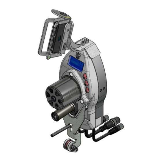
Technical Data and Installation Configuration of SM-DIN/DUOLOOP/ETH and SM-DIN/DUOLOOP/PFN Boards For the configuration of SM-DIN/DUOLOOP/ETH and SM-DIN/DUOLOOP/PFN Boards, please refer to the relevant manual. DIAPERFEEDER IP54 overall dimensions (in mm) DIAPERFEEDER IP54 - 2.13 -... - Page 24 Technical Data and Installation DIAPERFEEDER IP54 Unit TS44/1000RW/IP Coil separator Coil separator adjustment screws (see chapt. 4) Device fastening screws (No. 2) TS44/1000rw Tension Sensor CABLE LENGTH=50cm POWER CONNECTOR Fastening hole with M4 x 20 screw Loading cell (tension sensor) Note: the TS44..
-
Page 25: Instructions For Correct Yarn Threading
Technical Data and Installation Instructions for Correct Yarn Threading Thread the yarn inside the lower buckle , then make one coil around the roller , passing beneath the separation element , as shown on the figure above. Set the yarn over the loading cell of TS44 sensor and thread it out of the upper buckle For correct separation of yarn coils on the coil separation element , slightly tilt the separation... - Page 26 Technical Data and Installation Page intentionally left blank - 2.16 - DIAPERFEEDER IP54...
-
Page 27: Chapter 3 - Operation
Operation 3 – OPERATION Operating Characteristics of DIAPERFEEDER IP54 Devices For programming and control of DIAPERFEEDER IP54 devices, 3 push-buttons, with green/red built-in LEDS and a LCD display are available to the operator. 1. E PUSH BUTTON (ENTER) Press and hold down this push-button to gain access to the advanced device programmable functions. -
Page 28: Symbols Shown On Lcd
Operation 3. + PUSH BUTTON (CONTROL) Press this push-button to temporarily de-activate the device (lighting of front/rear LEDs and of ENTER, RESET, CONTROL push-button LEDs); press it again to reactivate the device. This button also allows de-activating (OFF) the power unit. During the programming phase, press it to increase the value of displayed parameter. -
Page 29: Functions Directly Available To The Textile Machine Operator
Operation C – Value Visualization Area It shows the yarn tension value, during the normal operation, or the parameter being programmed. D – Graphic Visualization Area It shows, in graphical form (through a logarithmic scale) both average and peak tension values. Functions Directly Available to the Machine Operator The operator of a machine equipped with DIAPERFEEDER IP54 devices has the possibility of carrying out some simple manual operations on the device themselves,... -
Page 30: Exclusion And Re-Inclusion Of A Diaperfeeder Ip54 Device
Operation 3) Exclusion and Re-inclusion of a DIAPERFEEDER IP54 Device When needed, it is possible to temporarily exclude a DIAPERFEEDER IP54 device, in order to avoid undesired starts due to vibrations, etc. To exclude and re- include a device, operate as follows: Exclusion: Press and hold down for 3 seconds The display will show the exclusion confirmation request. -
Page 31: Programming The Diaperfeeder Ip54Devices
Operation Programming the DIAPERFEEDER IP54Devices The DIAPERFEEDER IP54device offers two programming environments: (allows programming exclusively the device main tension) SIMPLE (allows programming all the device parameters) ADVANCED To get access to the programming environment, press and hold down for 3 seconds the ENTER button, while the device is operating in Control environment. -
Page 32: Advanced Programming Of Diaperfeeder Ip54 Devices
STOP (NO or NC contact). The setting of these parameters is already done by BTSR during the device manufacturing (default values), however it can be easily changed by the machine operator, to meet specific requirements, using the advanced programming features. - Page 33 Operation Within the P3 level the following parameters can be programmed: OFFSET AUTO MOTOR CALIBRATION ACCESS CODE DEVICE IDENTIFICATION CODE Within the P4 level the following parameter can be programmed: MOTOR ROTATION DIRECTION SENSOR TYPE BAUDRATE APPLICATION DIAPERS YARN TYPE ALL YARN OR ELASTIC LANGUAGE SELECTION USE OF INTELLIGENT TENSION CONTROL ACCESSORY...
-
Page 34: General Diagram Of P1÷P4 Advanced Programming Levels And Default Settings
Operation General Diagram of P1÷P4 Advanced Programming Levels and Default Settings NOTES: The values shown refer to the default parameters (set by BTSR). LFA = Length of Absorbed Yarn in m/min The selectable languages are Italian, English, French, Spanish, German, Japanese. -
Page 35: P1 Programming Level
Operation P1 Programming Level LFA m/min ADVANCED MENU P1 The P1 programming level allows you to setup 3 parameters: Device main tension; Tolerance with respect to the main tension; Max deviation time from tolerance band; With the DIAPERFEEDER IP54in status, (LFA nnnn displayed on LCD) CONTROL press and hold it down for 3 seconds. - Page 36 Operation Example 1: Main Tension: 20 g Error Tension: ± 5 g Example 2: Main Tension: 50 g Error Tension: ± 20 g Example 3: Main Tension: 5.0 g Error Tension: ± 6 g - 3-10 - DIAPERFEEDER IP54...
- Page 37 Operation TIME ALARM P1.3 Time during which the tension value may exit from the tolerance band set by the previous parameter ( ). You can disable (OFF) this feature by ERROR TENSION holding the Enter button pressed for 3 seconds. [Allowed values 0.0 ÷...
-
Page 38: P2 Programming Level
Operation P2 Programming Level LFA m/min ADVANCED MENU P2 The P2 programming level allows you to setup 4 parameters: Device tension with machine stationary; Control of change-over speed from a given working tension to a higher tension ( RAMP UP Control of change-over speed from a given working tension to a lower tension ( RAMP DOWN... - Page 39 Operation Example 1: Final tension = 10 g Initial tension = 4 g N = 5 Example 2: Final tension = 10 g Initial tension = 4 g N = 20 Example 3: Final tension = 10 g Initial tension = 4 g N = 100 RAMP DOWN P2.3...
- Page 40 Operation Example 3: Final tension = 4 g Initial tension = 10 g N = 100 Choose the desired value using: (to increase the value) or (to decrease the value). to confirm. K-PID P2.4 This parameter represents a multiplier that affects the control algorithm depending on the yarn elasticity characteristics.
-
Page 41: P3 Programming Level
Operation P3 Programming Level LFA m/min ADVANCED MENU P3 The P3 programming level allows you to setup 4 functionality: Offset reading/execution and Auto Offset enabling; Device operation mode; Access code to programmable function; DIAPERFEEDER IP54identification code. to select the P3 level. to continue. - Page 42 Operation MOTOR CALIBRATION P3.2 Automatic function reserved to BTSR service staff, in case of motor replacement. It allows executing the automatic calibration of the new motor. To activate the motor calibration procedure, press and hold down for 3 seconds. The OFF indication will be replaced by 000 and the motor will automatically carry out a number of movements to both directions, in order to adjust the calibration, then it will stop and the OFF indication will re-appear.
-
Page 43: P4 Programming Level
Operation P4 Programming Level LFA m/min ADVANCED MENU P4 The P4 programming level allows you to select the various device operating modes: Yarn feeding motor rotation direction (clockwise or counter clockwise); Size in grams of TS44.. tension sensor used (either 100 g. or 1,000 g.); Communication baud rate over the serial interface;... - Page 44 Operation BAUDRATE P4.3 This parameter allows you to setup the communication speed on the DIAPERFEEDER IP54serial interface. [Allowed values: 57600 or 115200] to choose the desired speed. to confirm the speed shown on display and move to the next parameter. APPLICATION SELECTION P4.4 This function allows you to choose one of the pre-defined applications.
- Page 45 Operation UNICO P4.8 This function allows you to set up the automatic detection feature of a possible intelligent accessory connected to the DIAPERFEEDER IP54 device. The detection condition is indicated by the lighting of label P4. for 3 seconds to toggle between AUTO to confirm and return to P4 menu.
- Page 46 Operation Page intentionally left blank - 3-20 - DIAPERFEEDER IP54...
-
Page 47: Indications Provided By The Red Leds On Diaperfeeder Ip54 Device
Troubleshooting and Maintenance 04 – DIAPERFEEDER IP54 Troubleshooting and Maintenance Indications Provided by the Red LEDs on DIAPERFEEDER IP54 Device Status of DIAPERFEEDER IP54 device Led on the TS44.. sensor Identification BLINKING GREEN/RED ALTERNATE FLASHING ERROR E2 BLINKING GREEN/RED ALTERNATE FLASHING MOTOR LOCKED (with CONTROL button)(*) -
Page 48: Troubleshooting Table
2) Turn the electrical supply of device OFF and internal protections then ON again If you cannot locate the cause of failure, please contact your BTSR reseller (it could be necessary to send the device to the BTSR repair centre). E3 displayed on 1) Presence of yarn residuals 1) Clean the loading cell of TS44.. - Page 49 DIAPERFEEDER IP54 STOP output press the "Control " button and confirm the lighting of red LEDs; if this does not occur please contact your BTSR reseller (it could be necessary to send the device to the BTSR repair centre). The DIAPERFEEDER...
- Page 50 Troubleshooting and Maintenance If the fault is not included in the above table, please contact your local BTSR reseller, giving a detailed description of the kind of fault and the conditions in which it occurred. Should be necessary to call the BTSR Technical Service Department, read the code printed on the faulty device, as this information could be useful to BTSR technicians.
-
Page 51: Errors Detected On The Sm-Din/Duoloop Boards
Troubleshooting and Maintenance Errors detected on the SM-DIN/DUOLOOP boards RAM check error inside the Board EEPROM check error inside the Board Communication error with a TS55 device (*) Communication error with a DIAPERFEEDER device (*) General alarm on a DIAPERFEEDER device (*) Entangled yarn alarm on a DIAPERFEEDER device (*). -
Page 52: Errors Detected On The Board Sm-Din/Duoloop/Eth And Sm-Din/Duoloop/Pfn
Troubleshooting and Maintenance Errors detected on the Board SM-DIN/DUOLOOP/ETH and SM-DIN/DUOLOOP/PFN Communication error. Error on a Diaper Feeder device. Diaper Feeder device locked (the button on the device has been pressed). Door open. Spool-holder carriage not correctly inserted. Left spool exhausted (Matrix Cube 2). Right spool exhausted (Matrix Cube 2). - Page 53 Troubleshooting and Maintenance TS55 sensor and Diaper Feeder device identification in progress. This message appears when the identification is executed from PC or Smart Matrix terminal. Diaper Feeder device identification in progress. This message appears when the identification is executed from PC or Smart Matrix terminal.
-
Page 54: Calibration Of Tension Sensors
Repair Any repair activity on electronic devices the System (DIAPERFEEDER IP54 Devices, TS44.. TS55.. and IS3F.. sensors) must be carried out by specialized BTSR Service Staff. Any repair attempt carried out by non-authorized personnel will invalidate the warranty terms. - 4-8 -... -
Page 55: Coil Separator Adjustment
Troubleshooting and Maintenance Coil separator adjustment − For yarn coil separator adjustment operate on the screws indicated below Yarn coil separator adjustment screws Even if the torque of motor driving the roller rotation is very low and does not involve hazards for the operator safety, it’s always advisable to lock the motor prior to operate on the devices (yarn threading, tilt adjustment of coil separation element, etc.) in order to avoid unexpected motor startup events. -
Page 56: Periodic Cleaning Of The Components
Troubleshooting and Maintenance Periodic Cleaning of the Components This operation must by carried out at least twice a year, or more frequently, when the system operates under critical environmental conditions. To this purpose it is advisable to carry out a monthly visual inspection to establish the most appropriate frequence of such cleaning works. - Page 57 DISTRIBUTOR BTSR International S.p.A. Via S. Rita 21057 OLGIATE OLONA (VA) Phone 0331-323202 Fax 0331-323282 Internet: www/btsr.com REV. 1.4 – 02/16...
Need help?
Do you have a question about the DIAPERFEEDER IP54 DUOLOOP and is the answer not in the manual?
Questions and answers