Table of Contents
Advertisement
Advertisement
Table of Contents

Subscribe to Our Youtube Channel
Related Manuals for btsr SMART MATRIX WARP


Summary of Contents for btsr SMART MATRIX WARP
- Page 1 SMART MATRIX WARP Operating Manual ENGLISH Rev. 3.0 - December 2011...
- Page 2 SMART MATRIX WARP - Rev. 3.0 - December 2011 Copyright - BTSR – All rights reserved. This manual is entrusted to the users of SMART MATRIX WARP system developed for control/monitoring activities of textile machinery equipped with either quality control (IS3) or tension control (TS5/TS7) sensors.
- Page 3 Introduction...
- Page 5 IS3/TS5/TS7 sensors; in addition, it provides a real time monitoring of sensors behavior and production efficiency. Manual Objectives This manual has been written to provide the users of SMART MATRIX WARP system with the essential information required to: •...
- Page 6 Section 2 – provides the operating instructions for a correct use of the SMART MATRIX WARP terminal as well as the parameter configuration/programming instructions and data/errors display facilities.
-
Page 7: Table Of Contents
Sensors (ACT/Ds) Interface ......................... 1-6 SM-DIN ↔ ACT/Ds ↔ Machine Interface ....................1-7 SMART MATRIX ↔ SM-DIN/PC/DISPLAY Interface .................. 1-8 SMART MATRIX WARP Generic Application Diagram (IS3)............... 1-9 SMART MATRIX WARP Generic Application Diagram (TS5)..............1-10 2 – Operating Instructions SMART MATRIX WARP Operation...................... - Page 8 Table of Contents 3 – System Components and Configuration IS3 Sensor Features............................. 3-1 TS5/TS7 Sensor Features..........................3-4 Differences between TS5 and TS7 Sensors ....................3-13 SM-DIN WARP ............................. 3-14 ID and Transmission Speed Configuration on Each SM-DIN Board............3-15 Machine Configuration (Levels, Creels, Rows, Columns, Bar) ..............3-16 SLOW-FAST Control Parameters ........................
-
Page 9: Connections And Electrical Interface
Connections and Electrical Interface... -
Page 11: Pc ↔ Smart Matrix ↔ Sm-Din Connection
↔ ↔ SMART MATRIX SM-DIN Connection PC ↔ SMART MATRIX ↔ SM-DIN Connection The following diagram shows the interconnections among: SMART MATRIX Terminal, SM-DIN Sensor Interface Boards and PC. The PC is mainly used for firmware update operations on SMART MATRIX Terminal, SM-DIN Boards and Sensors (**). -
Page 12: Smart Matrix ↔ Sm-Din ↔ Is3 + Act/D Connection
↔ SM-DIN ↔ IS3 + ACT/D Connection SMART MATRIX SMART MATRIX ↔ SM-DIN ↔ IS3 + ACT/D Connection The following diagram shows the connection of IS3 Sensors and Lamp Interface Modules (ACT/D) to SM- DIN Boards, as well as the connection between SM-DIN Boards and SMART MATRIX. MAX 100 BOARDS SM-DIN... -
Page 13: Smart Matrix ↔ Sm-Din ↔ Ts5 + Act/D Connection
↔ SM-DIN ↔ TS5 + ACT/D Connection SMART MATRIX SMART MATRIX ↔ SM-DIN ↔ TS5 + ACT/D Connection The following diagram shows the connection of TS5 Sensors and Lamp Interface Modules (ACT/D) to SM- DIN Boards, as well as the connection between SM-DIN Boards and SMART MATRIX. MAX 100 BOARDS SM-DIN... -
Page 14: Smart Matrix ↔ Sm-Din ↔ Ts7 + Act/D Connection
↔ SM-DIN ↔ TS7 + ACT/D Connection SMART MATRIX SM-DIN ↔ SMART MATRIX ↔ TS7 + ACT/D Connection The following diagram shows the connection of TS7 Sensors and Lamp Interface Modules (ACT/D) to SM- DIN Boards, as well as the connection between SM-DIN Boards and SMART MATRIX. MAX 100 BOARDS SM-DIN... -
Page 15: Sm-Din ↔ Machine Interface
↔ SM-DIN Machine Interface SM-DIN ↔ Machine Interface The following diagram shows the electrical interface (pin assignment) of SM-DIN Warp Board. The sensor interface is shown on the following page. Machine Interface (INPUT) Power Supply (*) Machine Interface (OUTPUT) Recommended power supply: 24 Vdc. If the ATC POWER unit is used, the power supply on PINs 1 and 2 of Power connector must not be provided, because the entire system is already supplied (through the ATC POWER module itself) by the PSU 10ASM unit (please refer to diagrams on pages 1-9 and 1-10). -
Page 16: Sensors (Act/Ds) Interface
Sensors (ACT/Ds) Interface Sensors (ACT/Ds) Interface The following diagram shows the electrical interface (pin assignment) of SM-DIN to sensors connection. As you may note, 4 identical connectors are available, allowing you to connect up to 4 sensors and/or ACT/Ds chains. SM-DIN nn Module –... -
Page 17: Sm-Din ↔ Act/Ds ↔ Machine Interface
↔ ↔ SM-DIN ACT/Ds Machine Interface SM-DIN ↔ ACT/Ds ↔ Machine Interface The following diagram shows the electrical interface (pin assignment) of ACT/D modules. - Lamp/Cutter, etc. - - Lamp/Cutter, etc. - Numbering button Lv = Green Led (normally flashing) Lr = Red Led (on = communication with SM-DIN in progress) Lr1 =... -
Page 18: Smart Matrix ↔ Sm-Din/Pc/Display Interface
↔ SMART MATRIX SM-DIN/PC Interface SMART MATRIX ↔ SM-DIN/PC/DISPLAY Interface The following figure shows the electrical interface (pin assignment) of Smart Matrix terminal. (**) Supply voltage from SM-DIN Supply voltage from SM-DIN (*) Press the P button to setup the communication speed on CV232/485/9: - LED LV with single flashing = 57.6 Kbps - LED LV with double flashing... -
Page 19: Smart Matrix Warp Generic Application Diagram (Is3)
SMART MATRIX WARP Generic Application Diagram (IS3) SMART MATRIX WARP Generic Application Diagram (IS3) On the example shown, the power supply of the entire system is provided by the PSU 10 ASM power supplier, by means of the ATC POWER unit, whereby it does not have to be provided on PINs 1 and 2 of SM-DIN WARP unit Power connector. -
Page 20: Smart Matrix Warp Generic Application Diagram (Ts5)
SMART MATRIX WARP Generic Application Diagram (TS5) SMART MATRIX WARP Generic Application Diagram (TS5) On the example shown, the power supply of the entire system is provided by the PSU 10 ASM power supplier, by means of the ATC POWER unit, whereby it does not have to be provided on PINs 1 and 2 of SM-DIN WARP unit Power connector. -
Page 21: Operating Instructions
Operating Instructions... -
Page 23: Smart Matrix Warp Operation
SMART MATRIX WARP Operation All the Configuration, Parameter Setting, Data & Error Display operations, etc. can be managed by the Operator in quick and intuitive way, using the SMART MATRIX WARP control terminal. The SMART MATRIX ↔ Operator interface consists of: A - Graphic display showing: •... -
Page 24: Navigation Throughout The Display Windows
SMART MATRIX WARP Operation Navigation throughout the Display Windows Many configuration/parameter setting functions of SMART MATRIX system require a number of parameters distributed among multiple display windows. All the “Window Selection”, “Parameter Selection within a Window” and “Parameter Setting” functions on SMART MATRIX terminal, can be carried out using exclusively the multi-function Rotary Selector, through a navigation technique based upon “Pointing”, “Selecting”... - Page 25 SMART MATRIX WARP Operation 1 – Navigation inside the Selected Window (TENS) Turn the selector to “Point” in sequence the various items of the window → → → TH%). (TENS WORK TENSION The frame indicates the “Pointed” field. Click to “Select” the pointed item. The field name will be shown in reverse and the symbols: appear to the right of the field value.
- Page 26 1 – Navigation inside the Selected Window (TENS) Entering Alphanumeric Values Some functions of SMART MATRIX WARP terminal require typing alphanumeric data fields (e.g. Style Name setup or change). To make this operation easier, a soft keyboard has been implemented, which allows entering capital/small letters, numbers and graphic symbols.
- Page 27 SMART MATRIX WARP Operation It allows clearing the character to the left of cursor DEFAULT STYLE NAME It allows moving the cursor one position to the left. It allows moving the cursor one position to the right. It allows leaving the string entering function.
- Page 28 SMART MATRIX WARP Operation 3 – Parameters Saving Once you have setup all the desired parameters, press and hold down 3 seconds the rotary selector. SAVE to save the settings BACK to return to previous screen without saving EXIT to return to menu without saving...
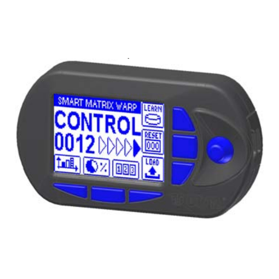
- Page 29 SMART MATRIX WARP Operation Immediate Function Activation through the SMART MATRIX Buttons The 6 blue buttons (B1 ~ B6) allow you to directly activate some system functions without passing through the menu items. Such functions are indicated by the icons associated with the buttons, as shown on the following figure.
- Page 30 SMART MATRIX WARP Operation Interpretation of Operating Screens • System working in Control status • No errors detected! • 0012 = 12 active sensors • Tension Low error (TENS L) on CREEL B • Coordinates of sensor that detected the error:...
-
Page 31: Smart Matrix Warp Menu Structure
SMART MATRIX WARP Menu Structure SMART MATRIX WARP Menu Structure Alternating Error Error details Main Menu Style Configuration Style Loading System Configuration In the description of the various functions, the following graphic symbols will be used: Select the desired option and click to confirm. -
Page 32: Choice Of Device Type (Is3 Or Ts5/Ts7)
This function allows you to choose the type of devices used in your application: either Yarn Running Sensors (IS3F) or Tension Sensors (TS5/TS7). No mixed configurations are allowed! Some parameters and menu items shown on the SMART MATRIX WARP screens will depend on the choice made with this function. Enter the SETUP menu. -
Page 33: Creel Mapping (Std Or Adv)
Creel Mapping (STD or ADV) Creel Mapping (STD or ADV) SETUP → This function allows you to choose the creel configuration type. 2 configuration modes are available: STANDARD and ADVANCED. STANDARD Mode: each creel can be configured only as a “regular” matrix of rows/columns (e.g. square/rectangular creel). -
Page 34: Sensor Configuration And Numbering
Sensor Configuration and Numbering Sensor Configuration and Numbering SETUP → IDENTIFY This function allows you to univocally identify each IS3/TS5/TS7 device connected to SM-DIN WARP Boards; moreover it allows to define the creel structure (level number, priority, etc.) Enter the SETUP menu. - Page 35 Sensor Configuration and Numbering Example with CREEL LEVELS parameter = OFF (1 creel level) • Point and select CREEL LEVELS. • Set the number of CREEL LEVELS [in this case CREEL LEVELS = OFF]. • Point and select CREELS NUMBER •...
- Page 36 Sensor Configuration and Numbering To return to CONTROL status. Example with CREEL LEVELS parameter = 02 (2 creel levels) • Point and select CREEL LEVELS. • Set the number of CREEL LEVELS [Allowed values 02 ÷ 04; on this example CREEL LEVELS = 02].
- Page 37 Sensor Configuration and Numbering • The example shown indicates that the numbering (identification) procedure of the 8 sensors belonging to creel 1A is going to start. The flashing small square indicates the sensor located on “Column 1 - Row 1 - Creel 1A”.
- Page 38 Sensor Configuration and Numbering Single Sensor Numbering To number a single sensor (for instance in case of sensor replacement) operate as follows: • Carry out all the operations described for sensor configuration and numbering until the sensor map appears. • Select the coordinates (Creel, Column, Row of the sensor to be re-numbered, e.g.
-
Page 39: Lamps (Act/D) Configuration And Numbering
Lamps (ACT/D) Configuration and Numbering Lamps (ACT/D) Configuration and Numbering → SETUP LAMP CONFIG This function allows you to identify the ACT/D modules used to drive the lamps that signal the error conditions on the machine. You may assign a lamp to each Row, Column or Bar (according to the priority defined with the IDENTIFY function), with the possibility to add a lamp for each Creel. - Page 40 Lamps (ACT/D) Configuration and Numbering • Select the field indicating the number of ACT/D modules connected to Board 1. • Set the number of ACT/D modules actually connected to Board 1 (e.g. 2) and confirm. Note: If you use the lamps both on Column and on Creels, this number must be the sum of all ACT/D modules (Columns + Creels).
- Page 41 Lamps (ACT/D) Configuration and Numbering Configure the outputs of ACT/D modules (OUT1, OUT2, OUT3). Activation delay DELAY TIME – (ms) Duration of activation pulse PULSE TIME – (ms) Frequency of output activation BLINK TIME – (ms) The outputs of ACT/D modules can be programmed either as continuous signals (setting PULSE TIME BLINK TIME...
-
Page 42: Smart Matrix Code
Smart Matrix Code Smart Matrix Code → SETUP MATRIX CODE This function allows you to assign an identification code to the SMART MATRIX terminal, in case of application that uses multiple terminals. Enter the SETUP menu. Select MATRIX CODE. Choose the SMART MATRIX identification code and activate the save function. -
Page 43: Board Mode
Board Mode Board Mode → SETUP BOARD MODE This function allows you to set the STOP output activation modes by the Board: STANDARD mode: if an error occurs, the system generates the alarm and stops the process until the fault is corrected. -
Page 44: Options
Options Options → SETUP OPTIONS This function allows you to choose the desired operation modes for sensor numbering and for style parameter settings. Enter the SETUP menu. Select OPTIONS. DEVICE ID MODE NORMAL PROGRESSIVE STYLE EDITOR MODE FAST/SLOW SINGLE (see the comment below) To confirm the settings. -
Page 45: Input/Output Configuration On Sm-Din/Smart Matrix
Input/Output Configuration on SM-DIN/Smart Matrix Input/Output Configuration on SM-DIN/Smart Matrix → SETUP I/O CONFIG This function allows you to configure the input/output signals of all the SM-DIN Boards (BOARDS option) as normally open (NO) or normally closed (NC) contacts. It also allows you to configure the output relay of SMART MATRIX terminal as normally open (NO) or normally closed (NC) contact. - Page 46 Input/Output Configuration on SM-DIN/Smart Matrix Configure the output relay of SMART MATRIX terminal as or NC. To activate the save function. SAVE to save the choice, BACK to return to the previous screen without saving, EXIT to return to menu. SMART MATRIX - 2-24 -...
-
Page 47: Efficiency Calculation Mode
Efficiency Calculation Mode Efficiency Calculation Mode → SETUP EFFICIENCY This function allows you to choose whether the POWER-DOWN TIMES shall be included or excluded in the calculation of efficiency index that will be shown pressing the button. Enter the SETUP menu. -
Page 48: Keycode Setting
Keycode Setting Keycode Setting → SETUP KEY CODE This function allows you to configure the user names and access passwords (KEY CODE) to the menus and other options of SMART MATRIX system. The first user ADMIN (Administrator) is set by default and cannot be deleted. The ADMIN user has the access rights to all menus and system options. - Page 49 Keycode Setting Clear a User Press the indicated button to remove the selected user from the list. Change Configuration Press the indicated button to edit (change) the access rights of selected user. Change the configuration of menus and options available to the selected user (SETUP MENU,...
-
Page 50: Communication Test
Communication Test Communication Test SETUP → TEST COM This function allows you to check: The efficiency level of communications between SMART MATRIX and SM-DIN Boards and between SM- DIN Boards and Sensors. The correct operation of Sensors. The correct operation of ACT/D modules →... -
Page 51: Sensors Test
Sensors Test Sensors Test SETUP → TEST COM → TS5/D (IS3) TEST Enter the SETUP menu. Select TEST COM. Select TS5/D (IS3) TEST. Select the desired creel and sensor. Coordinates of selected sensor (the red led shall flash on selected sensor). To select the sensor coordinates (Creel, Column and Row) you may use the “shortcut”... -
Page 52: Lamps Test
Lamps Test Lamps Test SETUP → TEST COM → COL (ROW) (BAR) LAMP Enter the SETUP menu. Select TEST COM. Select COL (ROW) (BAR) LAMP CREEL LAMP to carry out the test. The display will show the lamps map. Select the desired Creel and lamp. The red led shall flash on the selected ACT/D module. -
Page 53: Offset Ts5/Ts7
Offset TS5/TS7 Offset TS5/TS7 SETUP → SERVICE → TS5 OFFSET This function, available for TS5/TS7 sensors only, allows you to carry out the calibration (offset), either on all sensors or on the specified sensor. Prior to start the calibration, remove the yarn from the loading cell of the involved sensors. Enter the SETUP menu. - Page 54 Offset TS5/TS7 OFFSET to carry out the calibration. to confirm the operation. OFFSET operation completed. To select the sensor coordinates (Creel, Column and Row) you may use the lower “shortcut” buttons or press in sequence the rotary selector. Shortcut Buttons available to Speed-up the Selection It selects all sensors of selected Creel/Column/Row.
-
Page 55: Sensors Firmware Upgrade
Sensors Firmware Upgrade Sensors Firmware Upgrade SETUP → SERVICE → XXX UPG This function allows you to upgrade the firmware of TS5/TS7 or IS3F sensors. The TS5/TS7 or IS3F indication depends on the type of device chosen with the IDENTIFY function. - Page 56 Sensors Firmware Upgrade to confirm the operation. To select the sensor coordinates (Creel, Column and Row) you may use the lower “shortcut” buttons or press in sequence the rotary selector. Shortcut Buttons available to Speed-up the Selection It selects all sensors of selected Creel/Column/Row. It toggles the sensors selection status within the selected Creel/Column/Row.
-
Page 57: Act/D Upgrade
ACT/D Upgrade ACT/D Upgrade SETUP → SERVICE → ACT/D UPG This function allows you to upgrade the firmware of ACT/D modules. The upgrading requires two separate steps for lamps associated with columns/rows/bars and for lamps associated with creels. Enter the SETUP menu. - Page 58 ACT/D Upgrade To continue. UPGRADE to carry out the upgrading. to confirm the operation. Repeat the same sequence of operations to update the firmware of lamps associated with the creels (CREEL LAMP). You may use the same shortcut buttons described for sensors firmware upgrade. SMART MATRIX - 2-36 -...
-
Page 59: Matrix Lcd Adjustment
MATRIX LCD Adjustment MATRIX LCD Adjustment SETUP → LCD DISPLAY This function allows you to adjust the brightness and contrast of display and to set the display auto-off time (1 .. 20 minutes, or No Off if the auto-off function is not required). Enter the SETUP menu. -
Page 60: Led Display Setup
LED Display setup LED Display setup SETUP → LED DISPLAY This function allows you to set the Customer name that will appear as a sliding text on the external display. Besides the name set with this function, the display will visualize in sequence a series of information about the system status: Number of working yarns Process efficiency... -
Page 61: Information About Smart Matrix Warp
Information about SMART MATRIX WARP SETUP → INFO This function allows you to detect the Hardware, Firmware, OS and Boot Program versions. These values shall be communicated to BTSR Service Department when requiring technical support to solve specific problems. Enter the SETUP menu. -
Page 62: Style Parameters Programming (Ts5/Ts7)
Style Parameters Programming (TS5/TS7) Style Parameters Programming (TS5/TS7) STYLE This function allows you to program the detection parameters of TS5/TS7 sensors. For detailed information about the individual parameters, please refer to Section 3: System Components and Configuration - TS5/TS7 Sensors. Select the STYLE EDIT menu item. - Page 63 Style Parameters Programming (TS5/TS7) BACK to return to the previous screen, EXIT to return to the SLOW MODE SETUP FAST MODE SETUP selection screen. Repeat the same procedure to setup the FAST FAST MODE SETUP parameters ( To save the settings. SAVE to save and set the style name BACK...
-
Page 64: Style Parameters Programming (Is3F)
Style Parameters Programming (IS3F) Style Parameters Programming (IS3F) STYLE This function allows you to program the detection parameters of IS3 sensors. For detailed information about the individual parameters, please refer to Section 3: System Components and Configuration – IS3 Sensors. Select the STYLE EDIT menu item. - Page 65 Style Parameters Programming (IS3F) BACK to return to the previous screen, EXIT to return to the SLOW MODE SETUP FAST MODE SETUP selection screen. Repeat the same procedure to setup the FAST FAST MODE SETUP parameters ( To save the settings. SAVE to save and set the style name BACK...
-
Page 66: Style Loading
Style Loading Style Loading LOAD This function allows you to select the desired style from the database and load it to the IS3F or TS5/TS7 sensors. The same function may also be activated pressing the button Select the LOAD menu item. To load the desired style. -
Page 67: Sensors Histogram
Sensors Histogram Sensors Histogram This function, which can be activated pressing the button , provides two different indications depending on the type of sensors (IS3F or TS5/TS7) selected with the IDENTIFY function. In case of TS5/TS7 sensors it indicates the tension value detected in real-time by the various sensors. In case of IS3 sensors it provides a quality index of sensor reading (depending on sensor position/yarn typology)*. - Page 68 Sensors Histogram BACK to go back to previous screen EXIT to go back to the graphic display screen. To continue BACK to go back to previous screen EXIT to exit the function and go back to CONTROL status. To switch between “Creel selection” and “Column selection”, you may either use the “shortcut” buttons or press in sequence the rotary selector.
-
Page 69: Efficiency Data
Efficiency Data Efficiency Data This function allows you to display the production efficiency value (work time, stop time, total time and efficiency index %). The efficiency index calculation depends on the setting carried out with the EFFICIENCY function within the SETUP menu. -
Page 70: Error Counter Display (Ts5/Ts7)
Error Counter Display (TS5/TS7) Error Counter Display (TS5/TS7) This function allows you to display the error counters at creel level and at detailed level. Press the indicated button to directly access the counters. Select the desired creel. The indicated values represent the sum of all errors (TENS H, TENS L, PEAK H, PEAK L, NOYARN) referred to the... - Page 71 Error Counter Display (TS5/TS7) DETAILS to continue with the display of details BACK to return to previous screen MENU UP to return to the error display screen at creel level EXIT ALL to return to main menu Select the desired Row. To view the details of errors.
-
Page 72: Error Counter Display (Is3)
Error Counter Display (IS3) Error Counter Display (IS3) This function allows you to display the error counters at creel level and at detailed level. Press the indicated button to directly access the counters. Select the desired creel. The indicated values represent the sum of all errors (BROKE, UNCUT) referred to the selected creel. - Page 73 Error Counter Display (IS3) DETAILS to continue with the display of details BACK to return to previous screen MENU UP to return to the error display screen at creel level EXIT ALL to return to main menu Select the desired Row. To view the details of errors.
-
Page 74: Learn
LEARN LEARN The LEARN function (which can be activated pressing the button ) allows you to carry out a learning cycle during which the system detects and memorizes the number of sensors (nnnn) inside which the yarn is regularly running, excluding the sensors in alarm status. At the end of learning cycle, after the time interval defined in Delay Control, the system automatically activates the Control mode and continuously controls the regular running of yarn inside all the “nnnn”... -
Page 75: Smart Matrix Error Message
SMART MATRIX Error Message SMART MATRIX Error Message During the normal operation, the SMART MATRIX display will show CONTROL XXXX (where XXXX is the number of active sensors). In case of errors or detection failures, the CONTROL XXXX indication will be replaced by a message which summarizes the type of error or failure occurred. - Page 76 SMART MATRIX Error Message TS5 mode with “Bars” priority TENS H CREEL #A Tens error, H Creel #A Bar #B Sensor #C BAR #B SEN #C TENS L CREEL #A Tens error, L Creel #A Bar #B Sensor #C BAR #B SEN #C PEAK H CREEL #A...
- Page 77 SMART MATRIX Error Message Communication errors with ACT/D modules ERR ACT Communication error with ACT/D module, Creel #A Bar #B CREEL #A (For Bar lamps) BAR #B ERR ACT Communication error with ACT/D module, Creel #A (For Creel lamps) CREEL #A The BAR indication is replaced by ROW, if the IDENTIFY function was programmed with Row or Column “Priority”.
-
Page 78: Errors Shown On Display Of Sm-Din Boards
Errors shown on Display of SM-DIN Boards Errors shown on Display of SM-DIN Boards The failures/errors on SM-DIN modules are indicated by the following codes on the Board’s display: Generic Alarm. At least one sensor signaled an alarm. Error detected during the Learn phase RAM Error Error detected on RAM memory contents;... -
Page 79: System Components And Configuration
System Components and Configuration... -
Page 81: Is3 Sensor Features
IS3 Sensor Features IS3 Sensor Features The IS3 electronic sensors are capable of detecting, due to a patented and advanced control technology, the image variation of a moving yarn under control; it can show with absolute certainty the actual movement or stop condition of the yarn. - Page 82 IS3 Sensor Features Settings that Affect the IS3 Sensor Detection Features The IS3 series sensors are not simply detecting the presence of the yarn, but they are working as true micro- computers. They provide a digital signal output, which reflects the condition of the yarn within the detection area: Normal yarn running condition Yarn stopped or broken condition...
- Page 83 IS3 Sensor Features The suggested values for different yarns are as hereafter indicated: Very thick yarns Thick yarns Medium yarns Fine yarns (single filament yarn) 6 - 8 Very fine yarns (Lycra®) 9 - 10 Reaction time (DELAY) The DELAY parameter allows the adjustment of the sensor to the characteristics of the yarn to be worked (e.g.
-
Page 84: Ts5/Ts7 Sensor Features
TS5/TS7 Sensor Features TS5/TS7 Sensor Features The TS5/TS7 devices are intelligent sensors able to detect, due to sophisticated control technique, the tension applied to the yarn being controlled, signaling possible anomalies about the tension itself. The tension exerted by the yarn on sensor’s loading cell ((depending on the feeding tension of the yarn itself), is detected by the electronics of the sensor and converted by the built-in DSP (Digital Signal Processor) into a digital signal that can be interpreted both by the TS5/TS7 sensor and by the SMART MATRIX program. - Page 85 TS5/TS7 Sensor Features TS5/TS7 Sensor Types The TS5/TS7 sensors are available in various typologies to meet specific needs of individual installations/applications. The following diagram shows a detailed coding rule of the available sensors, depending on possible variables. TSX/D Example: TS5/D500DD = TS5 sensor, 500 grams weight, with model D eyelet, Diamond finishing Eyelet Models SMART MATRIX - 3-5 -...
- Page 86 TS5/TS7 Sensor Features Mechanical Characteristics of TS5/TS7 Sensors Sizes (mm) The cable with external connector identifies the TS5 version: for more details, please refer to the Differences between TS5 and TS7 Sensors paragraph. SMART MATRIX - 3-6 -...
- Page 87 TS5/TS7 Sensor Features Usage The cable with external connector identifies the TS5 version: for more details, please refer to the Differences between TS5 and TS7 Sensors paragraph. SMART MATRIX - 3-7 -...
- Page 88 TS5/TS7 Sensor Features Interpretation of the Signaling Lights Located on the Sensors Green Led ON Sensor under normal control; No defects detected by the sensor either in Control on Monitor mode. Green LED FLASHING Sensor under automatic numbering procedure. Sensor in Delay Control phase Sensor disabled Red LED FLASHING During the machine operation either in Control or Monitor mode the sensor detected a failure...
- Page 89 TS5/TS7 Sensor Features Parameters that Affect the TS5/TS7 Sensor Detection Features The TS5/TS7 series sensors are microprocessor based electronic sensors capable of detecting the most common types of yarn tension failures: Positive/negative threshold levels exceeded Positive/negative peak levels exceeded Missing Yarn The yarn running inside the sensor touches the loading cell that moves horizontally depending on the tension applied to the yarn itself.
- Page 90 TS5/TS7 Sensor Features This parameter indicates the Max Peak Value (expressed as positive percentage value) with respect to the reference tension WORK TENSION, above which a failure condition will be signaled. The following two values must be specified: PH % = Positive error percentage (max peak) with respect to the tension WORK TENSION PH (ms) = Minimum duration of error condition to signal the failure This parameter indicates the Min Peak Value (expressed as negative percentage value) with respect to the reference tension WORK TENSION, below which a failure condition will be signalled.
- Page 91 TS5/TS7 Sensor Features Other factors that may affect the control DELAY [s] Is the sensor waiting time before starting the control process, namely the time needed to the machine to reach the set speed (Programmable). TENS [ABS/REL] It defines the sensor operating mode as regards the calculation of min/max threshold and peak values with reference to the yarn tension ABS: mode –...
- Page 92 TS5/TS7 Sensor Features STOP [NO-NC] It defines the operating mode of the Stop output: STOP NO: The Stop output is normally open and it is connected to ground to signal an alarm condition. STOP NC: The Stop output is normally closed (connected to ground) and it is opened to signal an alarm condition.
-
Page 93: Differences Between Ts5 And Ts7 Sensors
The only difference being the electrical interface: Built-in cable with either 4 or 8 pin connector 2 built-in connectors for “daisy-chain” connection (like IS3F) The 8 pin connector is not used on SMART MATRIX WARP application. TS5 8 pin TS5 4 pin +VCC... -
Page 94: Sm-Din Warp
SM-DIN WARP SM-DIN WARP The SM-DIN WARP Boards represent the interface between Sensors/Lamps (ACT/D) and SMART MATRIX Terminal. For more details about the electrical interface, please refer to Section 1. On each SM-DIN WARP Board it is necessary to setup 2 essential parameters: P01 = Unique Board identification code (01 –... -
Page 95: Id And Transmission Speed Configuration On Each Sm-Din Board
ID and Baudrate SM-DIN Configuration ID and Transmission Speed Configuration on Each SM-DIN Board (P01 - P02 Parameters) SMART MATRIX - 3-15 -... -
Page 96: Machine Configuration (Levels, Creels, Rows, Columns, Bar)
Machine Configuration (Levels, Creels, Rows, Columns, Bar) Due to the high number of sensors normally used for SMART MATRIX WARP applications it has been necessary to introduce an identification method allowing the operator to easily locate the sensors in a Logical way, depending on machine configuration. - Page 97 Machine Configuration (Creels, Rows, Columns, Bar) Example 1: Machine with only 1 creel consisting of 40 sensors Sensor Array Example 2: Machine with 2 creels (A e B), each one consisting of 40 sensors Example 3: Machine with 4 creels (A, B, C, D), each one consisting of 40 sensors SMART MATRIX - 3-17 -...
- Page 98 Machine Configuration (Creels, Rows, Columns, Bar) Example 4: Machine with 3 levels and 4 creels per level, each one with 40 sensors. In this case the creels are identified as: 1A, 1B, 1C, 1D for the first level 2A, 2B, 2C, 2D for the second level 3A, 3B, 3C, 3D for the third level SMART MATRIX - 3-18 -...
- Page 99 Machine Configuration (Creels, Rows, Columns, Bar) Priority Example Each individual creel can be configured independently from each other, by defining a “Virtual Array” of Rows and Columns. A lamp (driven by an ACT/D module) can be associated with each Row or Column and/or with each Creel.
- Page 100 Machine Configuration (Creels, Rows, Columns, Bar) As an alternative to the Rows/Columns configuration, it is possible to group the sensors on Bars and to associate an ACT lamp with each Bar and/or to each Creel. In this case, it will be necessary to configure: Bars Priority.
-
Page 101: Slow-Fast Control Parameters
SLOW-FAST Control Parameters SLOW-FAST Control Parameters One of the main features of the SMART MATRIX system is the possibility of programming 2 different sets of control parameters (SLOW and FAST) and automatically switching from one set to the other depending on the status of two external input signals, provided by the textile machine (SLOW EXT and FAST EXT). - Page 102 SLOW-FAST Control Parameters Page left intentionally blank SMART MATRIX - 3-22 -...
- Page 103 DISTRIBUTOR BTSR International S.p.A. Via S. Rita 21057 OLGIATE OLONA (VA) Tel. 0331-323202 Fax 0331-323282 Internet: www.btsr.com REV. 3.0 – 12/11...
Need help?
Do you have a question about the SMART MATRIX WARP and is the answer not in the manual?
Questions and answers
Hello good day, my name is Sezer. I **** the owner of SezerDuino software and informatics company. I would like to ask you a question about a module you developed. You have BTSR smart Matrix warp V08.0S02.0 module. With this module I can get images from dotmatrix. Can you help me with getting a second image (same image) and transferring it to the back of the machine? I **** waiting for your answer. Thanks in advance.