Table of Contents
Advertisement
Advertisement
Table of Contents
Troubleshooting

Subscribe to Our Youtube Channel
Related Manuals for btsr ULTRAFEEDER


Summary of Contents for btsr ULTRAFEEDER
- Page 1 ULTRAFEEDER YARN CONTROL SYSTEM Operating Manual ENGLISH Rev. 4.1 – February 2017...
- Page 2 ULTRAFEEDER – Rev. 4.1 – February 2017 Copyright - BTSR – All rights reserved. This manual is intended for the users of ULTRAFEEDER yarn feeding devices. It is suggested to carefully read the instruction reported in this manual before making the connections and use the system.
-
Page 3: Table Of Contents
Advantages obtained by using the SMART MATRIX FEEDER Terminal combined with ULTRAFEEDER Devices ..................................1.4 Further Advantages obtained by using a PC or Notebook Connected to the ULTRAFEEDER Device via Serial Line .................................. 1.4 Chapter 2 – TECHNICAL DATA AND INSTALLATION Technical Features .............................. - Page 4 Chapter 4 – ULTRAFEEDER TROUBLESHOOTING AND MAINTENANCE Indications Provided by the Red LEDs on ULTRAFEEDER Device ..............4.1 Troubleshooting on ULTRAFEEDER Devices ....................... 4.2 Useful Hints when using the ULTRAFEEDER device on socks or pantyhose production machines ....4.4 Ordinary Maintenance .............................. 4.5 Repairs..................................4.5 Chapter 5 –YTT DEVICE...
-
Page 5: Introduction
INTRODUCTION Congratulations for choosing a BTSR product. With our ULTRAFEEDER yarn feeding devices, with or without the SMART MATRIX FEEDER control unit or PFU/ 64 FS and SMART MATRIX PFU integrated system , you got an innovative, unique solution able to offer you multiple advantages concerning quality of your production. -
Page 6: How To Use This Manual
KTF/PW4 or PFU/64S power supply. Chapter 3 – Operation gives a detailed description of the necessary operations to setup and program the ULTRAFEEDER devices according to the application needs. Chapter 4 – Troubleshooting and Maintenance provides a quick guide to solving the main failures of ULTRAFEEDER devices. - Page 7 • EN 61326-1:2012 The person authorized to collect the Technical File is: Ing. M. Tomazzolli - info@btsr.com The above indications are purely for information purposes and should not be considered as an alias of the actual conformity statement subscribed and released by the Manufacturer.
- Page 8 70 db (A) SAFETY AND RELIABILITY OF CONTROL SYSTEMS Within the ULTRAFEEDER device, the only safety control system (motor locking prior to carry out the threading operation) has been implemented according to the principles of the Harmonized Norm EN ISO 13849-1:2015.
-
Page 9: Chapter 1 - Overview
Introduction of this manual. The ULTRAFEEDER devices can be used in a Master/Slave configuration, both as indicated on page 2.23 and in combination with other BTSR devices (Rolling FEEDER / Rolling MED). Moreover, using a Personal Computer or Notebook with the aid of PC-LINK KTF... - Page 10 (i.e. the time needed to complete the data transfer). Easy to install and manage The ULTRAFEEDER is a space saving device (159 x 63 x 76 mm). This permits you to install several devices on the same machine with limited encumbrances. The device has been designed bearing in mind not only the technological aspects, but also the ergonomic ones.
-
Page 11: Advantages Obtained By Using The Ultrafeeder Devices
Full control of yarn presence, even during the “LEARN” phase performed with the SMART MATRIX FEEDER/PFU control terminal (“reverse" applications). Possibility to find the best application conditions of ULTRAFEEDER device: (No of coils to be wound around the roller, ideal programming values for parameters etc), thanks to the continuous visualization, in graphic form, of both average and peak values of yarn tension. -
Page 12: Advantages Obtained By Using The Smart Matrix Feeder Terminal Combined With Ultrafeeder Devices
CONTROL LEARN available (BTSR Patent). With this function you can learn the amount of yarn fed during a sample cycle and then check that such amount is kept constant during the subsequent cycles, within the tolerance limits (+ and -); in case of deviation from these limits the textile machine will be stopped. -
Page 13: Chapter 2 - Technical Data And Installation
Technical Data and Installation 2 – TECHNICAL DATA AND INSTALLATION Technical Features ULTRAFEEDER Device Power supply voltage 24 VDC ± 10% Maximum absorption 0,2A (during normal operation); 1A (under stress); 3A (at start-up) STOP Output NPN Open Collector, 200 mA max. - Page 14 100 mA (fuse protected) Output type STOP Output characteristics Maximum sink current 100 mA (fuse protected) Output type Operating temperature range +10° … +60 °C Storage temperature -25°… +85° C Maximum dimension 95 x 124 x 65 mm - 2.2 - ULTRAFEEDER...
- Page 15 Technical Data and Installation ULTRAFEEDER Device Electrical Interface NOTE: The pins at both ends (CAN L and CAN H) are reserved to CAN bus serial communication for Master/Slave configurations. The device is supplied complete with a special adapter cap which makes the connector fully compatible with the old KTF100HPS wiring.
-
Page 16: Installation Of Ultrafeeder With Ktf/Pw4 Power Supply
12 ULTRAFEEDERs, besides the INC/DEC and STOP interface signals. (This is the solution typically used for hosiery machines, etc.) Connection of ULTRAFEEDER Devices with KTF/PW4 Power Supply to the Textile Machine and Related Functions Connect EXC terminals ( ) to the machine Stop lamp, to exclude the ULTRAFEEDER alarms when the machine is not running;... -
Page 17: Principle Of Operation Of Inc/Dec Commands
The KTF/PW4 power supply has an analogue exclusion input ( connectable to the machine inverter input (e.g. on MATEC machines). The analogue exclusion input allows to exclude the ULTRAFEEDER devices when the machine drops under a determined number of revs/min, i.e. when it is in the stop phase. -
Page 18: Npn Programmable Outputs Machine Connections
Technical Data and Installation NPN Programmable Outputs Machine Connections PNP Programmable Outputs Machine Connections - 2.6 - ULTRAFEEDER... -
Page 19: Connection Example Of A Complete System Including Ultrafeeder Devices, Ktf/Pw4 Power Supply And Smart Matrix Feeder Terminal
Technical Data and Installation Connection Example of a Complete System including ULTRAFEEDER Devices, KTF/PW4 Power Supply and SMART MATRIX FEEDER Terminal SMART MATRIX FEEDER Concerning all electrical systems, it is a suggested rule to ensure that the ground cable (GND) is connected to the device support. -
Page 20: Connection Example Of A Complete System Including Ultrafeeder Devices, Ktf/Pw4 Power Supply And Notebook With Pc-Link Ktf Studio Analysis/Monitoring Software
Technical Data and Installation Connection Example of a Complete System including ULTRAFEEDER Devices, KTF/PW4 Power Supply and Notebook with PC-LINK KTF Studio Analysis/Monitoring Software (*) as alternative Concerning all electrical systems, it is a suggested rule to ensure that the ground cable (GND) is connected to the device support. -
Page 21: Connection Cables And Power Supply Devices
Technical Data and Installation Connection Cables and Power Supply Devices To correctly install the ULTRAFEEDER devices, it is necessary to use a certain number of connecting cables provided by BTSR. The following table summarizes the types and lengths of the main connecting cables, which BTSR may provide. -
Page 22: Installation Of Ultrafeeder With Pfu/32S Power Supplier
Connection Example of a Complete System including ULTRAFEEDER Devices, PFU/64FS Power Supplier and SMART MATRIX PFU terminal (*) The number of connectable ULTRAFEEDER devices can be extended up to 64 by means of PFU/64EXP expansion boards connected in daisy chain mode. -
Page 23: Pfu/32S Power Supplier Electrical Interface
PFU/64FS power supplier electrical interface The PIN assignment of A…G connectors is indicated on the following page. The H (SD-CARD) and I (USB) connectors are used for firmware loading and/or upgrade, according to the desired configuration (see Appendix). ULTRAFEEDER - 2.11 -... - Page 24 Technical Data and Installation The difference between Hardware and Software Mode is described on the following paragraphs - 2.12 - ULTRAFEEDER...
-
Page 25: Pfu/32S Configuration
: NEXT CYCLE, START/STOP, ZPX, PRX LEDs blinks on (see next page) LED symbols = LED OFF = LED ON = LED blinking Note 1: to modify/upgrade the configuration, please refer to the appendix “Firmware upgrade through SD-CARD or USB key”. ULTRAFEEDER - 2.13 -... - Page 26 4 blinks = emulation 0 mode 5 blinks = emulation 1 mode To change mode, press once or more times the CTRL button, until the number of blinks of the 4 LEDs matches the desired mode. - 2.14 - ULTRAFEEDER...
-
Page 27: Pfu/32S Software Mode
Technical Data and Installation PFU/64FS –Software Mode This mode allows you to entirely manage the yarn feeding devices connected via serial communication line. This configuration is intended for system integrators and applications using the PC LINK BTSR program family. SMART-IN The functions available by means of the different machine interface connectors are described in detail below. - Page 28 INC GRP 4 INC signals for Feeder devices connected to group GRP 4 DEC GRP4 DEC signals for Feeder devices connected to group GRP 4 EXC + EXCLUSION SIGNAL OF ALL THE FEEDERS CONNECTED EXC - - 2.16 - ULTRAFEEDER...
-
Page 29: Pfu/32S Hardware Mode
Hardware signals provided by the machine interface. In the Hardware operating mode, the PFU/64FS power supplier behaves like a BTSR PW4 power supplier, i.e. the INC/DEC signals for each Group are directly transferred to the Feeder devices. Moreover, the Exclusion signal de-activates the INC/DEC functions. - Page 30 The following examples respectively indicate the INC and DEC signal activation corresponding to devices 2 and 3 (PFU/64FS) and to Groups 2 and 3 (PFU/64EXP) PFU/64EXP light in reverse mode with respect to the board PFU/64FS NOTE: LEDs of the board - 2.18 - ULTRAFEEDER...
- Page 31 Technical Data and Installation The EXCLUSION signal activation is indicated by the EXC AUX LED lighting In the Hardware 0/1 configurations, this operating mode is signaled by the START/STOP LED continuous blinking EXCLUSION signal active in Hardware 0 mode ULTRAFEEDER - 2.19 -...
- Page 32 Serial line reserved for SMART MATRIX PFU terminal connection (communication speed 345600 Bps) SMART RxTx- AUX RxTx+ Serial line reserved for communication with PC LINK BTSR software (communication speed 115200 Bps) AUX RxTx- MC/PC connector In Hardware configuration this connector is currently not used.
-
Page 33: Installation Of Ultrafeeder With Flat Cable Ktf/Flat
KTF/FLAT cable. (This is the solution typically used for knitting machines) In this case the INC/DEC graduation can only be performed through a serial line. The installation of ULTRAFEEDER devices with flat cable KTF/FLAT is performed using KTF/FIX rapid clamping brackets which are secured to the back side of devices. -
Page 34: Connection Cables And Accessories In Case Of Installation With Flat Cable Ktf/Flat
ULTRAFEEDER device 10 pin connector (without adapter cap) See picture on page 2.23. ULTRAFEEDER correctly connected to the flat cable through KTF/FIX clamping bracket The flat cable support bar must have a height of 25 mm. Connection cables and accessories in case of installation with flat cable KTF/FLAT... -
Page 35: Connection Example Of A Complete System Including Ultrafeeder Devices, External Power Supply, Flat Cable Ktf/Flat, Smart Matrix Feeder Terminal And Bx4030Rtp-X4 Power Supplier
Technical Data and Installation Connection Example of a Complete System Including ULTRAFEEDER Devices, External Power Supply, Flat Cable KTF/FLAT, SMART MATRIX FEEDER Terminal and BX4030RTP-X4 power supplier KTF/FLAT KTF10/FIX FE/100FEC KTF/FIX Concerning all electrical systems, it is a suggested rule to ensure that the ground cable (GND) is connected to the device support . -
Page 36: Notebook With Pc-Link Ktf Studio Analysis/Monitoring Software
Technical Data and Installation Connection Example of a Complete System Including ULTRAFEEDER Devices, Flat Cable KTF/FLAT, BX4030RTP-X4 power supplier and Notebook with PC-LINK KTF Studio Analysis/Monitoring Software KTF/FLAT KTF10/FIX FE/100FEC KTF/FIX As alternative Concerning all electrical systems, it is a suggested rule to ensure that the ground cable (GND) is connected to the device support . - Page 37 Technical Data and Installation Connection Example of a Complete System including ULTRAFEEDER Devices, KTF/FLAT cable, SMART MATRIX PFU Terminal and PFU/64FS Power supplier For the Pin assignment on the machine interface connectors and the difference between the Hardware and Software operating modes, please refer to pages 2.10 to 2.17 ULTRAFEEDER - 2.25 -...
-
Page 38: Installation Of Ultrafeeder In Master/Slave Configuration
Using the Master/Slave operating mode, it is necessary to create the CAN bus communication among the various ULTRAFEEDER devices. To do this, remove the adapter caps from the ULTRAFEEDER device connectors (please refer to ULTRAFEEDER device electrical interface on page 2.2) and carry out the interconnection, as shown on the following figure . -
Page 39: Instructions For Correct Yarn Threading
(α), as shown on the figure. For a correct separation of yarn coils on coil separation device , slightly tilt the separation device, while the device is running, using the adjustment screw ULTRAFEEDER - 2.27 -... - Page 40 Technical Data and Installation Page intentionally left blank - 2.28 - ULTRAFEEDER...
-
Page 41: Chapter 3 -Operation
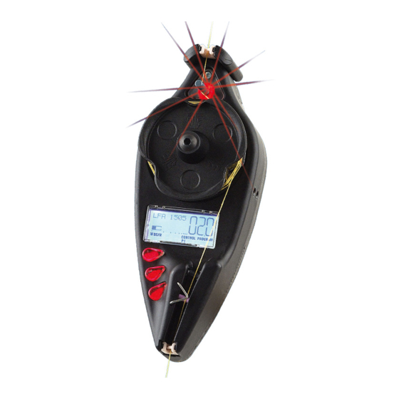
Operation 3 – OPERATION Operating Characteristics of ULTRAFEEDER Devices For programming and control of ULTRAFEEDER devices, 3 push-buttons, 2 signaling red LEDs and a LCD display are available to the operator. 1. RED LEDs (Front side and Read side) Red Led on the front side of device. -
Page 42: Symbols Shown On Lcd
Symbols shown on LCD A – Label Area Indicates the activation of any of the 3 push-buttons of ULTRAFEEDER device. Communication in progress with SMART MATRIX FEEDER/PFU terminal or with the CONTROL Indicates that the ULTRAFEEDER device is operating in Control status. -
Page 43: Functions Directly Available To The Textile Machine Operator
Real-time control of device temperature and current absorbed by the device’s motor. 1) Alarm Reset When a ULTRAFEEDER device detects an Error condition (E2, Tension Error, etc.), the device stops and the LFA nnnn indication on display is replaced by the error message. -
Page 44: Exclusion And Re-Inclusion Of An Ultrafeeder Device
Operation 3) Exclusion and Re-inclusion of an ULTRAFEEDER Device When needed, it is possible to temporarily exclude an ULTRAFEEDER device, in order to avoid undesired starts due to vibrations, etc. To exclude and re-include a device, operate as follows: Exclusion: Press and hold down for 3 seconds The display will show the exclusion confirmation request. -
Page 45: Programming The Ultrafeeder Devices
SIMPLE ADVANCED the ENTER button. To avoid undesired changes of operating parameters, after the installation of ULTRAFEEDER devices and after having setup and checked all the working parameters in programming environment, it is advisable to activate the ADVANCED programming environment, so that when the operator will subsequently enter... -
Page 46: Advanced Programming Of Ultrafeeder Devices
ULTRAFEEDER devices offer 4 advanced programming levels: P1, P2, P3 and P4, clearly indicated in the messages area of LCD during the programming sequences. - Page 47 LANGUAGE SELECTION APPLICATION YARN TYPE STOP POLARITY MOTOR ROTATION UNICO OPERATING MODE FLIP DISPLAY Press the (Control) button to switch from one programming level to the next one. Press (Reset) button to quit the programming environment. ULTRAFEEDER - 3-7 -...
-
Page 48: General Diagram Of P1÷P4 Advanced Programming Levels And Default Settings
Operation General Diagram of P1÷P4 Advanced Programming Levels and Default Settings NOTES: The values shown refer to the default parameters (set by BTSR). LFA = Length of Absorbed Yarn in m/min The selectable languages are Italian, English, French, Spanish, German, Japanese, Chinese. -
Page 49: P1 Programming Level
P1 menu. MAIN TENSION P1.1 Tension value with which the ULTRAFEEDER device must operate to create the desired article. [Allowed values 0.2 ÷ 100.0 grams]. Choose the desired value using: (to increase the value) or (to decrease the value). - Page 50 Operation Example 1: Main Tension: 2.0 g Error Tension: ± 0.5 g Example 2: Main Tension: 5.0 g Error Tension: ± 2.0 g Example 3: Main Tension: 5.0 g Error Tension: ± 6 g - 3-10 - ULTRAFEEDER...
- Page 51 [Allowed values 0.1 ÷ 25.0 grams]. to return to the beginning of P1 menu. to switch to P2 menu. to return to CONTROL status without programming P2, P3 and P4 menus. ULTRAFEEDER - 3-11 -...
-
Page 52: P2 Programming Level
P2.3 = S (Standard) The parameter 2.2 indicates the amount of yarn fed during the stop phase. This function allows relaxing the yarn, each time the ULTRAFEEDER device stops running. The value set with this parameter corresponds to the number of revolutions carried... - Page 53 (to decrease the value). to confirm. P2.3 = A (Advanced): The parameter 2.2 indicates the tension, the ULTRAFEEDER shall operate with when the motor speed is lower than the speed indicated on parameter 2.3. [Allowed values 0.1 ÷ 95.5 gr].
-
Page 54: Example Of Relax Yarn And Relax Speed Parameters Interaction
U-FEEDER Operating Tension Yarn Guide Entry During the operation with nominal yarn feeding speed (V = 100 m/min), the ULTRAFEEDER device operates with the tension set in MAIN TENSION (A), after a speed change and/or a thread guide exit condition, the feeding speed decreases following a deceleration ramp and, when it reaches the value programmed in RELAX SPEED (03 = 10 m/min in the example above) the device will carry out a wheel rotation by the number of revolutions set on P2.2,... -
Page 55: P3 Programming Level
OFFSET P3.1 This function is used to adjust the mechanical clamping position of ULTRAFEEDER device. It clears possible measurement errors due to the different clamping position of the device on textile machine. The displayed indication is the actual value resulting from the clamping position of the device. - Page 56 MATRIX FEEDER/PFU terminal using the serial communication port, however in particular circumstances (for instance after the replacement of a ULTRAFEEDER device), it may be useful to set the code operating directly on the new device. to return to the beginning of P3 menu.
-
Page 57: P4 Programming Level
APPLICATION SELECTION P4.2 This function allows you to choose one of the pre-defined applications. The behavior of ULTRAFEEDER device (e.g. reaction to INC/DEC pulses) will depend on the chosen application. to scroll forward/backward the list of available applications: –... - Page 58 MOTOR-D P4.5 This function allows you to select the ULTRAFEEDER device motor rotation direction. Keep the button pressed for 3 seconds to change the motor rotation direction (CW = clockwise rotation;...
- Page 59 Operation OPERATING MODE P4.7 This function allows you to choose the operating mode of ULTRAFEEDER devices. to scroll up or down the list of available modes: – 1 – 2 – 1 – MASTER MASTER SLAVE SLAVE (OFF= Master/Slave mode deactivated) to confirm the options shown on display and move to the next parameter.
- Page 60 Masters (Master 1 and Master 2); an unlimited number of Slaves can be assigned to each Master. The Master/Slave mode can be configured both: for applications using only ULTRAFEEDER devices and for applications using different device types, as shown on the following table. MASTER...
-
Page 61: Inc/Dec Programmable Commands
Applications: SOCKS,REVERSE SOCKS, PANTYHOSE, SEAMLESS, KNIT, FLAT KNIT, REVERSE KNIT, SEWING, SMALL LOOM, RASCHEL Immediate graduation reset, as soon as the INC/DEC signals are simultaneously de-activated; “Error Tension” Alarm active only when ULTRAFEEDER operates with P1 Tension ( MAIN TENSION Immediate... -
Page 62: Application: Medical Socks
Operation Application: MEDICAL SOCKS Reset of graduated tension synchronized through a defined sequence of INC/DEC (deactivation/activation/deactivation); “Error Tension” Alarm active only when the ULTRAFEEDER device operates with P1 tension. Graduations Reset The A and B pulses, must not necessarily have the same duration, however it is important that their duration is not less than 60 msec. -
Page 63: Management Of "Tension Error" Alarm
Operation Management of “Tension Error” Alarm EXAMPLE The ULTRAFEEDER generates the “Error Tension” Alarm when the tension goes out of the programmed tolerance band and automatically resets the alarm as soon as the tension returns within the programmed tolerance band. -
Page 64: Characteristics And Performance Of Unico And Unc.sr Accessories
With reference to the figure shown on next page, such operation principle can be summarized as follows: the yarn (A), prior to be coiled around the wheel of ULTRAFEEDER device, passes through a swinging arm (B), controlled by an internal spring, which reacts in real time to the abrupt yarn absorption variations, either moving down (to release the yarn) or moving up (to retain the yarn). -
Page 65: Fitting The Unico And Unc.sr Accessories To The Ultrafeeder Device
Operation Fitting the UNICO and UNC.SR Accessories to the ULTRAFEEDER Device Applications Applications with “Reverse” without “Reverse” ULTRAFEEDER - 3-25 -... -
Page 66: Customization And Order Codes Of Unico Accessory
(Spring for UNICO, 0.5 yarn with ceramic) (Spring for UNICO, 0.6 yarn with ceramic) Other Product code N° Code Description REV. Q.ty UNICO B Basic Dynamic Compensator UNC/08 0.8 mm knot catcher blade UNC.SP.001 Spring for UNICO, 0.4 yarn with ceramic - 3-26 - ULTRAFEEDER... -
Page 67: Chapter 4 - Ultrafeeder Troubleshooting And Maintenance
ULTRAFEEDER Troubleshooting and Maintenance 4 – ULTRAFEEDER TROUBLESHOOTING AND MAINTENANCE Indications Provided by the Red LEDs on ULTRAFEEDER Device Status of ULTRAFEEDER device Front Rear Identification BLINKING GREEN/RED ALTERNATE FLASHING ERROR E2 BLINKING GREEN/RED ALTERNATE FLASHING MOTOR LOCKED (with CONTROL button) -
Page 68: Troubleshooting On Ultrafeeder Devices
(max 1 bar) display 2) Perform a correct adjustment of the OFFSET 2) OFFSET value of value on ULTRAFEEDER device as described on ULTRAFEEDER device out of page 3.15. adjustment ES ES-CONT 1) Internal protection against 1) Reset the alarm;... - Page 69 4) Wiring problem 4) If the stop led on ULTRAFEEDER and the corresponding stop led on KTF/PW4 power supply turn on, when the yarn breaks, check the machine connecting cables.
-
Page 70: Useful Hints When Using The Ultrafeeder Device On Socks Or Pantyhose Production Machines
If the fault is not included in this table, please contact your local BTSR reseller, giving a detailed description of the kind of fault and the conditions in which it occurred. In the case where the BTSR Technical Service intervention would be required, before calling it is suggested to take note of the code printed on the faulty device, as this information will make diagnoses for the BTSR technicians easier. -
Page 71: Ordinary Maintenance
ULTRAFEEDER Troubleshooting and Maintenance Ordinary Maintenance The ULTRAFEEDER devices do not require special maintenance interventions, except a periodical cleaning, depending on the environment condition in which they operate. For cleaning purposes, do not use solvent, but rather a soft cloth dampened with neutral detergent or alcohol. - Page 72 ULTRAFEEDER Troubleshooting and Maintenance Page intentionally left blank - 4.6 - ULTRAFEEDER...
-
Page 73: Chapter 5 -Ytt Device
YTT Device 5 – YTT DEVICE System description The YTT device (BTSR patent) is an optional accessory which can be connected to the ULTRADFEEDER device and allows improving performance using 2 different operating modes, described on the following pages. Mechanical installation on ULTRAFEEDER Note: For the meaning of YTT/TT and YTT/SS modes, please refer to the following paragraph “Operating modes”... -
Page 74: Connection
YTT Device Connection The YTT device must be connected to the ULTRAFEEDER device using the MA8/10/2FE10/CAN cable, as shown on the following figure: MA8/10/2FE10/CAN cable ULTRAFEEDER If the adapter cap is installed on the ULTRAFEEDER device connector (see: ULTREFEEDER device electrical interface on chapter2), it is necessary to remove it to connect the MA8/10/2FE10/CAN cable. -
Page 75: Operating Modes
At this point the 2 devices are uniquely associated. Operating modes The YTT device can operate in 2 different modes: Recovery mode Stretch mode. The operating mode is automatically acquired according to the application set on the ULTRAFEEDER device (parameter P4.2). ULTRAFEEDER - 5.3 -... - Page 76 REVERSE SOCKS FLAT KNIT With this choice the YTT device motor works in electric axis mode with the ULTRAFEEDER device in order to keep the yarn stretched between the first and the second wheel. When the machine returns the yarn, this is recovered by the associated YTT device.
- Page 77 [Allowed values -95.0% ÷ +25.0%]. Positive values indicate that the YTT device motor will turn faster than the ULTRAFEEDER device, while negative values indicate that the YTT device motor will turn more slowly than the ULTRAFEEDER device. The value indicated on the parameter indicates the percentage of speed difference.
- Page 78 YTT Device Page intentionally left blank - 5.6 - ULTRAFEEDER...
- Page 79 4 LEDs start blinking. Press the ENTER button to start the firmware upgrade. During the upgrading stage, the 4 indicated LEDs start blinking in sequence one at a time until the procedure is completed: NEXT CYCLE START/STOP ULTRAFEEDER - A.1 -...
- Page 80 If the LEDs stop blinking, the error has been recovered If the LEDs continue blinking, please contact the BTSR Service Department. In some error situations it could be necessary to reset the PFU/64FS power supplier, operating as follows: Disconnect the green power connector (A)
- Page 81 DISTRIBUTOR BTSR International S.p.A. Via S. Rita 21057 OLGIATE OLONA (VA) Tel. 0331-323202 Fax 0331-323282 Internet: www.btsr.com REV. 4.1 – 02/17...
Need help?
Do you have a question about the ULTRAFEEDER and is the answer not in the manual?
Questions and answers