
Subscribe to Our Youtube Channel
Related Manuals for btsr SMART 200 TTS


Summary of Contents for btsr SMART 200 TTS
- Page 1 SMART 200 TTS & IS3W/TTS YARN CONTROL SYSTEM Operating Manual ENGLISH Rev. 2.0 – August 2003...
- Page 2 Copyright 2003 - BTSR – All rights reserved. This manual is intended for the users of the SMART 200 TTS system. It is suggested to carefully read the instructions described in this manual before making the connections and use the system.
-
Page 3: Table Of Contents
Sensor - System................................3.8 Electrical Characteristics of STOP Signal ......................3.9 Parameters that affect the sensor detection features ....................3.10 Preliminary operations for using the SMART 200 TTS terminal ...............3.12 Operating Sequences..............................3.13 Enabling the SETUP Menu Functions (CONFIG)....................3.14 Enabling the SETUP Menu Functions (NEW, MODIFY, ERASE)..............3.15 Enabling the WORK Menu Functions ........................3.16... - Page 4 SENSOR TEST Sensors Test..........................3.31 COM TEST Testing the Efficiency Rate over the Communications Line between the SMART 200 TTS Terminal and Sensors................3.32 VERS UPG Test of software version and Sensor’s version Updating .............3.33 Creating a New Article......................3.34 SPEED - Creating a New Article - Machine collection speed ..........3.36 TPXmax -Creating a New Article –...
-
Page 5: Intro Uction
INTRODUCTION INTRODUCTION Congratulations for choosing a BTSR product. With our SMART 200 TTS yarn control system, you got an innovative, unique solution, able to offer you multiple advantages concerning quality control of your production. SMART 200 TTS has been designed for application on textile machines such as twisters for tyrecord, carpet, etc., that during the working process need a dedicated... - Page 6 (CONT), pulse ST-cP CP = pulse signal signal 2 seconds (P2s) or pulse signal 10 seconds (P10s) Alternative items: Within the description of configuration/programming procedures the alternative screen shots are shown with this bracket symbol. - I.2 - SMART 200 TTS...
-
Page 7: Chapter 1 Overview
Special Features of SMART 200 TTS system The SMART 200 TTS system has a set of unique features which make it a true microcomputer dedicated to the yarn quality control. -
Page 8: General Features Of Smart Systems
The system allows connecting up to 200 yarn quality control sensors of the IS3W/TTS series. Easy Monitoring Besides the information shown on graphical display of SMART 200 TTS, each IS3W/TTS sensor has a red LED that, when flashing, indicates the type of fault detected. -
Page 9: Technical Data And Installation
10° - 60 °C Installation The installation of the SMART 200 TTS system depends on the type of application and on the number of sensors to be connected. When the number of sensors is limited, it is possible to connect them directly to the SMART terminal, otherwise it is necessary to use a stabilised power supply PSU 10A. -
Page 10: Interface Connectors On Smart 200 Tts
Technical data and Installation Interface Connectors on SMART 200 TTS Concerning all electrical systems, it is a recommended rule to ensure that the ground cable (GND) is connected to the sensor support. - 2.2 - SMART 200 TTS... -
Page 11: Example Of Generic Application Connection
Technical data and Installation Example of Generic Application Connection Concerning all electrical systems, it is a recommended rule to ensure that the ground cable (GND) is connected to the sensor support. SMART 200 TTS - 2.3 -... -
Page 12: Connection Cables And Power Supply Devices
Technical data and Installation Connection Cables and Power Supply Devices To correctly install the SMART 200 TTS system and sensors, it is necessary to use a certain number of connecting cables provided by BTSR; their length and type depend on the specific requirements and application types. -
Page 13: Chapter 3 Operation
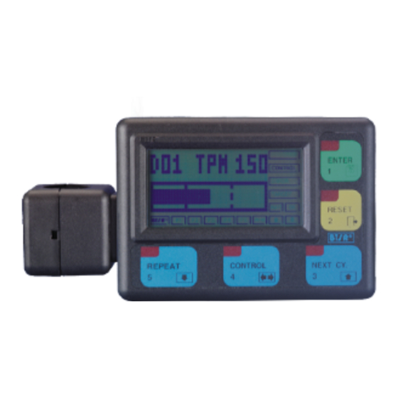
OPERATION SMART 200 TTS Terminal Features As in all SMART BTSR systems, the operation of SMART 200 TTS system is controlled by just 5 membrane buttons and it is monitored by a LCD graphic display, which guides the operator through all programming and administration phases of the system, by means of straight-forward messages which can be understood clearly and immediately. - Page 14 When entering numeric data (for example the number of sensors) it allows you to decrease the numeric value of the field. If it is held down continuously the numeric field decrements more rapidly. - 3.2 - SMART 200 TTS...
- Page 15 ENTER button, while to do the opposite, i.e. going from a lower to an upper level you must press the RESET button. SMART 200 TTS -3.3 -...
-
Page 16: Is3W/Tts Sensor Features
(under both static and dynamic conditions) which, thanks to an innovative patented technique (Smart Scanning Sensor) combined to the advanced yarn control terminal SMART 200 TTS don't need complex wirings and long installation times, allowing you to manage up to 200 positions. -
Page 17: Technical Characteristics Of Is3W/Tts Sensor
" Close the small cover and secure the sensor using M3 screws. Ensure that the yarn runs in the middle of detection area SMART 200 TTS -3.5 -... -
Page 18: Installation Of Is3W/Tts Sensors With Built-In Cable
To switch the touch light, just skim it with a finger. 2 signally Leds (green ad red) indicating the sensor’s status (initial numbering status, normal operation status, failure condition and type of failure). Touch Light (embedded green and red Leds) - 3.6 - SMART 200 TTS... -
Page 19: Touch Light Function
Indicates a sensor fault (e.g. Loss of stored data). Red LED FLASHING Try to reprogram the sensor. If the fault remains, replace the sensor (*) for more details, please refer to paragraph “Parameters that affect the sensor detection features” page 3.10 SMART 200 TTS -3.7 -... -
Page 20: Sensor - System
Operation Sensor –System Interface The sensor communicates with SMART 200 TTS terminal and with the textile machine through the following signals: TX-RX: Is the bi-diretional communication line between sensor and SMART terminal, used for sensor operation parameters programming, for sensor’s test and for all the other real-time communications between sensor and terminal. -
Page 21: Electrical Characteristics Of Stop Signal
Auto. Electrical Characteristics of STOP Signal Protected against short circuit Max DC current at collector: 200 mA Max peak current at collector: 500 mA Vce = 1,2V with I_collector = 500 mA SMART 200 TTS -3.9 -... -
Page 22: Parameters That Affect The Sensor Detection Features
SMART 200 TTS system: SPEED (yarn collection speed in meters per minute) - Page 23 This parameter indicates wherever the sensor, after having detected a failure, must be reset manually (Touch Light) or automatically, providing that the error condition disappears. K FACT This function allows setting a correction factor (multiplier or divisor) on twisting number, to meet specific user’s conditions. SMART 200 TTS -3.11 -...
-
Page 24: Preliminary Operations For Using The Smart 200 Tts Terminal
> CONTROL to enable automatic monitoring. > GRAPH to activate the graphic visualisation mode Pressing the Reset button when the system displays any of the main menu items, the current software version (BTSR VER. X.X) will be displayed. - 3.12 - SMART 200 TTS... -
Page 25: Operating Sequences
Operation Operating Sequences The SMART 200 TTS system allows the following set of functions to be carried out: Univocal identification of each sensor by means of an automatic numbering procedure. Programming, modifying, controlling and saving the values related to the different articles, by means of a database which can manage up to 40 different articles. -
Page 26: Enabling The Setup Menu Functions (Config)
Operation Enabling the SETUP Menu Functions (CONFIG) - 3.14 - SMART 200 TTS... -
Page 27: Enabling The Setup Menu Functions (New, Modify, Erase)
Operation Enabling the SETUP Menu Functions (NEW, MODIFY, ERASE) SMART 200 TTS -3.15 -... -
Page 28: Enabling The Work Menu Functions
Operation Enabling the WORK Menu Functions Enabling the GRAPH Menu Functions - 3.16 - SMART 200 TTS... -
Page 29: Control Function
DEV nnn TL xxx Number of “ Insufficient Twisting ” faults on device nnn DEV TOT TH xxx Total number of “Excessive Twisting” faults DEV TOT TL xxx Total number of “ Insufficient Twisting” faults SMART 200 TTS -3.17 -... -
Page 30: Device Parameters Setting For Initial Installation
The number ZZZ is increased by 1 unit. Once all the sensors have a unique number assigned, the DEVICE CONFIG message re-appears. Press once to return to the Setup/Programming menu, or press it twice to return to the Main Menu. - 3.18 - SMART 200 TTS... -
Page 31: Tt-Tb
Either TT-WAIT - TT PRG OK or TB WAIT - TB PRG OK, will appears to indicate that the function has been correctly programmed. Press once to return to CONFIG Menu, or twice to return to Main Menu. SMART 200 TTS -3.19 -... -
Page 32: Tp-Ims Configuration Of Winding Measurement Unit: Twisting Per Second/Meter/Inch
The capital letter indicates the current selection: imS = Twisting (Balloon) / Second iMs = Twisting (Balloon) / Meter Ims = Twisting (Balloon) / Inch Press once to return to CONFIG Menu, or twice to return to Main Menu. - 3.20 - SMART 200 TTS... -
Page 33: Mo-Ctr Configuration Of System Operation In Either Monitor Mode Or Control Mode
= moves the cursor from XXX field to YYY field = increases the field pointed by the cursor = decreases the field pointed by the cursor Sensors before XXX and after YYY will automatically be programmed in Control mode. SMART 200 TTS -3.21 -... - Page 34 Operation If you change the XXX ÷ YYY range, the SMART 200 TTS terminal will automatically update the situation, thus bringing back to Control mode the sensors which are no longer included in the new range. Only one XXX ÷ YYY range may be programmed.
-
Page 35: Res-Ma Configuration Of Sensor Reset Mode: Automatic/Manual
Either MANUAL WAIT, MANUAL PRG OK, or AUTO WAIT, AUTO PRG OK will appear to indicate that the function has bees correctly programmed. Press once to return to the CONFIG menu, or twice to return to the Main Menu. SMART 200 TTS -3.23 -... -
Page 36: Lk-Ulk Enabling/Disabling The Touch Light Button Operation
Either UNLOCK WAIT - UNLOCK PRG OK or LOCK WAIT - LOCK PRG OK will appear to indicate that the function has been correctly programmed. Press once to return to the CONFIG menu, or twice to return to the Main Menu. - 3.24 - SMART 200 TTS... -
Page 37: St-Nco Configuring The Level Of Stop Signal As Normally Closed Or Normally Open
WAIT and STOP - NO PRG OK or STOP - NC WAIT and STOP - NC PRG OK to indicate that the function has been programmed correctly. Press once to return to the CONFIG menu, or twice to return to the Main Menu. SMART 200 TTS -3.25 -... -
Page 38: St-Cp Configuration Of Stop Output As: Continuous Or Pulse Signal
ST-P2s WAIT and ST-P2s PRG OK or ST-P10s WAIT and ST-P10s PRG OK to indicate that the function has been programmed correctly Press once to return to the CONFIG menu, or twice to return to the Main Menu. - 3.26 - SMART 200 TTS... -
Page 39: D_Cntr Configuration Of Sensor Delay Time Before Entering The Control Status
At the start-up, or after a fault reset, the green Led will flash for a time corresponding to the set delay, then it will remain permanently lit. Press once to return to the CONFIG menu, or twice to return to the Main Menu. SMART 200 TTS -3.27 -... -
Page 40: K Fact Configuration Of Correction Factor For Twisting Computation
Set the desired value (-5 … +5) using Press to confirm the entered value. Press once to return to the CONFIG menu, or twice to return to the Main Menu. - 3.28 - SMART 200 TTS... -
Page 41: Keycode Password To Access Setup And Work Menus
WARNING: If you set a password (Keycode) it is necessary to enter it each time you access SETUP and WORK. If you forget the access code it will be necessary to contact your BTSR reseller. SMART 200 TTS -3.29 -... -
Page 42: Clock Reading/Setting The Printer Clock-Calendar (Rtc)
CONFIG menu, or twice to return to the Main Menu. If the printer is not connected correctly, the ERR-COM PRINTER message will appear. For further details, please refer to chapter al Cap. 4 “Troubleshooting”. - 3.30 - SMART 200 TTS... -
Page 43: Sensor Test Sensors Test
SENSOR This function gives you the possibility to check communications between the SMART 200 TTS terminal and (one by one) each of the connected sensors. In this way it is possible to check that: All sensors are correctly numbered and identified All sensors respond correctly to the terminal The same number has not been assigned to more that 1 sensor. -
Page 44: Com Test Testing The Efficiency Rate Over The Communications Line Between The Smart 200 Tts Terminal And Sensors
TEST This function allows you to check the perfect operation of the communications line between the SMART 200 TTS Terminal and connected Sensors. It is advisable to run this check during the first testing phase (immediately after installation) and each time random problems occur in the system operation, which... -
Page 45: Vers Upg Test Of Software Version And Sensor's Version Updating
This function allows you to check the software version on each individual sensor, with the possibility to update the version, if needed.. The updating procedure is effective only if all the sensors have a software version ≥ 3.0 and only if strictly necessary, for instance upon indication of your BTSR distributor. Press until the TEST CONFIG menu option is displayed. -
Page 46: New Creating A New Article
If you enter a name already existing, the warning message DOUBLE NAME will be displayed. In this case press and enter a new name. - 3.34 - SMART 200 TTS... - Page 47 Operation Now you will have to program the sequence of control parameters related to the article being created: SPEED TPX MAX TPX MIN SENS FILTER TIMEer SMART 200 TTS -3.35 -...
-
Page 48: Speed - Creating A New Article - Machine Collection Speed
Maximum Number of Twisting per Second/Meter/Inch SETUP TPXmax Press to have access to the function. Set the Maximum Number of Twisting per Second/Meter/Inch (nnn), using Press to confirm Press to select the next parameter (TPXmin) - 3.36 - SMART 200 TTS... -
Page 49: Sens - Creating A New Article Sensitivity
Set the Sensor Sensitivity depending on the article being created (1 = Minimum Sensitivity ……8 = Maximum Sensitivity), using Press to confirm Press to select the next parameter (FILTER) SMART 200 TTS -3.37 -... - Page 50 Once to have configured all the parameters related to the article being created, press to save the article parameters Press to save the article to the SMART 200 TTS system’s database, or press to leave the function without saving the article. - 3.38 -...
-
Page 51: Modify Modifying An Existing Article
During the erase process, the OK WAIT ERASE message is displayed . At the end of the Erase operation, press once to return to >ERASE CONFIG screen, or twice to return to the Main Menu. SMART 200 TTS -3.39 -... -
Page 52: Scan Displaying Articles Currently Loaded In The Sensors
WORK SCAN This function allows the display of articles which are loaded into the sensors connected to SMART 200 TTS system. Press to have access to the function. The screen shows the first article loaded in the sensors connected to the SMART 200 TTS system. -
Page 53: Load Loading An Article In Sensor Memory
LOAD This function allows loading of an article (more specifically the settings of the article) on a specified range of sensors connected to the SMART 200 TTS system. The sensors must have been previously declared and numbered using the CONFIG... -
Page 54: Unload Unloading Articles From The Sensor Memory
>UNLOAD SCAN screen or two times to return to Main Menu. The END UNLOAD message means that all articles have been unloaded from the sensors connected to the SMART 200 TTS system. - 3.42 - SMART 200 TTS... -
Page 55: Bar Graph Graphic Visualisation Of Twisting Number Detected By Each Is3W/Tts Device
Press to activate the graphic display. Increments yy Decrements yy Selects the TPX measurement unit: TPS = Twisting per Second TPM = Twisting per Meter TPI = Twisting per Inch Press to exit. SMART 200 TTS -3.43 -... -
Page 56: Istog Graph Graphic Visualisation (Comparison) Of Twisting Detected By Multiple Is3W/Tts Devices
Selectable with BARS = 12 TPXmax threshold Selectable with TPXmin threshold REF + 1 ......REF + 11 BARS = 16 TPXmax threshold Selectable with TPXmin threshold REF + 1 ......REF + 15 - 3.44 - SMART 200 TTS... - Page 57 Choose the number of bars (sensors) to be displayed (8-12-16) using Press to activate the graphic display. Press once to exit the graphic function and return to REF nnn BARS x screen or 2 times to return to the main menu. SMART 200 TTS -3.45 -...
-
Page 58: Print Report Production Report Printing
When the printing is completed, the REPORT xxx, yyy screen will re-appear, allowing you to select a new sensor range for report printing. In case of communication error between SMART 200 TTS terminal and printer, an ERR_COM PRINTER error message will appear. - Page 59 Operation Production Report Example SMART 200 TTS -3.47 -...
- Page 60 Operation Page intentionally left blank - 3.48 - SMART 200 TTS...
-
Page 61: Troubleshooting And Maintenance
DEV XX screen If the fault is not included in the above table, please contact your local BTSR reseller, giving a detailed description of the kind of fault and the conditions in which it occurred. In the case where the... -
Page 62: Ordinary Maintenance
Troubleshooting and Maintenance Ordinary Maintenance The SMART 200 TTS system does not require special maintenance interventions. Although it is important to periodically clean the sensors and the terminal according to the environment conditions in which the system operates. The IS3W/TTS Sensors are equipped with a function of automatic compensation, which allows the detection features to remain unaffected even when some traces of dirt are present. -
Page 63: Updating The Software Version On Smart Terminals
Troubleshooting and Maintenance Updating the Software Version on SMART Terminals The software updating on BTSR SMART terminals is a relatively easy operation. However it must be carried out following scrupulously the instructions given in this manual and using the indicated tools to avoid damaging the equipment and/or microprocessor contacts. -
Page 64: Product Summary Tables
FILTER TIMEer Article …………………. SPEED … m/min Parameter Value TPS (M)(I) Max TPS (M)(I) Min SENS FILTER TIMEer Article …………………. SPEED … m/min Parameter Value TPS (M)(I) Max TPS (M)(I) Min SENS FILTER TIMEer - 4.4 - SMART 200 TTS... - Page 65 FILTER TIMEer Article …………………. SPEED … m/min Parameter Value TPS (M)(I) Max TPS (M)(I) Min SENS FILTER TIMEer Article …………………. SPEED … m/min Parameter Value TPS (M)(I) Max TPS (M)(I) Min SENS FILTER TIMEer SMART 200 TTS - 4.5 -...
- Page 66 Troubleshooting and Maintenance Page intentionally left blank - 4.6 - SMART 200 TTS...
-
Page 67: Appendix A - Quick Reference
QUICK REFERENCE The following flow-charts show briefly the operating sequences which are required to complete all the functions available on the SMART 200 TTS system. The use of the quick reference guide supposes that the user has already acquired a certain ability in handling the system, therefore there are no detailed explanations of each screen shot;... - Page 68 Appendix A - Quick Reference Symbols Key - A.2 - SMART 200 TTS...
- Page 69 Appendix A - Quick Reference Symbols Key SMART 200 TTS - A.3 -...
- Page 70 Appendix A - Quick Reference Symbols Key - A.4 - SMART 200 TTS...
- Page 71 Appendix A - Quick Reference Symbols Key SMART 200 TTS - A.5 -...
- Page 72 Appendix A - Quick Reference Symbols Key - A.6 - SMART 200 TTS...
- Page 73 Appendix A - Quick Reference Symbols Key SMART 200 TTS - A.7 -...
- Page 74 Appendix A - Quick Reference Symbols Key - A.8 - SMART 200 TTS...
- Page 75 Appendix A - Quick Reference Symbols Key SMART 200 TTS - A.9 -...
- Page 76 Appendix A - Quick Reference Symbols Key - A.10 - SMART 200 TTS...
- Page 77 Appendix A - Quick Reference Symbols Key SMART 200 TTS - A.11 -...
- Page 78 Appendix A - Quick Reference Symbols Key - A.12 - SMART 200 TTS...
- Page 79 Appendix A - Quick Reference Notes: SMART 200 TTS - A.13 -...
- Page 80 Appendix A - Quick Reference Page intentionally left blank - A.14 - SMART 200 TTS...
- Page 81 DISTRIBUTOR BTSR International S.p.A. Via S. Rita 21057 OLGIATE OLONA (VA) Tel. 0331-323202 Fax 0331-323282 Internet: www.btsr.com REV.2.0 – 08/03...
Need help?
Do you have a question about the SMART 200 TTS and is the answer not in the manual?
Questions and answers