Table of Contents
Advertisement
Quick Links
- 1 Connections and Electrical Interface
- 2 Pc ↔ Smart Matrix ↔ Sm-Din Connection
- 3 Smart Matrix ↔ Sm-Din ↔ Is3W/Mtc Connection
- 4 Smart Matrix Mtc Operation
- 5 Errors Shown on Display of Sm-Din Boards
- 6 ID and Transmission Speed Configuration on each Sm-Din Board (P01 - P02 Parameters)
- Download this manual
Advertisement
Table of Contents

Related Manuals for btsr SMART MATRIX MTC


Summary of Contents for btsr SMART MATRIX MTC
- Page 1 SMART MATRIX MTC Operating Manual ENGLISH Rev. 1.0 – September 2010...
- Page 2 SMART MATRIX MTC - Rev. 1.0 - September 2010 Copyright - BTSR – All rights reserved. This manual is entrusted to the users of SMART MATRIX MTC system developed for control/monitoring activities of doubling machines, winding machines, etc equipped with control (IS3W) sensors. You are kindly recommended to thoroughly read the instructions provided by this manual prior to connect and use the system.
- Page 3 Introduction...
- Page 5 Introduction Congratulations for choosing a BTSR product. With our SMART MATRIX MTC yarn control system, you got an innovative, unique solution, which offers you multiple advantages concerning the quality control of your production. SMART MATRIX MTC has been designed to obtain an accurate measurement of yarn meters wound on doubling machines, winding machines, etc.
- Page 6 Section 2 – provides the operating instructions for a correct use of the SMART MATRIX MTC terminal as well as the parameter configuration/programming instructions and data/errors display facilities.
-
Page 7: Table Of Contents
SMART MATRIX ↔ SM-DIN ↔ IS3W/MTC Connection ................1-2 SM-DIN ↔ Machine Interface ........................1-3 Interfaccia Sensori ............................. 1-4 SMART MATRIX ↔ SM-DIN/PC Interface....................1-5 SMART MATRIX MTC Generic Application Diagram................1-6 2 – Operating instruction SMART MATRIX MTC Operation......................2-1 Navigation throughout the Display Windows ..................... 2-2 1 –... - Page 8 SMART MATRIX/SMDIN/MTC Board technical characteristics ..............3-2 ID and Transmission Speed Configuration on Each SM-DIN Board (P01 - P02 Parameters)....3-3 IS3W/MTC Sensor Features ........................3-4 Function of the IS3W/MTC Sensors ......................3-4 Interface Specifications..........................3-5 SMART MATRIX MTC - iv -...
-
Page 9: Connections And Electrical Interface
Connections and Electrical Interface... -
Page 11: Pc ↔ Smart Matrix ↔ Sm-Din Connection
ID and Transmission Speed Configuration on Each SM-DIN Board on Section 3. On all electrical systems, you are kindly recommended to connect the ground cable (GND) to the support on which the devices are installed. SMART MATRIX MTC 1 - 1... -
Page 12: Smart Matrix ↔ Sm-Din ↔ Is3W/Mtc Connection
The following diagram shows the connection of IS3W/MTC Sensors to SM-DIN Boards, as well as the connection between SM-DIN Boards and SMART MATRIX. MA2/FE FORK CABLE CONNECTION EXAMPLE MAX 100 SENSORS FLAT CABLE CONNECTION EXAMPLE MAX 100 SENSORS SMART MATRIX MTC 1 - 2... -
Page 13: Sm-Din ↔ Machine Interface
The following diagram shows the electrical interface (pin assignment) of SM-DIN Board. The sensor interface is shown on the following page. Machine Interface (INPUT) Power Supply (*) Machine Interface (OUTPUT) Recommended power supply: 24 Vdc. SMART MATRIX MTC 1 - 3... - Page 14 SM-DIN nn Module – (Identified by means of Edt function directly on the SM-DIN module) Sensors Sensors Max 100 IS3W/MTC sensors Sensors Sensors The number of IS3W sensors actually connectable to the Board, depends on the capacity of power supply system used. SMART MATRIX MTC 1 - 4...
-
Page 15: Smart Matrix ↔ Sm-Din/Pc Interface
SMART MATRIX SM-DIN/PC Interface SMART MATRIX ↔ SM-DIN/PC Interface The following figure shows the electrical interface (pin assignment) of SMART MATRIX MTC terminal. The “Printer” and “USB” connectors are not currently used for MTC application. Port for software upgrade SM-DIN/MTC... -
Page 16: Smart Matrix Mtc Generic Application Diagram
SMART MATRIX QUILT Generic Application Diagram SMART MATRIX MTC Generic Application Diagram (*) The MACHINE STOP signal can be obtained either from the SM-DIN Boards or from the SMART MATRIX terminal. SMART MATRIX MTC 1 - 6... -
Page 17: Operating Instruction
Operating Instructions... -
Page 19: Smart Matrix Mtc Operation
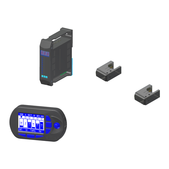
SMART MATRIX MTC Operation All the Configuration, Parameter Setting, Data & Error Display operations, etc. can be managed by the Operator in quick and intuitive way, using the SMART MATRIX MTC control terminal. The SMART MATRIX ↔ Operator interface consists of: A - Graphic display showing: •... -
Page 20: Navigation Throughout The Display Windows
SMART MATRIX MTC Operation Navigation throughout the Display Windows Many configuration/parameter setting functions of SMART MATRIX system require a number of parameters distributed among multiple display windows. All the “Window Selection”, “Parameter Selection within a Window” and “Parameter Setting” functions on SMART MATRIX terminal, can be carried out using exclusively the multi-function Rotary Selector, through a navigation technique based upon “Pointing”, “Selecting”... -
Page 21: Navigation Inside The Selected Window (Std)
SMART MATRIX MTC Operation 1 – Navigation inside the Selected Window (STD) Turn the selector to “Point” in sequence the various items of the window → → → (STD TARGET DELAY START DELAY COUNT→ SENSITIVITY→ DELAY STOP → CORRECTION→ RECOVERY). -
Page 22: Windows Swap
SMART MATRIX MTC Operation 2 – Windows Swap Turn the selector to “Point” the label of the current window (STD) and click to select it. Esempio: Label highlighted Turn the selector to “Point” the window → ADV). (ATD Label highlighted... -
Page 23: Entering Alphanumeric Values
SMART MATRIX MTC Operation 3 – Entering Alphanumeric Values To entering alphanumeric values, see for example the USERNAME PASSWORD setting function (KEY CODE). To enter the desired name and password, operate as follows: Select the desired field (e.g.: USERNAME) Turn the selector to choose the first letter of the name . -
Page 24: Immediate Function Activation Through The Smart Matrix Buttons
SMART MATRIX MTC Operation Immediate Function Activation through the SMART MATRIX Buttons The 6 blue buttons (B1 ~ B6) allow you to directly activate some system functions without passing through the menu items. Such functions are indicated by the icons associated with the buttons, as shown on the following figure. -
Page 25: Interpretation Of Operating Screens
SMART MATRIX MTC Operation Interpretation of Operating Screens • System working in Control status • No errors detected! • Broken yarn failure (BROKE) ) detected by sensor No Alternating (DEV 04) mounted on section No 1 (SECT.01), machine side No 1... -
Page 26: Smart Matrix Mtc Menu Structure
SMART MATRIX MTC Menu Structure SMART MATRIX MTC Menu Structure Alternating Error Error details Main Menu Style Database management System Configuration Speed Loading Speed Database Position Style Loading management In the description of the various functions, the following graphic symbols will be used: Turn the selector to “point”... -
Page 27: Sensor Configuration And Numbering
Board and so on for all the Boards used. Once you have configured all the Boards. For instance, let suppose now to configure an application comprising 6 IS3W sensors only, SAVE to save the settings. SMART MATRIX MTC 2 - 9... - Page 28 (*)The totale number of configured devices (MACHINE SIDES SECTIONS PER SIDE DEV. PER SECTION) must match the total number of devices previously set on BOARDS CONFIGURATION screen. Otherwise a “DEVICE NUMBER MISMATCH” error message will appear” SMART MATRIX MTC 2 - 10...
- Page 29 • Shim the touch light of the relevant sensor; the sensor’s led changes from flashing green to red. To quit the identification procedure after the sensor re- numbering. EXIT to return to configuration menu. SMART MATRIX MTC 2 - 11...
-
Page 30: Dacs Devices Configuration And Numbering (Option)
DACs to be numbered. • Shim the touch light of the relevant DAC and continue with the numbering of all DACs. At the end of the numbering operation, the configuration menu will re-appear. SMART MATRIX MTC 2 - 12... -
Page 31: Smart Matrix Code
BACK to return to the previous screen without saving, EXIT to return to menu. Since the SMART MATRIX MTC application uses only one terminal, always set 1 as identification code. SMART MATRIX MTC 2 - 13... -
Page 32: Input/Output Configuration On Sm-Din/Smart Matrix
(STOP1, STOP2) within window, as or NC. To activate the save function. SAVE to save the choice, BACK to return to the previous screen without saving, EXIT to return to menu. SMART MATRIX MTC 2 - 14... - Page 33 Configure the output relay of SMART MATRIX terminal as or NC. To activate the save function. SAVE to save the choice, BACK to return to the previous screen without saving, EXIT to return to menu.. SMART MATRIX MTC 2 - 15...
-
Page 34: Speed Setting (Option)
CHANNEL 2 window and repeat the previous instructions. E.g. 800 m/min. To activate the save function SAVE to save the choice, BACK to return to the previous screen without saving, EXIT to return to menu. SMART MATRIX MTC 2 - 16... -
Page 35: Keycode Setting
LOAD, DAC STYLE EDIT, POSITION SET, METER READ, COUNTERS READ, EFFICIENCY) To activate the save function. (*) User name and password can be set character by character turning the selector and clicking to confirm (you may set numeric and alphabetic characters). SMART MATRIX MTC 2 - 17... - Page 36 When you try to access a password-protected function, the following prompt will appear: Choose the user name and set the password to access the selected function.. When the password is set correctly, In B5 position (as indicated in the picture ) there’s a blinking padlock. SMART MATRIX MTC 2 - 18...
-
Page 37: Communication Test
(TOTAL RETRY). A maximum of 5 transmission are repeated for each sensor. Global efficiency index. Like for GLOBAL option, but referred to the selected Board only. (e.g.: BOARD NUMBER:1) Efficiency index of Board 1. SMART MATRIX MTC 2 - 19... -
Page 38: Sensor Test
Run the SINGLE Test to locate the Board which the defective sensor is connected to. Select the Sensor Test and confirm the correct red Led blinking (the sensor which does not show the red led blinking is the defective or disconnected one. SMART MATRIX MTC 2 - 20... -
Page 39: Dac Devices Test (Option)
TEST. (“ENTER TEST MODE” will appear for a few seconds) Select the DAC device you want to test (the selected DAC shall have the led blinking) will To return to previous menu. (“EXIT TEST MODE” appear for a few seconds SMART MATRIX MTC 2 - 21... -
Page 40: Sensor Firmware Upgrade
MTC UPG. Select the range of sensors on which you want to upgrade the FIRMWARE (default: All) To continue. UPGRADE to start the upgrading. Automatic scanning of sensors to be upgraded Automatic upgrading in progress. SMART MATRIX MTC 2 - 22... -
Page 41: Dac Firmware Upgrade (Option)
SETUP menu. Select SERVICE. Select DAC UPG. Select the range of DAC devices on which you want to upgrade the FIRMWARE (default: All) To continue. UPGRADE to start the upgrading Automatic upgrading in progress. SMART MATRIX MTC 2 - 23... -
Page 42: Sm-Din/Mtc Board Firmware Upgrade
Select the range of SM-DIN/MTC Boards on which you want to upgrade the FIRMWARE (default: All) To continue. UPGRADE to start the upgrading . Automatic upgrading in progress. The display of Boards currently being upgraded will show SMART MATRIX MTC 2 - 24... -
Page 43: Information Reading From Sm-Din/Mtc Boards
→ SERVICE → BOARDS INFO SM-DIN/MTC Boards This function allows you to read various information stored to SM-DIN/MTC Boards Such information could be useful to BTSR Service Department to solve particular problems. Enter the SETUP menu. Select SERVICE. Select BOARDS INFO... -
Page 44: Information Reading From Dac Devices
→ SERVICE → DAC INFO DAC devices This function allows you to read various information stored to DAC devices Such information could be useful to BTSR Service Department to solve particular problems. Enter the SETUP menu. Select SERVICE. Select DAC INFO... -
Page 45: Matrix Lcd Adjustment
Adjust: • CONTRAST, • BRIGHTNESS, • DISPLAY AUTO OFF. To activate the save function. SAVE to save the settings, BACK to return to the previous screen without saving, EXIT to return to the menu. SMART MATRIX MTC 2 - 27... -
Page 46: Information About Smart Matrix Mtc
Information about SMART MATRIX MTC SETUP → INFO This function allows you to detect the Hardware, Firmware, OS and Boot Program versions. These values shall be communicated to BTSR Service Department when requiring technical support to solve specific problems. Enter the SETUP menu. -
Page 47: Style Programming (Is3W)
This example shows how to create a new style (MTC4) Select STYLE EDIT. Press ADD (the symbol indicates that MTC3 is the style currently loaded on the devices) Select and set the each value in the window. SMART MATRIX MTC 2 - 29... - Page 48 The parameter may range from - 100.0 m to +100.0 m, with 0.1 meter resolution. SMART MATRIX MTC 2 - 30...
- Page 49 If the function is ON, the counter stops immediately. Details about STOP signal timing are described in “STOP signal timing” paragraph on section 3 SMART MATRIX MTC 2 - 31...
- Page 50 - Navigation throughout the Display Windows. Once you have setup the Style Name. If the set name was already used for another style, the warning “DOUBLE STYLE NAME!” appears to save the style (MTC4) to the database. SMART MATRIX MTC 2 - 32...
- Page 51 Style Programming (MTC) List of the styles in the database (included MTC4). To exit the function STYLE EDIT. EXIT to go back to main menu. SMART MATRIX MTC 2 - 33...
- Page 52 Confirm the operation. MTC4 will be removed from the database.. The style currently loaded on sensors cannot be erased ! If you try to erase it, then a warning message “CAN’T ERASE LOADED STYLE!” will appear SMART MATRIX MTC 2 - 34...
-
Page 53: Style Loading
If different styles have been loaded to different devices, the diskette symbol (style loaded indication) appears for 2 or more styles. If on the same device two different styles are loaded, the warning “STYLE OVERLAP CONTINUE?” appears. SMART MATRIX MTC 2 - 35... - Page 54 The diskette symbol will disappear from the right side of the style name. MAP function Press the button to display the loaded styles and the relevant devices. Rotate to scroll the list. EXIT o go back to main menu. SMART MATRIX MTC 2 - 36...
-
Page 55: Position Setting
10 mm a time. Press to set the LDRUM default value and confirm with Press to copy the set LDRUM value to all the other sensors and confirm with SMART MATRIX MTC 2 - 37... - Page 56 Press to copy the set KANTIP value to all the other sensors and confirm with To set again the default values to the selected sensor, press and confirm with SAVE to confirm the settings. SMART MATRIX MTC 2 - 38...
-
Page 57: Speed Programming (Option)
Select CHANNEL ACTIVE on the channel you want to activate. Speed 1 (range 1-500 m/min) Speed 1 time (range 0,0-100 s) Speed 2 (range 1-500 m/min) Speed 2 time (range 0,0-100 s) SMART MATRIX MTC 2 - 39... - Page 58 MTC-4. the bottom line of STYLE NAME screen that contains the style name setting keyboard shows the name of the selected style, to be modified (MTC-4). SMART MATRIX MTC 2 - 40...
- Page 59 Confirm the operation. MTC-4 will be removed from the database. The speed currently loaded on sensors cannot be erased ! If you try to erase it, then a warning message “CAN’T ERASE LOADED STYLE!” will appear SMART MATRIX MTC 2 - 41...
-
Page 60: Speed Loading (Option)
If different speeds have been loaded to different devices, the diskette symbol (speed loaded indication) appears for 2 or more speeds. If on the same device two different speeds are loaded, the warning “STYLE OVERLAP CONTINUE?” appears. SMART MATRIX MTC 2 - 42... - Page 61 The diskette symbol will disappear from the right side of the style name. MAP Function Press the button to display the loaded speeds and the relevant devices Rotate to scroll the list. EXIT to go back to main menu. SMART MATRIX MTC 2 - 43...
-
Page 62: Graphic Display
Rotate to scroll the same information of the other sensors. CLR METER function allows you to reset the meter counting on one or more sensors. To select the desired device interval. SMART MATRIX MTC 2 - 44... - Page 63 Graphic display RESET the counter. CLR ALL to clear the meter counters of all devices to clear all counters. SMART MATRIX MTC 2 - 45...
-
Page 64: Efficiency Data
Rotate to scroll the same information of the other sensors. CLR EFF. function allows you to reset the efficiency counting on one or more sensors. To select the desired device interval. SMART MATRIX MTC 2 - 46... - Page 65 Efficiency Data RESET the counter. CLR ALL to clear the efficiency counters of all devices. to clear all counters. SMART MATRIX MTC 2 - 47...
-
Page 66: Alarm Counter Display (Is3W)
Counter clearing on a range of devices To select the desired device interval. To activate the clearing operation. CRL ALL to clear the counters of selected devices. During the clearing operation, a CLEAR COUNTERS message will appear. SMART MATRIX MTC 2 - 48... - Page 67 To select desired device. (the values of counters are referred to the selected device only; in this example: SIDE: A SECTION: 01 DEVICE:004) To leave the function. EXIT to leave the function to CONTROL status. SMART MATRIX MTC 2 - 49...
-
Page 68: Smart Matrix Error Messages
Communication error SMART MATRIX - SM-DIN/MTC xx SMDIN xx UPG MTC MTC sensor upgrade required on Board SM-DIN/MTC xx SMDIN xx Failures detected by sensors during normal operation MESSAGE DESCRIPTION ERR_EEP Eeprom error on DAC device number xx DAC xx SMART MATRIX MTC 2 - 50... - Page 69 SIDE x MTC in dirty condition SECT. xx DEV xx SHORT SIDE x MTC in short circuit condition SECT. xx DEV xx ERR.COM SIDE x MTC in err com. condition SECT. xx DEV xx SMART MATRIX MTC 2 - 51...
-
Page 70: Errors Shown On Display Of Sm-Din Boards
One or more MTC sensors in “DIRTY” alarm (dust accumulation) One or more MTC sensors in “SHORT” alarm (stop output short circuit) One or more MTC sensors in target One or more MTC sensors in communication error SMART MATRIX MTC 2 - 52... -
Page 71: System Information
System Information... - Page 73 Power supply voltage 12-24 VDC ± 20% Power supply current 20 mA Max Analog out voltage 0-10 VDC Analog out current 10 mA Max Working temperature +10° / +60° C Storage temperature -25° / +85° C SMART MATRIX MTC 3 - 1...
- Page 74 VIL Max 1.2 VDC VIH Min 5 VDC 0,3 A 125 VAC STOP output (normally open) 1 A 30 VDC Operating temperature range +10° / +60° C Storage temperature -25° / +85° C Overall dimensions 138.5x124x35 mm SMART MATRIX MTC 3 - 2...
-
Page 75: Id And Transmission Speed Configuration On Each Sm-Din Board (P01 - P02 Parameters)
ID and Transmission Speed Configuration on Each SM-DIN Board ID and Transmission Speed Configuration on Each SM-DIN Board (P01 - P02 Parameters) (01 – 10) SMART MATRIX MTC 3 - 3... -
Page 76: Is3W/Mtc Sensor Features
On the contrary, to reset the counters you must continuously touch the sensor for at least one second; this avoids possible undesired resets due to brief accidental contacts. Touch Light See connection examples in charter 1 “Connections and Electrical Interface” SMART MATRIX MTC 3 - 4... -
Page 77: Interface Specifications
(the count will restart as soon as the STOP signal returns to high electrical level). Obviously this function can be used only if the STOP signal has been programmed as Normally Open (STOP OUTPUT: NO) contact. Otherwise (STOP OUTPUT: NC), the function will have no effect. SMART MATRIX MTC 3 - 5... - Page 78 SQUARE STOP TIME Failure (Yarn CONT Broken) STOP TIME Failure (Yarn (2 sec.) Broken) STOP TIME Failure (Yarn (10 sec.) Broken) Target Reached STOP TYPE CONT STOP TYPE Target Reached SQUARE Yarn Broken Target SMART MATRIX MTC 3 - 6...
- Page 79 This type of failure only occurs at power on. Green LED ON During machine operation the sensor has detected a Red LED BLINKING failure (broken yarn), but currently the yarn is running again. SMART MATRIX MTC 3 - 7...
- Page 80 3) Reset the sensor’s stroke counter using the “Touch Light” and confirm that the counter is actually set to zero, by reading the value on SMART MATRIX MTC terminal (GRAPHICS function). 4) Weigh each cone and take note of the values; we will call these measurements: T ,…...
- Page 81 At this point we can set the correct LDRUM and TARGET values and confirm through the bobbin weight if the setting is correct. Small differences between one position and another can be adjusted using the KANTIP parameter. SMART MATRIX MTC 3 - 9...
- Page 82 DISTRIBUTOR BTSR International S.p.A. Via S. Rita 21057 OLGIATE OLONA (VA) Tel. 0331-323202 Fax 0331-323282 Internet: www.btsr.com REV. 1.0 – 09/10...
Need help?
Do you have a question about the SMART MATRIX MTC and is the answer not in the manual?
Questions and answers