Table of Contents
Advertisement
Quick Links
Advertisement
Chapters
Table of Contents

Related Manuals for Soyer BMH-22i


Summary of Contents for Soyer BMH-22i
- Page 1 Operating Instructions BMH-22i Stud Welder...
- Page 2 BMH-22i...
- Page 3 BMH-22i A Standard device (mains connection 3 x 400 V) with automatic set for stud reload Heinz Soyer Bolzenschweißtechnik GmbH Inninger Straße 14 - 82237 Wörthsee - Germany Tel.: +49 8153 885-0 – Fax.: +49 8153 8030 - www.soyer.de Etterschlag...
- Page 4 BMH-22i Congratulations on purchasing the BMH-22i SOYER stud welder. You have made an excellent choice. Your BMH-22i SOYER stud welder was specially developed for the high-speed fastening of SOYER welding studs in compliance with DIN EN ISO 13 918 on metallic, weldable workpieces.
- Page 5 BMH-22i Heinz Soyer Bolzenschweißtechnik GmbH Inninger Straße 14 82237 Wörthsee CE Declaration of Conformity We herewith declare that the machine described in the following and the version available on the market correspond in design and construction to the safety and health requirements of the listed guidelines and standards.
-
Page 6: Table Of Contents
3.3.1 Manual electric welding (electrode welding) ..............16 3.3.2 TIG welding ........................16 Construction of the BMH-22i stud welder ..............17 Technical data ......................18 Installation of stud welder ................19 Start-up ......................20 Front and rear view ...................... 20 5.1.1... - Page 7 BMH-22i 5.4.5 Special function "Setting the feeder operation" (option) ..........34 Operation ......................36 6.1.1 Setting welding parameters for standard welding operation........36 6.1.2 Welding parameters for welding operation ..............39 6.1.3 Minimum sheet thickness when welding with drawn arc operation ......39 Welding operation with shielding gas ................
-
Page 8: Safety Precautions
BMH-22i 1 Safety precautions These safety precautions are for your safety. General safety instructions Become trained and read and follow all safety precautions listed below as well as all chapters of this manual before starting to weld. Non-compliance with the safety precautions can result in personal injuries or death. - Page 9 BMH-22i Fumes and gases can cause damage to your health Fumes and suspended matters may be generated during welding. Beware of fumes detrimental to health, particularly when using surface treated materials. If possible, only weld in rooms which are higher than 3 m. Please also observe the safety regulations applicable for your country.
-
Page 10: Description Of Reference Signs In The Operating Instructions
BMH-22i Description of reference signs in the operating instructions The non-observance of safety instructions such as pictographs and warning words can cause damage to persons. The safety instructions of this manual describe the following: Safety instructions Danger! Immediate hazards which could result in serious personal injuries or loss of life. -
Page 11: Staff Qualification And Training
BMH-22i Staff qualification and training The staff responsible for operation, maintenance, inspection and assembly must have the respective qualification for carrying out these works. Field of responsibility, competence and the supervision of staff have to be exactly regulated by the user. If your personnel do not have the necessary knowledge, they have to be trained and instructed. -
Page 12: General
For this purpose, however, special stud holders and ceramic ferrules or gas shrouds are required. With the BMH-22i SOYER stud welder it is also possible to weld studs of other metallic materials than steel. It is, however, necessary to first carry out experimental welds and to inspect them. -
Page 13: Information On The Documentation
BMH-22i Information on the documentation The following operating instructions are supplied with the BMH-22i stud welder: • Operating instructions for BMH-22i stud welder Order no. P00233 2.4.1 Information on operating instructions Legal relationship We draw your attention to the fact that the contents of these operating instructions are neither part of any former or existing arrangement, pledge or legal relationship nor are designed for modifying the latter. -
Page 14: Description Of Stud Welder
6 mm to prevent pore formation and to optimise the formation of bulges. The standard BMH-22i stud welder is suitable for operation with shielding gas and ceramic ferrules. A D.C. power supply with inverter technology provides the welding current. -
Page 15: Stud Welding
Stud welding The PH-5L stud welding gun with control cable and shielding gas equipment is the standard gun to be connected to the BMH-22i stud welder. These operating instructions only refer to the BMH-22i stud welder. For information regarding the stud welding guns to be used and their adjustment, please refer to the respective operating instructions. -
Page 16: Manual Electric Welding (Electrode Welding)
BMH-22i Table for electrical characteristic values as per DIN EN 60974-1 ______ 40 A / 21.6 V up to 300 A / 32 V - - - - - - 11b) 11c) 60 % 100 % 12b) 12c) 300 A... -
Page 17: Construction Of The Bmh-22I Stud Welder
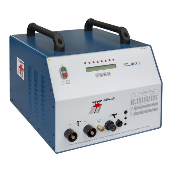
Construction of the BMH-22i stud welder The BMH-22i stud welder has a handy, compact and robust design. The carrying handles on the top of the housing allow easy transport so that the stud welder can be used at different work places. -
Page 18: Technical Data
Designation BMH-22i Drawn arc stud welding (DS) Welding process Electrode welding rectifier SOYER threaded studs, DIN EN ISO 13918 from Welding range M8 – M24 RD (MR) or Ø 8 – 22 mm Material Steel, stainless steel and heat-resistant steel... -
Page 19: Installation Of Stud Welder
• Ensure sufficient ventilation of the working room when operating the welding system. NOTE The housing of BMH-22i stud welder corresponds to safety class IP 21. Please observe that this system of protection is not suitable for being operated or transported in the rain. -
Page 20: Start-Up
BMH-22i 5 Start-up Front and rear view Front view of BMH-22i stud welder • OFF switch to turn the stud welder off • Signal lamp (operation mode) • ON switch to turn the stud welder on • LCD display • LED displays for function control •... - Page 21 BMH-22i Rear view of BMH-22i stud welder 9-pole connection for external program selection (option) This interface serves to be connected with an external control system for controlling the welding parameters. Danger sign 15-pole connecting socket / Feeder interface (option) The feeder interface serves to connect the feeder control to the stud welding device.
-
Page 22: Operating Elements
BMH-22i 5.1.1 Operating elements • On/Off switch Turn on/off switch to the "I" position to switch the stud welder on. The signal lamp shows that the stud welder is operative. Turn on/off switch to the "0"position to switch the stud welder off. - Page 23 BMH-22i Explanation of displayed operation modes: • MODE Operation mode set. It is possible to set six different operation modes: 1- OP = Operating state which must be set for normal welding operation. 2- PRE = Preweld current test 3- LIFT = Lift test...
-
Page 24: Symbols
BMH-22i 5.1.4 Symbols Symbol Designation Function On/Off switch for turning the stud welder on and Electrical energy off. LED lights up when earth terminal of stud welder LED "Stud is connected and stud touches the workpiece. on Workpiece" LED lights up when pressing release switch of LED “Release"... -
Page 25: Preparation For Start-Up
BMH-22i Preparation for start-up Connect the stud welding gun and earth cables to the stud welder prior to start-up. 5.2.1 Earth connection • Attach earth cable to earth cable connectors and lock by turning to the right until stop. • Attach earth clamps to workpiece. -
Page 26: Connection Of Stud Welding Gun
BMH-22i Examples for various earth connections and possible effects: Balanced earth connection Ideal condition: The stud is located in the centre of both earth connections. Unbalanced earth connection Arc is deflected to the side where there is less current density. -
Page 27: Power Supply
BMH-22i 5.2.4 Power supply • Compare the power data (supply voltage / current consumption) on the type plate with the data (supply voltage / fuse protection) of your power supply network. Always ensure the correct supply voltage in accordance with the type plate. Never connect the stud welding device to a power supply network with incorrect supply voltage. - Page 28 BMH-22i 5.3.2.1 Operation mode "OP" (operating state) The operation mode "OP" allows normal welding operation with the welding parameters set. • Use the function key "arrow up" or "arrow down" (1 or 2) to set operation mode "OP". 5.3.2.2 Operation mode "PRE" (preweld current test) The adjustment "PRE"...
- Page 29 BMH-22i • Insert a stud into the gun or welding head. • Check the immersion depth of the stud and/or set it according to the operating instructions of the welding gun or welding head. CAUTION Ensure once again that the operation mode is set to "LIFT" and comply with the safety instructions.
- Page 30 BMH-22i 5.3.2.4 Operation mode "GAS" (gas test) This operation mode checks whether the shielding gas flows through the gas shroud of the welding gun or welding head. As long as a triggering signal is there, shielding gas flows out of the gas shroud on the welding gun or welding head.
-
Page 31: Special Functions
• Use the function key "arrow up" or "arrow down" (1 or 2) to set the desired current intensity. Special functions With the stud welder BMH-22i you can call additional special functions: Start dealing with the special functions when you are familiar with the basic functions of the stud welder. -
Page 32: Special Function "Erasing The Working Storage
BMH-22i After this, the stud welder can be restarted. 5.4.1 Special function "Erasing the working storage" This special function serves as "RESET function" e.g. for eliminating troubles or starting the stud welder the first time. NOTE The entire data of your working storage are erased when using this function. Your personal settings such as welding parameters, language selection and other special functions are reset to the basic setting. -
Page 33: Special Function "Setting The Type Of Feeder And Its Functions" (Option)
BMH-22i • Follow the instructions on the display. 5.4.4 Special function "Setting the type of feeder and its functions" (option) With automatic operation, this special function serves to adapt the control to the feeder (parameter 1- 4, only with BMK feeder). The type of feeder connected can be set by means of parameter 5. -
Page 34: Special Function "Setting The Feeder Operation" (Option)
BMH-22i Explanation of parameters • Piston This parameter serves to adjust the post-blow time of the stud feed blow air beyond the standard measure when the pushing piston in the welding gun/welding head has moved forward to press the stud out of the stud holder. A longer time setting is required when welding e.g. above the head to achieve a trouble-free stud reload. - Page 35 BMH-22i Display when setting feeder type "BMK" By using the function keys "arrow left" or "arrow right" you can move the slider in the feeder’s stud escapement to the left or right end position and thereby check the setting. During this process, the operating states of possible existing sensors are displayed as "on"...
-
Page 36: Operation
BMH-22i 6 Operation NOTE The applicable accident prevention and safety regulations have to be complied with when operating the stud welder. 6.1.1 Setting welding parameters for standard welding operation • Turn on/off switch to the "I" position to switch the stud welder on. - Page 37 BMH-22i The setting values for the most important stud dimensions are represented in tabular form on the front panel of the stud welder. 6.1.1.3 MCT (main current time in milliseconds) • Select function "MCT" by pressing either function key "arrow left" (3) or "arrow right" (4).
- Page 38 BMH-22i 6.1.1.6 RLT (reload time in milliseconds) The reload time is the period of time the blow air valve requires for transporting the stud from the universal feeder to the welding gun or welding head. The longer the blow air hose is, the higher you have to set the reload time correspondingly.
-
Page 39: Welding Parameters For Welding Operation
The parameters depend on the size of the studs and the material properties. The values indicated in the tables are standard values which are exclusively valid for studs supplied by SOYER. They may vary depending on the type of workpiece, the workpiece thickness, the surface condition of the workpiece and on environmental conditions (e.g. -
Page 40: Welding Operation With Shielding Gas
BMH-22i Important information for standard welding operation (stud welding) The measures mentioned in the "Start-up of stud welder" chapter have already been performed. NOTE The applicable accident prevention and safety regulations must be complied with when operating the stud welder. -
Page 41: Preparation Of Gas Supply
BMH-22i 6.2.1 Preparation of gas supply Example for gas supply. Deviations are possible depending on the manufacturer 1 Gas cylinder 5 Shut-off valve 2 Hand wheel (left = open, right = closed) 6 Gas supply hose 3 Manometer for indicating the gas cylinder’s... -
Page 42: Welding Operation With Ceramic Ferrules
Illustration: Stud welding with ceramic ferrule Welding operation with ceramic ferrules is only possible when using SOYER drawn arc welding studs, types PD, MD, RD, UD and SD, similar to DIN EN ISO 13 918. 6.3.1 Instructions for welding with ceramic ferrules •... - Page 43 BMH-22i • Place ceramic ferrule on ceramic ferrule holder. • Position the welding gun in such a way that the centre of the stud points exactly toward the marked welding point. • Make sure that the gun does not tilt, i.e. that the ceramic ferrule is positioned evenly on the workpiece.
-
Page 44: Quality Control (Stud Welding)
7 Quality control (stud welding) General Provided that the SOYER stud welding system is properly used and the materials are appropriately selected, the strength of the welding joint (welding zone) will always be stronger than that of the stud or base material. -
Page 45: Visual Inspection
BMH-22i 7.3.2 Visual inspection The visual inspection serves as a rough check for major defects. The uniformity of the weld is assessed. Good weld quality. Optimum setting. Regular, bright and complete collar. Poor weld quality e.g. caused by excessive welding energy or insufficient plunge or lift. -
Page 46: Bend Test
Note Numerous special accessories are optionally available for perfectly testing stud welded joints: BP-1 SOYER Bend Testing Device for non-destructive stud testing to support quality assurance procedures DMS-1 SOYER Torque Wrench for non-destructive stud testing to support quality assurance procedures For further information, please contact our parent company or the customer service responsible for your area or visit our website at www.soyer.de. -
Page 47: Maintenance
However, please observe the manufacturer’s specifications on the detergent you intend to use. Replacement of components Defective components may only be replaced by trained SOYER servicemen. Perfect function of your stud welder can only be guaranteed when original SOYER spare parts are used. -
Page 48: Troubleshooting
The following list of errors, their causes and remedies is designed to help you eliminate any trouble immediately on the spot. If it is difficult or impossible to eliminate the trouble, please contact the SOYER customer service responsible for your area or Heinz Soyer Bolzenschweißtechnik GmbH. DANGER... -
Page 49: Malfunctions
Set gas flow rate to 4-5 l/min by means of the control cock. Solenoid valve in stud welder is soiled or defective. Deaerate solenoid valve, clean it and/or have it replaced by SOYER customer service. Stud does not lift, neither Height of lift is not correctly set. - Page 50 Control of stud welder or welding gun is defective. (Stud does not lift, workpiece” lights up. even though height of lift is correctly set). Contact SOYER customer service. Stud lifts, preweld current Operating mode is set to position "PRE".
- Page 51 BMH-22i Welding gun in tilted position. Ensure that all three gun legs are simultaneously and evenly positioned on the workpiece. Lift not correctly set. Set lift correctly. Stud welder switches off. Stud lift not correctly set. Set stud lift in accordance with the operating instructions of the welding gun.
-
Page 52: Transport And Storage
The stud welder is robustly designed and has a two-piece metal housing with front and rear panel. Owing to electronic components it should be ensured, however, that transport is free from vibrations. The BMH-22i stud welder has two carrying handles on its top for easy transport and mobile use within short distances. -
Page 53: List Of Standards And Guidelines
BMH-22i List of standards and guidelines • 2014/35/EU Directive on Low Voltage • 2014/30/EU Directive on Electromagnetic Compatibility • EN 60974–1 Arc welding equipment - welding current sources • EN 60974–10 Arc welding equipment - EMC requirements • DVS Information Sheet 0901 Arc stud welding of metallic materials •... - Page 55 Appendix A / Adjustment of drawn arc and short-cycle drawn arc stud welding guns Appendix A / Drawn arc stud welding General............................2 Adjustment of stud welding gun....................3 Stud holder for drawn arc operation..................3 Installation of stud holder into stud welding gun ..............4 Adjusting the depth of immersion..................5 Height of lift ........................7 2.4.1...
-
Page 56: General
The stud welding guns were equipped with different welding cable connectors depending on the welding range. Adapter cables (not included in delivery) enable you to operate the stud welding guns with SOYER stud welders having different welding cable connections. Order list for adapter cables / connectors... -
Page 57: Adjustment Of Stud Welding Gun
Appendix A / Adjustment of drawn arc and short-cycle drawn arc stud welding guns 2 Adjustment of stud welding gun Stud holder for drawn arc operation The PH-2L, PH-4L and PH-5L stud welding guns can be equipped with a stud holder for drawn arc operation when studs with a diameter of more than 6 mm are to be welded. -
Page 58: Installation Of Stud Holder Into Stud Welding Gun
Appendix A / Adjustment of short-cycle drawn arc stud welding guns Installation of stud holder into stud welding gun DANGER Switch off the welding equipment before adjusting it (mains switch must be in "OFF” position). The stud holder suitable for the corresponding stud diameter is installed as follows: Illustration: PH-5L stud welding gun 1 Support leg 2 Allen screws... -
Page 59: Adjusting The Depth Of Immersion
Appendix A / Adjustment of drawn arc and short-cycle drawn arc stud welding guns Adjusting the depth of immersion DANGER Switch off stud welder to adjust the depth of immersion. The stud must be firmly inserted into the stud holder until stop. ... - Page 60 Appendix A / Adjustment of short-cycle drawn arc stud welding guns How to adjust the depth of immersion: • Insert the relevant stud (3) into stud holder until stop. • Loosen both Allen screws (item 2, chapter 2.2). • Move support legs (item 1, chapter 2.2) until the required depth of immersion is obtained.
-
Page 61: Height Of Lift
Appendix A / Adjustment of drawn arc and short-cycle drawn arc stud welding guns Height of lift The height of lift is the distance the stud is lifted from the workpiece during the welding process. This distance is required for igniting the arc. Determination and adjustment of the lift is the same for welding with both support tube and ceramic ferrules. -
Page 62: Adjusting The Height Of Lift
Appendix A / Adjustment of short-cycle drawn arc stud welding guns 2.4.2 Adjusting the height of lift The height of lift can be adjusted by turning the adjusting cap (2) at the welding gun’s back to the left or to the right. Turning the adjusting cap (2) to the left increases the height of lift, turning to the right decreases the height of lift. -
Page 63: Immersion Speed
Appendix A / Adjustment of drawn arc and short-cycle drawn arc stud welding guns Immersion speed 2.5.1 Adjusting the speed of immersion for PH-4L and PH-5L The immersion speed or its damping depends on the stud diameter. Studs with up to 10 mm in diameter do not require any damping (turn adjusting screw (1) to the left till it stops). -
Page 64: Adjusting The Speed Of Immersion (Damping) For Ph-2L
Appendix A / Adjustment of short-cycle drawn arc stud welding guns 2.5.2 Adjusting the speed of immersion (damping) for PH-2L The PH-2L stud welding gun can only be set to “Damping ON” or “Damping OFF”. An infinite adjustment of the immersion speed is not possible. 1 Setting screw 2 Securing screw 3 Hexagon screwdriver 4mm... -
Page 65: Start-Up
Appendix A / Adjustment of drawn arc and short-cycle drawn arc stud welding guns 3 Start-up Total view The illustration below shows the standard stud welding gun for drawn arc operation. A large range of equipment is available. 1 Ceramic ferrule 2 Stud holder 3 Support retainer 4 Adjusting cap... -
Page 66: Operation
Appendix A / Adjustment of short-cycle drawn arc stud welding guns Operation • Connect stud welder to earth. • Adjust stud welding gun as described in Appendix A, chapter 2. • Connect stud welder to mains supply. • Adjust parameters at stud welder according to welding studs to be used. •... -
Page 67: Spare Parts / Wear Parts
Appendix A / Adjustment of drawn arc and short-cycle drawn arc stud welding guns 4 Spare parts / Wear parts Spare parts list for PH-2L, 4L, 5L stud holders and accessories View Description Dimensions / Type Order No. Drawn arc and short-cycle F01190 drawn arc stud holder F01191... - Page 68 Appendix A / Adjustment of short-cycle drawn arc stud welding guns View Description Dimensions / Type Order No. Flat-head screw M6 x 25 M01439 Two pieces are required for mounting the foot plate to the support legs Conical socket M8 Ø = 9.6mm M01440 Two pieces are required for mounting the foot plate to...
- Page 69 Appendix A / Adjustment of drawn arc and short-cycle drawn arc stud welding guns View Description Dimensions / Type Order No. Earth cable with clamp for 50mm² F01666/FA BMK-16i, LC, W and BMH- 16 SV Earth cable with clamp for 95mm²...
-
Page 70: Spare Parts For Ph-2L
Appendix A / Adjustment of short-cycle drawn arc stud welding guns 5 Spare parts for PH-2L Spare parts list for PH-2L stud welding gun in preparation Appendix A /16... -
Page 71: Spare Parts For Ph-4L And Ph-5L
Appendix A / Adjustment of drawn arc and short-cycle drawn arc stud welding guns 6 Spare parts for PH-4L and PH-5L Spare parts list for PH-4L and PH-5L stud welding guns Item Qty. Designation Order No. Order No. PH-4L PH-5L PH-5L stud welding gun, complete P02250 P02260... - Page 72 Flat-head screw M4 x 12 M03634 Gun handle, left side F04184 Gun handle, right side F04185 Strain relief, part 2 F04186 Gun label, Soyer logo M03615 Bush for press button F04187 Cover disk for press button F04188 Press button, 1-pole E02103...
-
Page 73: Exploded View Of Ph-5L Stud Welding Gun
Appendix A / Adjustment of drawn arc and short-cycle drawn arc stud welding guns Exploded view of PH-5L stud welding gun Appendix A /19... - Page 74 Heinz Soyer Bolzenschweißtechnik GmbH Etterschlag Inninger Straße 14 D-82237 Wörthsee Tel.: ++49-(0) 81 53 / 8 85-0 Fax: ++49-(0) 81 53 / 80 30 Internet: www.soyer.de E-Mail: info@soyer.de...
Need help?
Do you have a question about the BMH-22i and is the answer not in the manual?
Questions and answers