
Related Manuals for Soyer BMH-30i


Summary of Contents for Soyer BMH-30i
- Page 1 BMH-30i Operating Instructions Stud Welder GB: English Version Read these operating instructions before starting any work! Doc.ID: P00234 Date of issue: 08.2015 www.soyer.de...
- Page 3 Order No. Code designation Note P01350 BMH-30i Mains voltage 3 x 400 V Heinz Soyer Bolzenschweißtechnik GmbH www.soyer.de Inninger Straße 14 | 82237 Wörthsee | Tel.: +49 8153 8850 | Fax: +49 8153 8030 | E-mail: info@soyer.de |...
- Page 4 ® Congratulations on purchasing the BMH-30i SOYER stud welder. ® You have made an excellent choice. Your BMH-30i SOYER stud welder was specially developed for ® the high-speed fastening of SOYER weld studs in compliance with DIN EN ISO 13918 on metallic, weldable workpieces.
- Page 5 Heinz Soyer Bolzenschweißtechnik GmbH Inninger Straße 14 82237 Wörthsee CE Declaration of Conformity We herewith declare that the machine described in the following and the version available on the market correspond in design and construction to the safety and health requirements of the listed guidelines and standards.
-
Page 6: Table Of Contents
Drawn arc stud welding technology using shielding gas ..........14 3.1.2 Drawn arc stud welding technology using ceramic ferrules ..........15 Technical data ........................16 Interfaces BMH-30i ......................17 3.3.1 CNC interface ........................17 3.3.2 RS 232-interface (SO-250 option) ................... 17 3.3.3... - Page 7 5.4.1 Special function "Deleting the main memory" ..............33 Special functions – Extended submenu ................34 5.4.2 5.4.3 Special function "Display of operating counter" ............... 34 5.4.4 Special function "Setting the type of feeder and its functions" ........35 5.4.5 Special function "Setting the language"...
-
Page 8: Safety Instructions
1 Safety instructions These safety precautions are for your safety. General safety instructions Take part in a training programme. Read and follow all safety precautions listed below and all chapters of this manual before starting to weld. Non-compliance with the safety precautions can result in personal injuries or death. - Page 9 Fumes and gases can cause damage to your health Fumes and suspended/floating particles may be generated during welding. Beware of fumes detrimental to health, particularly when using surface treated materials. Please also observe the safety regulations applicable for your country. Do not inhale fumes and gases.
-
Page 10: Description Of Reference Signs In The Operating Instructions
Description of reference signs in the operating instructions The non-observance of safety instructions such as pictographs and warning words can cause damage to persons. The safety instructions of this operating manual describe the following: Safety instructions Danger! Immediate hazards which could result in serious personal injuries or loss of life. -
Page 11: Staff Qualification And Training
Roll up the cables without buckling them. Prevent the welding equipment being operated by unauthorized personnel. Check welding cables and connections of the welding equipment for damage such as burn-off, ® mechanical wear etc. and have damaged parts replaced by the SOYER customer service. -
Page 12: General
2 General The following should be principally observed... With the BMH-30i stud welder you have purchased a product which is state-of-the-art technology fully complies with the current safety requirements and ensures high performance. Before installing the welding equipment, please observe the following: ... -
Page 13: Information On The Operating Instructions
All obligations of Heinz Soyer Bolzenschweißtechnik GmbH result from the respective contract of purchase. This contract also contains the complete and universally valid warranties. These contractual warranty terms are neither extended nor restricted by the implementation of these operating instructions. -
Page 14: Description Of Stud Welding Equipment
● Manual electric welding (electrode welding) ● TIG welding The PH-5L stud welding gun with control cable is the standard gun to be connected to the BMH-30i stud welder. This operating manual exclusively describes the BMH-30i stud welder. Information regarding the stud welding guns to be used as well as their setting can be obtained from the respective operating manuals of the stud welding guns. -
Page 15: Drawn Arc Stud Welding Technology Using Ceramic Ferrules
3.1.2 Drawn arc stud welding technology using ceramic ferrules The ceramic ferrule fulfils the following functions: • It centres the electric arc. • It protects the welding point from the atmosphere. • It ensures the exact formation of the welding bead. •... -
Page 16: Technical Data
Technical data Designation BMH-30i Drawn arc stud welding (DA) Welding process Electrode welding rectifier ® SOYER threaded studs, DIN EN ISO 13918 from Welding range M8 - M24 or Ø 6 - 25 mm Steel, stainless steel and heat-resistant steel (aluminium... -
Page 17: Interfaces Bmh-30I
3.3.3 Feeder interface (optional) The feeder interface serves as the control and communication of our systems for the external stud ® feed e.g. by means of an UVR-300 SOYER universal feeder. -
Page 18: Pg.select
3.3.4 PG.Select Communication interface for the P3-Select/S gun distribution system. This interface serves for the automatic selection of programs (for further information, please refer to the operating instructions of the P3-Select gun distribution system). -
Page 19: Installation Of Welding Equipment
4 Installation of welding equipment The BMH-30i stud welding equipment is equipped with four lifting lugs on its top and can be easily transported by means of four high-quality castors (two fixed castors and two guide castors with brake). DANGER! - Page 20 When welding with shielding gas, make sure the gas cylinder is installed safely in its approved, accident-proof installation device. NOTE The housing of BMH-30i stud welder corresponds to safety class IP21. Please observe that this system of protection is not suitable for being operated or transported in the rain.
-
Page 21: Preparation Of Gas Supply
Preparation of gas supply Gas supply must be provided before welding with shielding gas. The gas connection at the rear side of the stud welding equipment serves to supply the stud welding equipment with gas by means of a pressure reducer (pressure reducing valve not included in delivery). The admissible gas flow value ranges from between 4 to 5 l/min. -
Page 22: Start-Up
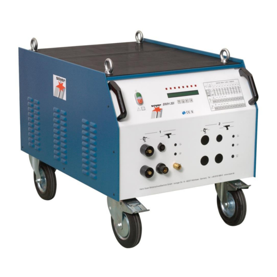
5 Start-up Front- and rear view Front view BMH-30i OFF switch (to switch stud welder off) Signal lamp (operating mode display) ON switch (to switch stud welder on) LCD display LED displays for function control Function keys for setting the welding parameters Air function "forward"... - Page 23 Rear view BMH-30i 14 : 15-pole connecting socket for controlling the feeder 15 : 9-pole connecting socket for controlling the stud welder via a CNC interface 16 : 9-pin connector, interface RS 232 17 : Danger sign 18 : Type plate...
-
Page 24: Operating Elements
Press the "OFF" switch (item 1, chapter 5.1) to turn the stud welding equipment off. Function keys for setting the welding parameters (item 6, chapter 5.1) The BMH-30i stud welder has four function keys on the front panel for setting the welding parameters: Function key “Arrow up”... -
Page 25: Display Elements (Led Displays)
5.1.2 Display elements (LED displays) Description 5.1 LED "SOW" LED lights up as soon as the stud touches the workpiece provided the workpiece is connected to the earth pole of the stud welding equipment. 5.2 LED "Release" LED lights up when pressing the trigger switch of the gun or when the start signal at the external interface has been activated. - Page 26 Setting options for welding operation (OP) Parameter Description Range Number of programs available 1 - 30 Main current 360 - 3000 A (in increments of Main current time 3 - 2000 ms Preweld current time 5 - 999 ms Gas preflow time 0 - 9900 ms (in increments of Period of time during which the shielding gas valve 100)
-
Page 27: Description Of Symbols
5.1.4 Description of symbols Symbol Designation Function Electrical energy ON/OFF key to turn the stud welding equipment on or off. LED "Stud on LED lights up when earth terminal of stud welding equipment Workpiece" is connected and stud touches the workpiece. LED lights up when pressing release button of welding gun or LED "Release"... - Page 28 Ensure optimum contact with workpiece. Owing to the high welding current, an unbalanced current distribution may cause a magnetic blow effect on the arc, i.e. the arc for welding the stud is asymmetrical. This is shown by an irregular course of the welding bead on the side of the stud.
-
Page 29: Connection Of Stud Welding Gun
5.2.2 Connection of stud welding gun Connect welding cable of welding gun to the relevant socket (item 10, chapter 5.1) and lock it by turning to the right until stop. Insert control cable into control cable connection (item 9, chapter 5.1) and tighten with sleeve nut. -
Page 30: Operating Mode "Op
The stud welding equipment is locked during the self test and it is impossible to operate it. After the self test has been carried out successfully, the welding equipment automatically sets the parameters which were last set. When the main switch is kept pressed, an input network check is carried out with those stud welder types equipped with a 3-phase protection module. -
Page 31: Operating Mode "Lift" (Lift Test)
5.3.3 Operating mode "LIFT" (lift test) This operation mode enables you to adjust and check the lift of the gun or welding head. Use the function key “Arrow up" or "Arrow down" to set operation mode "LIFT". Insert a stud into the welding gun or welding head. ... -
Page 32: Operating Mode "Meas" (Measuring) Option
This operating mode checks whether the shielding gas flows through the gas shroud of the welding gun or welding head. As long as there is a triggering signal, shielding gas flows out of the gas shroud on the welding gun or welding head. This enables you to rinse the gas supply lines with shielding gas before starting to weld. -
Page 33: Tig Welding
Setting range: 120 -300 Special functions – Submenus With the BMH-30i stud welding equipment you can call up additional special functions: The stud welding equipment must be switched off when calling up special functions. In order to call up the respective special function you have to press certain function key combinations and keep them pressed when starting the stud welding equipment. -
Page 34: Special Functions - Extended Submenu
Special functions – Extended submenu 5.4.2 This submenu allows various parameters to be adapted. To call up this special function, the following steps are necessary: Simultaneously press the “Down arrow”, “Up arrow” and “Left arrow” function keys and keep them pressed. -
Page 35: Special Function "Setting The Type Of Feeder And Its Functions
5.4.4 Special function "Setting the type of feeder and its functions" With automatic operation, this special function serves to adapt the control to the feeder. To call up this special function, please proceed as follows: Simultaneously press "Arrow right" and "Arrow left" keys and keep them pressed. ... -
Page 36: Special Function "Setting The Language
Explanation of parameters Parameter Description Range Default value 0 – 2000 ms Piston This parameter sets the after-running time of the stud feed blow air for the pushing piston in the welding gun/welding head to press the stud out of the stud chuck. -
Page 37: Special Function "Protocol/Log" (Option)
Serves to switch the measurement data transfer on or off via the RS 232 interface. The measurement data is transferred automatically after every weld. To further ® process the data, you need an external PC with the necessary SOYER software installed. -
Page 38: Welding Parameters
The welding parameters were determined with the BMH-30i stud welding equipment and the PH-5L ® stud welding gun. A steel plate with a thickness of 10 mm served as base metal for SOYER weld studs as per DIN EN ISO 13918. -
Page 39: Operation
6 Operation Brief description This section is designed to provide you with a quick start into the welding operation. For detailed information, please refer to chapter 6.2. NOTE The applicable accident prevention and safety regulations in chapter 1 have to be complied with when operating the stud welder. NOTE The welding areas must be metallically bright. -
Page 40: Adjustment Of Stud Welding Gun
Adjustment of stud welding gun 6.2.1 Stud chuck for drawn arc operation The PH-2L, PH-4L and PH-5L stud welding guns can be equipped with a stud chuck for drawn arc operation when studs with a diameter of more than 6 mm are to be welded. The stud chuck is directly screwed on the retaining screw. -
Page 41: Installation Of Stud Chuck Into Stud Welding Gun
6.2.2 Installation of stud chuck into stud welding gun DANGER Switch off the welding equipment before adjusting it (mains switch must be in "OFF” position). The stud chuck suitable for the corresponding stud diameter is installed as follows: Illustration: PH-5L stud welding gun 1 Support leg 2 Allen screws •... -
Page 42: Adjusting The Depth Of Immersion
6.2.3 Adjusting the depth of immersion DANGER Switch off stud welding equipment to adjust the depth of immersion. The stud must be firmly inserted into the stud chuck until stop. The depth of immersion is the distance the stud projects over the end of the ceramic ferrule, the gas shroud or the support tube. - Page 43 How to adjust the depth of immersion: • Insert the relevant stud (3) into stud chuck until stop. • Loosen both Allen screws (item 2, chapter 6.2.2). • Move support legs (item 1, chapter 6.2.2) until the required depth of immersion is obtained. •...
-
Page 44: Height Of Lift
6.2.4 Height of lift The height of lift is the distance the stud is lifted from the workpiece during the welding process. This distance is required for igniting the arc. Determination and adjustment of the lift is the same for welding with both support tube and ceramic ferrules. -
Page 45: Adjusting The Height Of Lift
6.2.5 Adjusting the height of lift The height of lift can be adjusted by turning the adjusting cap (2) at the welding gun’s back to the left or to the right. Turning the adjusting cap (2) to the left increases the height of lift, turning to the right decreases the height of lift. -
Page 46: Immersion Speed
6.2.7 Immersion speed Adjusting the speed of immersion for PH-4L and PH-5L The immersion speed or its damping depends on the stud diameter. Studs with up to 10 mm in diameter do not require any damping (turn adjusting screw (1) to the left till it stops). -
Page 47: Stud Welding With Shielding Gas
Stud welding with shielding gas NOTE The applicable accident prevention and safety regulations in chapter 1 have to be complied with when operating the stud welding equipment. Set the parameters required for your welding task. 1 Foot plate 2 Gas shroud 3 Welding stud Fig. -
Page 48: Stud Welding With Ceramic Ferrules
Stud welding with ceramic ferrules Foot plate Ceramic ferrule Weld stud Fig. Stud welding with ceramic ferrule Set the parameters required for your welding task. Only use ceramic ferrules which are absolutely dry and do not show any flaws. ... -
Page 49: Welding Operation With Quality Control "Meas" (Option)
Only use original parts. ® No warranty is provided when non-SOYER welding studs are used. Press the trigger of the gun or welding head or give a triggering signal via the CNC interface. The stud is lifted off the workpiece and a test weld is carried out. - Page 50 The saved results of the five test welds are averaged and transferred as reference values in the set program when exiting the operating mode "MEAS". The acquisition of reference values can be repeated at any time. The existing values are overwritten. Select the admissible deviation of the quality control Value TL = Tolerance 0 = Quality control off.
-
Page 51: Quality Control (Stud Welding)
7 Quality control (stud welding) General instructions ® Provided the SOYER welding equipment is correctly used and the materials are appropriately selected, the strength of the welding joint (welding zone) will always be stronger than that of the stud or base material. -
Page 52: Bend Test
7.2.3 Bend test The bend test is a simple work test which serves to roughly check the setting values selected. The welding zone is subjected to undefined tension, pressure and bending. A minimum of 3 studs are welded and bent by means of a tube slipped over the stud. The test is successful when no superficial fissure or fracture is detected in the welding zone. -
Page 53: Maintenance
SOYER spare parts are used. CAUTION Disconnect the mains cable from the mains supply before replacing any components. ® Electric and electronic components may only be replaced by the SOYER customer service or by trained and appropriately qualified personnel. - Page 54 CAUTION Should it become necessary to replace fuses, only use fuses with the specified electrical values. Oversized fuses could either cause defects to the electrical system or a fire. DANGER Disconnect the mains plug from the mains supply when replacing fuses.
-
Page 55: Troubleshooting
The following list of errors, their causes and remedies is designed to help you eliminate any trouble ® immediately on the spot. If you cannot eliminate the trouble, please contact the SOYER customer service responsible for your area or Heinz Soyer Bolzenschweißtechnik GmbH. -
Page 56: Malfunctions
Set gas flow rate to 4 - 5 l/min by means of the regulating valve. Solenoid valve in welding equipment is soiled or defective. Deaerate solenoid valve, clean it and/or have it replaced by SOYER ® customer service. - Page 57 You have used low-quality studs with inaccurate dimensions or poor surface finish. ® Only use SOYER welding studs as per DIN EN ISO 13 918. Welding time and/or gas flow incorrectly set. Readjust welding time and/or gas flow.
- Page 58 Welding equipment Stud lift not correctly set. Set stud lift in accordance with the operating instructions of the welding switches off. gun. Switch welding equipment on. You have pulled the welding gun off the workpiece while main current has been flowing.
-
Page 59: Transport And Storage
Owing to electronic components it should be ensured, however, that transport is free from vibrations. The BMH-30i stud welding equipment is equipped with four lifting lugs on its top and can be easily transported by means of four high-quality castors (two fixed castors and two guide castors with brake). -
Page 60: List Of Standards And Guidelines
12 List of standards and guidelines • 2014/35/EU Directive on Low Voltage • 2014/30/EU Directive on Electromagnetic Compatibility • EN 60974–1 Arc welding equipment - welding current sources • EN 60974–10 Arc welding equipment - EMC requirements • DVS Information Sheet 0901 Arc stud welding of metallic materials •... - Page 62 Heinz Soyer Bolzenschweißtechnik GmbH www.soyer.de Inninger Straße 14 | 82237 Wörthsee | Tel.: +49 8153 8850 | Fax: +49 8153 8030 | E-mail: info@soyer.de |...
Need help?
Do you have a question about the BMH-30i and is the answer not in the manual?
Questions and answers