Table of Contents
Advertisement
Advertisement
Table of Contents

Related Manuals for Soyer BMS-10N


Summary of Contents for Soyer BMS-10N
- Page 1 Operating Instructions Stud Welder BMS-10N BMS-10NV...
-
Page 2: Operating Instructions
Operating Instructions Stud Welder BMS-10N BMS-10NV Serial number* Stud welder BMS-10N 148- Serial number* Stud welder BMS-10NV 148- * Please mark your type of stud welder with a cross and enter the serial number, so that these data are available if you need service support. - Page 3 The data in this documenta- tion, however, have been verified regularly and necessary corrections will be incorporated in future impressions. We appreciate any suggestions for improvement. Heinz Soyer Bolzenschweißtechnik GmbH 1995 · All rights reserved Date of issue: 01.12.1995 Subject to technical changes...
- Page 4 EC Conformity Declaration in compliance with EC Directive on Machinery 89/392/EEC, appendix IIA Producer: Heinz Soyer Bolzenschweißtechnik GmbH Etterschlag Inninger Straße 14 D-82237 Wörthsee Declaration: We herewith declare that the machines described in the following and the versions available on the market correspond in their design and construction to the fundamental safety and health requirements stipulated by EC Directive on Machinery.
-
Page 8: Table Of Contents
Contents Contents General ___________________________________________________________________________ 1-1 The following should be principally observed ... ____________________________________________ 1-1 Application __________________________________________________________________________ 1-2 Information on the product _____________________________________________________________ 1-2 Type plate ___________________________________________________________________________ 1-2 Information on the documentation _______________________________________________________ 1-3 1.5.1 Chapters of operating instructions _______________________________________________________ 1-3 1.5.2 Information on operating instructions ____________________________________________________ 1-4 1.5.3... - Page 9 Exploded view of BMS-10N stud welder - View A _______________________________________ 13-41 13.5 Spare parts list for BMS-10N stud welder - View B and C ________________________________ 13-42 13.6 Exploded view of BMS-10N stud welder - View B and C _________________________________ 13-43 13.7...
- Page 10 Contents Appendix A/PS-3 - Tip ignition Adjustment of stud welding pistol _________________________________________________ A-1 Adjustment of stud holder ______________________________________________________________ A-1 Installation of stud holder into stud welding pistol __________________________________________ A-2 Adjustment of spring pressure (does not apply to stud welding pistol PS-3) ____________________ A-3 Lift (stud welding pistol PS-3) ___________________________________________________________ A-4 1.4.1 Determining the lift ____________________________________________________________________ A-4...
-
Page 11: General
General General The following should be principally observed ... With this stud welder you have purchased a product which • is state-of-the-art technology • fully complies with the current safety requirements and • enables successful working. Before installing the stud welder, always observe the following: •... -
Page 12: Application
® The SOYER stud welder BMS-10N with tip ignition allows you to weld pins and threaded studs ranging from M3 - M8 or Ø 2 - 8 mm made of steel and stainless steel and M3 - M8 or Ø 2 - 8 mm made of aluminium and brass (depending on requirements), as well as a great number of various welding fasteners (see chapter 2.4, Technical Data). -
Page 13: Information On The Documentation
General Information on the documentation The following operating instructions come with the BMS-10N and BMS-10NV stud welders: • Operating instructions for stud welder BMS-10N, BMS-10NV Order no.: P00191 For repeat-orders please contact: Heinz Soyer Bolzenschweißtechnik GmbH Etterschlag Inninger Straße 14 D-82237 Wörthsee... -
Page 14: Information On Operating Instructions
All obligations of Heinz Soyer Bolzenschweißtechnik GmbH result from the respective contract of purchase which also comprises the complete and generally valid warranties. -
Page 15: Description Of Stud Welder
1 - 3 milliseconds (0.001 - 0.003 sec.). Stud welder set-up The standard pistol to be connected to the stud welders BMS-10N and BMS- 10NV is the stud welding pistol PS-3 with control cable. The stud welders are optionally equipped with an automatic module for the connection of the univer- sal feeder UVR-250S and for fully automatic stud feed. -
Page 16: Dimension
The stud welders BMS-10N and BMS-10NV have a robust, handy and compact design and identical dimensions. Φ BMS-10N HAUPTSCHALTER 0,1 AT 10 AT Heinz Soyer Bolzenschweißtechnik GmbH · Etterschlag · Inninger Str. 14 · 82237 Wörthsee · Tel.: 08153/885-0 Depth 380 mm SZ.0045.E... -
Page 17: Technical Data
Description of stud welder Technical data BMS-10NV Designation BMS-10N Like stud welder BMS-10N Welding range M3 - M8 or Ø 2 - 8 mm with but steel studs up to M10 steel and stainless steel, M3 - M8 or Ø 2 - 8 mm... -
Page 18: Block Diagram
Description of stud welder Block diagram SZ.0067.E... -
Page 19: Interface
Description of stud welder Interface Customer control BMS Stud welder CNC interface Start Release Start With a store programmable control which has a transistor output please observe the polarity! +U external Ready Charge ready Reload time Reload 9 pole D-Sub socket terminal strip Contact load: max. -
Page 20: Alteration Of Supply Voltage
Description of stud welder Alteration of supply voltage Mains supply Mains supply Line Line Binding post black violet black violet orange grey orange grey or white or white Supply 230V Supply 115V SZ.0069.E 2-10... -
Page 21: Safety Instructions
Safety instructions Safety instructions These operating instructions contain basic instructions which have to be complied with during installation and/or operation. It is therefore absolutely necessary that these operating instructions are read by the operator and responsible specialist staff prior to assembly and initiation. They must always be available at the installation site. -
Page 22: Staff Qualification And Training
Safety instructions General instructions are marked with the hand symbol. Staff qualification and training The staff responsible for operation, maintenance, inspection and assembly must have the respective qualification for carrying out these works. Field of responsi- bility, competence and the supervision of staff has to be exactly regulated by the operator. -
Page 23: The Following Should Be Observed Before Starting The System
Safety instructions You are therefore obliged to restrict the dangers to an inevitable degree and to point these dangers out to the operator and other persons involved. MORTAL DANGER Persons with pacemakers must neither operate the stud welder nor stay near it. -
Page 24: Before Starting Welding
Safety instructions Before starting welding ... • Check the state of all cables before starting to weld. • Immediately replace defective cables and cable connections. • Ensure that the air apertures of the housing are not covered. Heat accumu- lation may damage the stud welder. Safety precautions at installation site •... -
Page 25: Safety Instructions For Maintenance, Inspection And Assembly Works
Safety instructions If an accident happens, • switch off the stud welder and disconnect it from the mains supply • call a doctor. 3.10 Safety instructions for maintenance, inspection and assembly works Only carry out maintenance The operator must ensure that all maintenance, inspection and assembly works when stud welder has works are only carried out by authorized and qualified technical personnel. -
Page 26: Stopping The Stud Welder When Welding With Automatic Operation
Safety instructions The tool and gear wagon GW-1 is the optimum solution for installing SOYER stud welders and for properly storing welding pistols, cables, studs, retrofit kits etc. • Make sure stud welder cannot be used by unauthorized personnel. • Turn energy range controller (item 4, chapter 5.1) to the left till stop (smallest energy value). -
Page 27: Installation Of Stud Welder
Installation of the stud welder Installation of the stud welder The sides of the stud welders BMS-10N and BMS-10NV are equipped with two plastic handles. These carrying handles are intended for transport by hand only. Never pull ropes through these handles to lift the system by crane to the installation site. -
Page 28: Initiation
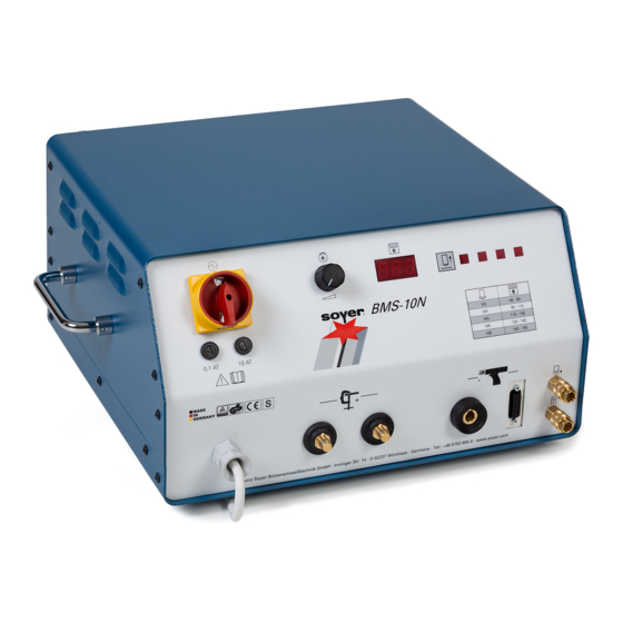
Φ BMS-10N HAUPTSCHALTER 0,1 AT 10 AT Heinz Soyer Bolzenschweißtechnik GmbH · Etterschlag · Inninger Str. 14 · 82237 Wörthsee · Tel.: 08153/885-0 Front view 1 Fuse element with fuse 0.1 AT 8 Air function "forward" (optional) 2 Main switch 9 Air function "backward"... -
Page 29: General Description
All functions can be monitored via clearly visible pilot lamps. The stud welders BMS-10N and BMS-10NV allow you to carry out function tests without welding current for welding pistols and heads (lift test) and to adjust the lift. -
Page 30: Operating Elements
Initiation 5.2.1 Operating elements • Main switch (item 2, chapter 5.1) The main switch is used to switch the stud welder on and off. • Energy range controller (item 4, chapter 5.1) The energy range controller enables infinitely variable energy adjustment for weldable stud diameters. -
Page 31: Fuse
Initiation • Air function "forward" (item 8, chapter 5.1, optional) Connection for welding pistols or heads with automatic stud feed. • Air function "backward" (item 9, chapter 5.1, optional) Connection for welding pistols or heads with automatic stud feed. 5.2.4 Fuse •... -
Page 32: Symbols
Initiation 5.2.5 Symbols Symbol Designation Function Electrical energy Mains switch for switching stud welder on and off. Energy range Potentiometer for controlling the energy control range. Alteration of a Modifying the necessary energy value for quantity the respective stud diameter. Digital measured Digital display of charging voltage in volt. -
Page 33: Preparation For Initiation
Initiation Preparation for initiation MORTAL DANGER Please observe the safety instructions in chapter 3. Do not yet connect the stud welder to the mains supply. Connect the stud welding pistol and earth cables to the stud welder prior to initiation. 5.3.1 Earth connection •... -
Page 34: Connection Of Stud Welding Pistol
Initiation 5.3.2 Connection of stud welding pistol • Connect welding cable of welding pistol or welding head to the welding cable socket (item 11, chapter 5.1) and lock by turning to the right until stop. • Insert control cable into control cable socket (item 10, chapter 5.1) and secure by locking the spring bands. -
Page 35: Welding Parameters
(see DVS Guideline, Part 1, "Quality assurance of stud welding joints"). The welding parameters were determined with the stud welder BMS-10N and the stud welding pistol PS-3 using a lift adjustment of about 2.5 mm. A steel plate with a thickness of 2 mm served as base metal for welding copper-plated capacitor studs made of ST 37-3, as per DIN 32501. -
Page 36: Material Combination
Initiation Material combinations Stud material Base material St 36-2 Ws 1.4303 CuZn 37 AlMg 3 AlSi 12 Al 99,5 (stainless or (Ms63) similar) Steel up to C 0.30 % Steel up to C 0.60 % Steel plate leaded, solder-coated or galvanized max. -
Page 37: Operation
Operation Operation The measures mentioned in the "Initiation of stud welder" chapter have already been performed. The applicable accident prevention and safety regulations in chapter 3 have to be complied with when operating the stud welder. MORTAL DANGER Never touch the stud or stud holder during the welding process. These components are current-carrying ! •... -
Page 38: Quality Control
DIN 4113, part 2). Type and scope of test Provided that the SOYER stud welding system is properly used and the materials are appropriately selected, the strength of the welding joint (welding zone) will always be stronger than that of the stud or base material. The follow- ing tests are carried out in general practice: •... -
Page 39: Simplified Work Test
Quality control The standard work test is restricted to the stud diameter, base material and type of equipment used. It comprises the following tests: • Visual inspection (all samples) • Tensile test (at least 3 samples ) • Bend test (at least 3 samples) In case of doubt, the test scope should be extended in compliance with DVS Guideline 0905, part 2, section 5.1.1. -
Page 40: Bend Test
Quality control If the quantity of defective studs in one random test exceeds the acceptance number specified in DIN 267, part 5, as per AQL 4, it is necessary to find out the reason for the faults. The setting values must be modified and the test repeated. -
Page 41: Maintenance
Replacement of components Defective components may only be replaced by trained SOYER servicemen. Perfect function of your stud welder can only be guaranteed if original SOYER spare parts are used. MORTAL DANGER Ensure that the mains plug has been disconnected and the capacitors are discharged before opening the housing to replace components. -
Page 42: Troubleshooting
The following list of errors, their causes and remedies is designed to help you eliminate any trouble immediately on the spot. If it is difficult or impossible to eliminate the trouble, please contact the SOYER customer service responsible for your area or Heinz Soyer Bolzenschweißtechnik GmbH. - Page 43 Use stud with ignition tip or reduce centre mark Control of stud welder or welding pistol is defective → Contact SOYER customer service Stud is too loose in stud holder → Press stud holder together or tighten it...
- Page 44 Ensure that all 3 pistol legs are simultaneously and evenly positioned on the workpiece Stud welder switches itself off There are mains voltage fluctuations → Connect stud welder directly to the current distribution Control of stud welder, stud welding pistol or welding head is defective → Contact SOYER customer service 9-34...
-
Page 45: Transport And Storage
The stud welder has a robust metal housing. Owing to the electronic compo- nents it should be ensured, however, that transport is free from vibrations. The stud welders BMS-10N and BMS-10NV have two handles at the side for transport and mobile use within short distances. -
Page 46: List Of Standards And Guidelines
List of standards and guidelines List of standards and guidelines • 91/368/EEC EC Directive on Machinery (formerly 89/392 EEC) • 73/23/EEC EC Directive on Low Voltage • 93/31/EEC EC Directive on Electromagnetic (formerly 89/336/EEC) Compatibility • EN 292 - 1 Safety of machinery, basic terms, general principles of construction, basic terminology, systems engineering... -
Page 47: Terms Of Warranty
Terms of warranty Terms of warranty We warrant for this equipment for a period of 6 months in accordance with our conditions of sale and delivery. Any claim to a warranty will be forfeited if damages are caused by improper operation, or if repairs or interferences have been made by unauthorized personnel, or whenever accessories and spare parts have been used which do not match our equipment. -
Page 48: Spare Parts
Spare parts Spare parts 13.1 Spare parts list for BMS-10N stud welder - Overview Item No. Quantity Description Order No. Cap PVC, grey M01251 Fillister head screw M4x10 M01254 U-washer M4, nylon M01251/01 Upper part of housing of BMS-10N F03598... -
Page 49: Exploded View Of Bms-10N Stud Welder - Overview
Spare parts 13.2 Exploded view of BMS-10N stud welder - Overview SZ.0166.X 13-39... -
Page 50: Spare Parts List For Bms-10N Stud Welder - View A
Spare parts 13.3 Spare parts list for BMS-10N stud welder - View A Item No. Quantity Description Order No. Threaded rod M4x140mm M01242 Spring ring M4 M01074 Hexagon nut M4 M01012 Spacing bolt M4x10 M01047 Resistor covering plate F03601 Flat-head screw M4x8 M01351 Distance sleeve Ø7x15... -
Page 51: Exploded View Of Bms-10N Stud Welder - View A
Spare parts 13.4 Exploded view of BMS-10N stud welder - View A SZ.0167.X 13-41... -
Page 52: Spare Parts List For Bms-10N Stud Welder - View B And C
Spare parts 13.5 Spare parts list for BMS-10N stud welder - View B and C Item No. Quantity Description Order No. Cheese-head screw M4x16 M01089 Protective grating E02224 Fan 220/230 volt E02083 Covering plate for fan F03789 Hexagon nut M4... -
Page 53: Exploded View Of Bms-10N Stud Welder - View B And C
Spare parts 13.6 Exploded view of BMS-10N stud welder - View B and C 12 13 20.1 20.2 SZ.0168.X 13-43... -
Page 54: Spare Parts List For Bms-10N Stud Welder - View D And E
Spare parts 13.7 Spare parts list for BMS-10N stud welder - View D and E Item No. Quantity Description Order No. Back panel F03599 Complete pulse counter F03708/FA STA-41 PCB mounting plate F03600 Spring ring M4 M01074 Hexagon nut M4... -
Page 55: Exploded View Of Bms-10N Stud Welder - View D And E
Spare parts 13.8 Exploded view of BMS-10N stud welder - View D and E 14 15 27 28 SZ.0169.X 13-45... -
Page 56: Spare Parts List For Bms-10N Stud Welder - View F
Spare parts 13.9 Spare parts list for BMS-10N stud welder - View F Item No. Quantity Description Order No. Hexagon nut M4 M01012 Spring ring M4 M01074 PC Board STA-31 F03616/FA Distance sleeve 7x1.4x10mm M01261 Distance sleeve 7x1.4x7mm M01260 Mounting plate... -
Page 57: Exploded View Of Bms-10N Stud Welder - View F
Spare parts 13.10 Exploded view of BMS-10N stud welder - View F 34.1 43 44 SZ.0170.X 13-47... - Page 58 Spare parts 13-48...
-
Page 59: Adjustment Of Stud Welding Pistol
Appendix A/PS-3 - Adjustment of stud welding pistols - Capacitor Discharge Adjustment of stud welding pistol Adjustment of stud holder The stud holders of welding pistols PS-1, PS-3K, PS-0K and PS-1K are all of the same type. When using large studs with short type welding pistols PS-0K and PS-1K, however, it is necessary to shorten the stop screw (4) of such welding pistols accordingly. -
Page 60: Installation Of Stud Holder Into Stud Welding Pistol
Appendix A/PS-3 - Adjustment of stud welding pistols - Capacitor Discharge Installation of stud holder into stud welding pistol The illustration below shows how to install the stud holder into the stud welding pistols PS-1, PS-3 and PS-3K. Stud welding pistols PS-0K and PS-1K are provided with a support tube instead of pistol legs (1). -
Page 61: Adjustment Of Spring Pressure (Does Not Apply To Stud Welding Pistol Ps-3)
Appendix A/PS-3 - Adjustment of stud welding pistols - Capacitor Discharge Adjustment of spring pressure (does not apply to stud welding pistol PS-3) When using the stud welding pistol PS-3, adjust the lift instead of the spring pressure. In this case please leave out chapter 1.3 and refer to chapter 1.4 of Appendix A "Adjustment of stud welding pistols - Capacitor Discharge". -
Page 62: Lift (Stud Welding Pistol Ps-3)
Lift is the distance the stud is lifted off the workpiece during the welding process. The adjustment of lift is only possible with stud welding pistol PS-3 combined with stud welder BMS-10N or BMS-10NV. 1.4.1 Determining the lift 1 Spring piston... -
Page 63: Adjusting The Lift
Appendix A/PS-3 - Adjustment of stud welding pistols - Capacitor Discharge 1.4.2 Adjusting the lift 1 Adjusting screw Minimum lift 2 Lifting scale Medium lift 3 Setscrew Maximum lift SZ.0051.E • Loosen setscrew by turning it anticlockwise using Allen key SW 2. •... -
Page 64: Initiation
Appendix A/PS-3 - Initiation - Capacitor Discharge Initiation Total view The illustration below shows stud welding pistol PS-3K. The indicated compo- nents are only slightly different from those of stud welding pistols PS-1, PS-3, PS-0K and PS-1K. • Stud welding pistols PS-0K and PS-1K are provided with support tubes instead of pistol legs (2) •... -
Page 65: Operation
Appendix A/PS-3 - Initiation - Capacitor Discharge Connecting stud welding pistols to stud welder The stud welding pistols are connected to the stud welder by means of pistol and control cables. Operation • Connect stud welder to earth • Connect stud welding pistol as described in chapter 5 •... -
Page 66: Spare Parts
Appendix A/PS-3 - Spare parts - Capacitor Discharge Spare parts Spare parts list for PS-3 stud welding pistol Spare parts list in preparation... - Page 67 Appendix A/PS-3 - Spare parts - Capacitor Discharge Exploded view of PS-3 stud welding pistol Spare parts list in preparation...
- Page 68 Appendix A/PS-3 - Spare parts - Capacitor Discharge A-10...
- Page 69 Heinz Soyer Bolzenschweißtechnik GmbH Etterschlag Inninger Straße 14 D-82237 Wörthsee Tel.: ++49-(0) 81 53 / 8 85-0 Fax: ++49-(0) 81 53 / 80 30 Internet: www.soyer.de www.soyer.com E-Mail: verkauf@soyer.de export@soyer.de...
Need help?
Do you have a question about the BMS-10N and is the answer not in the manual?
Questions and answers