Soyer BMK-12 W Operating Instructions Manual
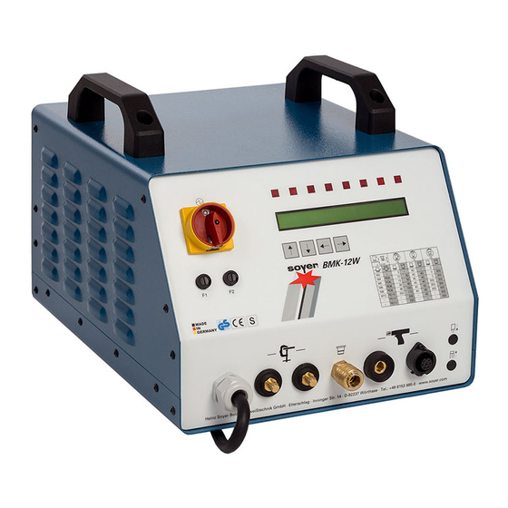
Stud welder
Hide thumbs
Also See for BMK-12 W:
- Quick start manual (34 pages) ,
- Operating instructions manual (68 pages)
Table of Contents
Advertisement
Advertisement
Chapters
Table of Contents

Subscribe to Our Youtube Channel
Related Manuals for Soyer BMK-12 W


Summary of Contents for Soyer BMK-12 W
- Page 1 Operating Instructions BMK-12 W Stud Welder...
- Page 2 BMK-12 W...
-
Page 3: Operating Instructions
Stud Welder Serial number* BMK-12 W stud welder_________________________ Please enter the serial number here, so that the data is immediately available if you need service support. Type table for BMK-12 W stud welder Order no. Code designation Note P01331 BMK-12 W... - Page 4 BMK-12 W...
- Page 5 BMK-12 W We congratulate you on purchasing the BMK-12 W SOYER stud welder. You have made an excellent choice. Your BMK-12 W SOYER stud welder was especially developed for high-speed fastening of SOYER welding studs in compliance with DIN EN ISO 13 918 on metallic workpieces.
- Page 6 BMK-12 W...
- Page 7 BMK-12 W Heinz Soyer Bolzenschweißtechnik GmbH Inninger Straße 14 82237 Wörthsee EC Conformity Declaration in compliance with EC Directive on Machinery 89/392/EEC, appendix II A We herewith declare that the machine described in the following and the version available on the market correspond in its design and construction to the fundamental safety and health requirements stipulated by EC Directive on Machinery.
- Page 8 BMK-12 W...
-
Page 9: Table Of Contents
Drawn arc welding with ceramic ferrules ..............17 Stud welder set-up ....................... 18 View / Dimensions ....................... 18 Technical data......................19 Circuit diagram of BMK-12 W ..................20 2.5.1 Wiring diagram, primary (power circuit, 400 volt standard) ......... 20 2.5.2 Wiring diagram, secondary (welding circuit) .............. - Page 10 Maintenance ...................... 59 Stud welder ........................59 Cleaning........................59 8.2.1 Detergents ........................59 Replacement of components ..................60 Spare parts list for BMK-12 W ................. 61 Spare parts for BMK-12 W................... 61 Troubleshooting ....................62 10.1 Malfunctions......................... 63 Transport and storage..................66...
- Page 11 BMK-12 W List of standards and guidelines ..............67 Appendix A / Adjustment of short-cycle drawn arc welding guns Appendix A...
-
Page 12: General
BMK-12 W 1 General The following should be principally observed ... With this stud welder you have purchased a product which • is state-of-the-art technology • fully complies with the current safety requirements and • enables successful working. Before installing the stud welder, please observe the following: •... -
Page 13: Application
For this purpose, however, special stud holders and ceramic ferrules or gas shrouds are required. With the BMK-12 W SOYER stud welder it is also possible to weld studs of other metallic materials than steel. It is, however, necessary to first carry out experimental welds and to inspect them. -
Page 14: Chapters Of Operating Instructions
BMK-12 W 1.5.1 Chapters of operating instructions The operating instructions describe the start-up and operation of the BMK-12 W stud welder under normal conditions. The present operating instructions of the BMK-12 W stud welder comprise the following chapters in detail: •... -
Page 15: Conduct In The Case Of Malfunctions
Contacts and service address If you have any questions regarding the operation of the stud welding system, retrofits or if you require service, please contact your responsible service office or the following address: Heinz Soyer Bolzenschweißtechnik GmbH Etterschlag Inninger Straße 14 D-82237 Wörthsee... -
Page 16: Description Of Stud Welder
6 mm to prevent pore formation and to optimise the formation of bulges. The standard BMK-12 W stud welder is suitable for operation with shielding gas and ceramic ferrules. A d.c. power supply provides the welding current. The weld duration can be selected. -
Page 17: Drawn Arc Welding With Shielding Gas
Ensure that the surface is electroconductive. Abrase hot galvanized parts. The following welding methods are possible when using the BMK-12 W SOYER short- cycle drawn arc stud welder: • Short-cycle drawn arc stud welding without shielding gas and ceramic ferrules. -
Page 18: Stud Welder Set-Up
The PH-3N stud welding gun with control cable and shielding gas equipment is the standard gun to be connected to the BMK-12 W stud welder. Optionally you may also connect the PH-3L and PK-0K stud welding guns. These operating instructions only refer to the BMK-12 W stud welder. -
Page 19: Technical Data
Technical data Designation BMK-12 W Welding process Drawn arc stud welding (DS) SOYER threaded studs, DIN EN ISO 13918 Welding range from M3 – RD (MR) 12 or 2 – 11mm in diameter Steel, stainless steel and heat-resistant steel (aluminium Material... -
Page 20: Circuit Diagram Of Bmk-12 W
BMK-12 W Circuit diagram of BMK-12 W 2.5.1 Wiring diagram, primary (power circuit, 400 volt standard) main switch welding transfo core 36 primary 400vac 2 turns 400vac 50/60Hz 32AT (F2 front panel) SO1200 holding loop load relay mains (F1 front panel) -
Page 21: Wiring Diagram Of Modules
BMK-12 W 2.5.3 Wiring diagram of modules conection from control transfo °C storage battery 3V only withi SO555 SO555 (F04620/FA) +display (E02998) control board for BMK-12 W J1 J3 J5 J4 (front panel) jumper J1, J3 plugged jumper J5, J4 open... -
Page 22: Wiring Diagram, Primary. Alteration Of Line Voltage
BMK-12 W 2.5.4 Wiring diagram, primary. Alteration of line voltage (OPTION for BMK-12 W universal) DANGER Always disconnect the connecting plug from the mains socket before opening the housing of the stud welder. Only trained and appropriately qualified personnel are allowed to carry out works on the electric power supply and stud welding equipment. -
Page 23: Bmk-12 W Interfaces
BMK-12 W BMK-12 W interfaces 2.6.1 CNC interfaces CNC-interface Customer control 9-pole D-Sub socket terminal strip Start Release Start +U external +U external Terminology: Stud on workpiece Is only required when stud welder is operated via a superior control. Start... -
Page 24: Safety Instructions
BMK-12 W 3 Safety instructions These operating instructions contain basic instructions which have to be complied with during installation and/or operation. It is therefore absolutely necessary that these operating instructions are read by the operator and responsible specialist staff prior to assembly and start-up. -
Page 25: Staff Qualification And Training
BMK-12 W Staff qualification and training The staff responsible for operation, maintenance, inspection and assembly must have the respective qualification for carrying out these works. Field of responsibility, competence and the supervision of staff has to be exactly regulated by the user. If your personnel do not have the necessary knowledge, they have to be trained and instructed. -
Page 26: Before Starting To Weld
BMK-12 W DANGER When welding, do not wear clothes soiled with easily combustible substances such as oil, grease and paraffin oil etc. • Wear gauntlet gloves made of leather. • Wear neither rings, watches nor electrically conductive jewellery. • Wear protective goggles with eye-protecting lens number 2 (DIN 58211, part 6) to protect your eyes from welding spatters and flashes of light that are generated during the welding process. -
Page 27: Safety Instructions For Maintenance, Inspection And Assembly
20/21, chapter 5.1) if connected. • Roll up the cables without buckling them. Our GW-1 SOYER tool and gear wagon (optional equipment) is the optimum solution for properly storing SOYER stud welders as well as welding guns, cables, studs, retrofit kits etc. -
Page 28: The "S" Symbol
BMK-12 W • Check welding cable and connections of the stud welder for damage such as burn-off, mechanical wear etc. and have damaged parts replaced by the SOYER customer service. 3.14 The “S” symbol MORTAL DANGER The “S” symbol is the symbol for welding current sources permitted for operation with increased electrical danger. -
Page 29: Installation Of Stud Welder
BMK-12 W 4 Installation of stud welder The upper side of the BMK-12 W stud welder is equipped with two plastic handles. The handles are intended for transport by hand only. Never pull ropes through these handles to lift the stud welder by means of a crane to the installation site. The welding unit would become instable and might tilt from its original position. - Page 30 BMK-12 W NOTE The housing of BMK-12 W stud welder corresponds to safety class IP 21. Please observe that this system of protection is not suitable for being operated or transported in the rain.
-
Page 31: Start-Up
BMK-12 W 5 Start-up Front and rear view Front view of BMK-12 W 1 Fuse element F1 8 Air function "backward" (option) 2 Main switch 9 Control cable connection 3 Fuse element F2 10 Welding cable socket 4 LCD display... -
Page 32: Operating Elements
BMK-12 W 20/21 Rear view of BMK-12 W 15-pole connecting socket for controlling the feeder 9-pole connecting socket for controlling the stud welder via a CNC interface or SPS control system 9-pin connector, interface RS 232 (no function) Danger sign... -
Page 33: Display Elements
BMK-12 W • Function keys for setting the welding parameters (item 6, chapter 5.1) The BMK-12 W stud welder has 4 function keys on the front panel for setting the welding parameters: Function key “arrow up” Function key “arrow down”... -
Page 34: Led Display
BMK-12 W If not all LEDs light up when starting the system, please contact your service partner. 5.1.3 • LED display The first line of the display shows the designation of the parameters to be set. The second line shows the set value. When the parameter designation is flashing, you may change its value by using the keyboard. -
Page 35: Connecting Elements
BMK-12 W 5.1.4 Connecting elements • Mains cable (item 13, chapter 5.1) The mains cable is a four-core (3P + PE), highly flexible connecting cable for connecting the stud welder to the mains supply with a 32 A-CEE-plug • Earth cable connectors (item 12, chapter 5.1) The earth cable connectors serve to connect the earth clamps to the stud welder •... -
Page 36: Symbols
BMK-12 W 5.1.5 Symbols Symbols Designation Function Electrical energy Main switch for switching stud welder on and off. LED lights up when earth terminal of stud welder LED "Stud is connected and stud touches the workpiece. on Workpiece" LED lights up when pressing release switch of LED “Release"... -
Page 37: Fuses (Items 1 And 3, Chapter 5.1)
BMK-12 W 5.1.6 Fuses (items 1 and 3, chapter 5.1) The BMK-12 W stud welder is protected by the following fuses: - Fuse F1 0.315 A slow - Fuse F2 2 A slow (with 400V up to 500V) or 3.15 AT with 230V... - Page 38 BMK-12 W You may determine the symmetry and quality of the arc during the preweld current test and then optimise them by means of adequate combinations of the earth connection and the gun position. Please ensure that the contact areas of the earth clamps are always kept clean and do not oxidize, otherwise high transition resistances could occur that may result in a considerable reduction of the rated welding current.
-
Page 39: Connection Of Stud Welding Gun
BMK-12 W 5.2.2 Connection of stud welding gun • Connect welding cable of welding gun to the relevant socket (item 10, chapter 5.1) and lock it by turning to the right until stop. • Insert control cable into control cable connection (item 9, chapter 5.1) and tighten with sleeve nut. -
Page 40: Adjustment Of Operating Modes
BMK-12 W Adjustment of operating modes 5.3.1 Starting the stud welder After switching the stud welder on, the 8 LED lamps (items 5.1 - 5.8, chapter 5.1.2) light up for a short period. The stud welder carries out a self test (self check) which is shown on the LED display (item 4, chapter 5.1). - Page 41 BMK-12 W CAUTION Protective goggles are required to carry out this test. Please also refer to the safety instructions in chapter 3. • Use the function key “arrow up“ or "arrow down" (1 or 2) to set operating mode "PRE".
- Page 42 BMK-12 W • Position gun or welding head on workpiece. The LED "Stud on workpiece" lights up. • Activate the trigger switch on the gun or the welding head or give a triggering signal via the CNC interface. The stud is lifted off the workpiece as long as the triggering signal is there.
- Page 43 BMK-12 W • Connect gas supply (see chapter 6.3.1) • The gas valve may be activated by - the trigger of the welding gun or welding head - an active start signal at the CNC interface...
-
Page 44: Special Functions
BMK-12 W Special functions With the stud welder BMK-12 W you can call additional special functions: Start dealing with the special functions when you are familiar with the basic functions of the stud welder. The stud welder must be switched off when calling special functions. In order to call the respective special functions you have to press certain function key combinations and keep them pressed when starting the stud welder. -
Page 45: Special Function "Setting The Type Of Feeder And Its Functions
BMK-12 W • The operating counter can be reset to "0" by pressing the function key "arrow right". 5.4.3 Special function "Setting the type of feeder and its functions". With automatic operation, these special functions serve to adapt the control to the feeder (parameter 1-4, only with BMK feeder). -
Page 46: Special Function "Selection Of Language. Display Of Software Version Number
BMK-12 W Explanation of parameters • Plunger This parameter adjusts the after-blowing time of the stud feed blast air beyond the standard measure when the injection piston in the welding gun/welding head has moved forward to press the stud out of the stud holder. A longer time setting is required when welding e.g. -
Page 47: Special Function "Setting The Feeder Operation
BMK-12 W 5.4.5 Special function "Setting the feeder operation" This special function serves as a help for setting the feeder operation when the stud welder is equipped with an optional automatic set. For calling this special function, please proceed as follows: •... -
Page 48: Operation
BMK-12 W 6 Operation Standard operation The measures mentioned in the "Start-up of stud welder" chapter have already been performed. 6.1.1 Setting welding parameters for standard welding operation NOTE The applicable accident prevention and safety regulations in chapter 3 have to be complied with when operating the stud welder. - Page 49 BMK-12 W 6.1.1.3 GPTIME (Gas preflow time) The gas preflow time is the period of time, during which the shielding gas valve is open before starting the welding process and remains open after the welding process has been completed. Set value "0" when welding without shielding gas.
- Page 50 BMK-12 W • If you are not satisfied with the welding results, you may change the set welding parameters at any time according to chapter 5.3. DANGER Never touch stud or stud holder during the welding process. These components are current-carrying! •...
-
Page 51: Welding Parameters For Welding Operation
The welding parameters were determined with the BMK-12 W stud welder and the PH-3N stud welding gun having a lift setting of about 2.5 mm. A steel plate with a thickness of 5 mm was used as base material for welding SOYER welding studs as per DIN EN ISO 13 918. -
Page 52: Welding Operation With Shielding Gas
BMK-12 W Welding operation with shielding gas The measures mentioned in the "Start-up of stud welder" chapter have already been performed. The applicable accident prevention and safety regulations indicated in chapter 3 must be complied with when operating the stud welder. -
Page 53: Instructions For Welding With Shielding Gas
Foot plate Ceramic ferrule Welding stud Ill. Stud welding with ceramic ferrule Welding operation with ceramic ferrules is only possible when using SOYER drawn arc welding studs, types PD, MD, RD, UD and SD, similar to DIN EN ISO 13 918. -
Page 54: Instructions For Welding With Ceramic Ferrules
BMK-12 W 6.3.1 Instructions for welding with ceramic ferrules • Start the stud welder as described in chapter 5. • Only use ceramic ferrules which are absolutely dry and do not show any flaws. • Only use ceramic ferrules which match the type and size of the studs. -
Page 55: Quality Control
7 Quality control General Provided that the SOYER stud welding system is properly used and the materials are appropriately selected, the strength of the welding joint (welding zone) will always be stronger than that of the stud or base material. The following tests are carried out in general practice: •Visual inspection... -
Page 56: Test Execution
BMK-12 W Test execution 7.3.1 Production of samples The dimensions of the test piece shall be sufficient to carry out all tests. The thickness of the test piece must be the same as used in later production. Use the same welding positions and edge distances as on the component to be welded later. -
Page 57: Bend Test
BMK-12 W 7.3.3 Bend test The bend test is a simple work test which serves to roughly check the setting values selected. The welding zone is subjected to undefined tension, pressure and bending. A minimum of 3 studs is welded and bent to an angle of 30° by means of a tube that is slipped over the stud. -
Page 58: Tensile Test
Note Numerous special accessories are available for perfectly testing stud welded joints. BP-1 SOYER Bend Testing Device for non-destructive stud testing to support quality assurance procedures DMS-1 SOYER Torque Wrench for non-destructive stud testing to support quality assurance procedures ZPV-1 SOYER Tensile Testing Device for non-destructive stud testing to support quality assurance procedures For further information, please contact our parent company or our customer service responsible for your area or visit our website at www.soyer.de. -
Page 59: Maintenance
BMK-12 W 8 Maintenance Stud welder The stud welder is constructed in such a way that only a minimum of maintenance is required. The interior of the stud welder should, however, be cleaned at regular intervals depending on the environmental conditions at the location of use. Any defects of the system’s control unit can be easily eliminated by replacing the printed... -
Page 60: Replacement Of Components
BMK-12 W Replacement of components Defective components may only be replaced by trained SOYER servicemen. Perfect function of your stud welder can only be guaranteed when original SOYER spare parts are used. CAUTION Should it become necessary to replace fuses, only use fuses with the prescribed electrical values. -
Page 61: Spare Parts List For Bmk-12 W
BMK-12 W 9 Spare parts list for BMK-12 W Spare parts for BMK-12 W In preparation Item No. Quantity Designation Order No. -
Page 62: Troubleshooting
The following list of errors, their causes and remedies is designed to help you eliminate any trouble immediately on the spot. If it is difficult or impossible to eliminate the trouble, please contact the SOYER customer service responsible for your area or Heinz Soyer Bolzenschweißtechnik GmbH. -
Page 63: Malfunctions
Connect cable properly or check for damage. Replace if necessary. Connecting plug or socket of stud welder are burnt down. Have plug or socket replaced by SOYER customer service. Both earth cables are not properly connected or not connected at all, or earth clamps are not attached to the workpiece. - Page 64 Set gas flow rate to 4-5 l/min by means of the control cock. Solenoid valve in stud welder is soiled or defective. Deaerate solenoid valve, clean it and/or have it replaced by SOYER customer service. Stud does not lift, neither Height of lift is not correctly set.
- Page 65 BMK-12 W weld joint strength Poor earth connection Check earth cables and earth clamps for tight fit, tighten if necessary. Workpiece surface too soiled. Clean workpiece surface. Stud face deformed. Use new welding studs. Stud projection over stud holder incorrectly set.
-
Page 66: Transport And Storage
The stud welder is robustly designed and has a two-piece metal housing with front and rear panel. Owing to electronic components it should be ensured, however, that transport is free from vibrations. The BMK-12 W stud welder has two handles on its top for easy transport and mobile use within short distances. CAUTION The handles are intended for transport by hand only. - Page 67 BMK-12 W 13 List of standards and guidelines • 91/368/EWG EC Directive on Machinery (formerly 89/392 EEC) • 73/23/EEC EC Directive on Low-Voltage 89/336/EEC EC Directive on Electromagnetic Compatibility • DIN EN 292 – 1 Safety of machinery; basic terms, general principles of construction;...
- Page 68 Appendix A / Adjustment of short-cycle drawn arc welding guns Appendix A / Short-cycle drawn arc stud welding Adjustment of stud welding gun ....................2 Standard stud holder......................2 Stud holder for drawn arc operation..................3 Installation of stud holder into stud welding gun ..............4 Adjusting the depth of immersion...................
-
Page 69: Adjustment Of Stud Welding Gun
Appendix A / Adjustment of short-cycle drawn arc welding guns 1 Adjustment of stud welding gun Standard stud holder The stud holders of PH-3N, PH-3, PK-3 and PK-OK stud welding guns are all of the same style. When using long welding studs with the short type PK-0K welding gun, however, it is necessary to shorten the stud holders' stop screw (4) correspondingly. -
Page 70: Stud Holder For Drawn Arc Operation
Appendix A / Adjustment of short-cycle drawn arc welding guns Stud holder for drawn arc operation The PH-3N, PH-3 and PK-3 stud welding guns can be equipped with a stud holder for drawn arc operation when studs with a diameter of more than 6 mm are to be welded. The stud holder is screwed on an adapter piece and can be installed into the PH-3 and PK-3 stud welding guns like the standard stud holder. -
Page 71: Installation Of Stud Holder Into Stud Welding Gun
Appendix A / Adjustment of short-cycle drawn arc welding guns Installation of stud holder into stud welding gun DANGER Switch off the welding system before starting any installation works (mains switch must be in "off" position). The PH-3 and PK-3 stud welding guns are provided with a standard stud holder. The illustration below shows how to install the standard stud holder into the PK-3 stud welding gun with support tube. -
Page 72: Adjusting The Depth Of Immersion
Appendix A / Adjustment of short-cycle drawn arc welding guns Adjusting the depth of immersion DANGER Switch off stud welder to adjust depth of immersion. The stud must come into contact with the adjusting screw of the standard stud holder. The depth of immersion is the distance the stud projects over the end of the ceramic ferrule, the gas shroud or the support tube. -
Page 73: Adjusting The Height Of Lift
Appendix A / Adjustment of short-cycle drawn arc welding guns Adjusting the height of lift The height of lift is the distance the stud is lifted from the workpiece during the welding process. This distance is required for igniting the arc. Determination and adjustment of the lift is the same for welding with both support tube and ceramic ferrules. -
Page 74: Start-Up
Appendix A / Adjustment of short-cycle drawn arc welding guns 2 Start-up Total view The illustration below shows standard PK-3 stud welding gun for short-cycle drawn arc operation. A large range of equipment is available. Connecting stud welding gun to stud welder Use the gun cable and control cable to connect the stud welding gun to the stud welder •... -
Page 75: Welding Parameters
Appendix A / Adjustment of short-cycle drawn arc welding guns For further information regarding connection and operation, kindly refer to the operating instructions of your stud welder. Before starting your work, carry out some experimental welds and test them to find out the optimum adjustment. -
Page 76: Spare Parts / Wear Parts
Appendix A / Adjustment of short-cycle drawn arc welding guns 3 Spare parts / Wear parts Spare parts list for stud holder and accessories In preparation Appendix A /9... -
Page 77: Spare Parts List For Ph-3N Stud Welding Gun
Appendix A / Adjustment of short-cycle drawn arc welding guns Spare parts list for PH-3N stud welding gun Item No. Qty. Designation Order No. PH-3N stud welding gun, complete P02241 Gas shroud SGL 2 F01633 Cheese-head screw M4 x10 DIN912 Base plate for support F01997 Support leg bushing... - Page 78 Appendix A / Adjustment of short-cycle drawn arc welding guns Item No. Qty. Designation Order No. Lifting magnet with armature E03654 Holding device for magnet F04036 Lift adjuster F04035 Spring washer M3 DIN127A Cheese-head screw M3x20 DIN912 Acorn nut M4 DIN6797A Tooth lock washer M4 DIN6797A Fillister head screw M4x8 DIN ISO 7380 Spring thrust piece M4x10...
-
Page 79: Illustration Of Ph-3N Stud Welding Gun (Front View)
Appendix A / Adjustment of short-cycle drawn arc welding guns Illustration of PH-3N stud welding gun (front view) PH-3N 225-002 Appendix A /12... -
Page 80: Illustration Of Ph-3N Stud Welding Gun (Section Of Gun Body)
Appendix A / Adjustment of short-cycle drawn arc welding guns Illustration of PH-3N stud welding gun (section of gun body) Section A-A 225-002 Appendix A /13... - Page 81 Heinz Soyer Bolzenschweißtechnik GmbH Etterschlag Inninger Straße 14 D-82237 Wörthsee Tel.: ++49-(0) 81 53 / 8 85-0 Fax: ++49-(0) 81 53 / 80 30 Internet: www.soyer.de E-Mail: info@soyer.de...
Need help?
Do you have a question about the BMK-12 W and is the answer not in the manual?
Questions and answers