
Related Manuals for Soyer BMS-10P


Summary of Contents for Soyer BMS-10P
- Page 1 BMS-10P Operating Instructions Stud Welder GB: English Version Read these operating instructions before starting any work! Doc.ID: P00297 Date of issue: 06.2013 www.soyer.de...
- Page 3 The BMS-10P stud welder is suitable for operation with 115 V or 230 V. The current mains voltage is indicated on the type plate. Heinz Soyer Bolzenschweißtechnik GmbH www.soyer.de Inninger Straße 14 | 82237 Wörthsee | Tel.: +49 8153 8850 | Fax: +49 8153 8030 | E-mail: info@soyer.de |...
- Page 4 Thank you! Congratulations on purchasing the BMS-10P SOYER stud welder. You have made an excellent choice. Your BMS-10P SOYER stud welder was specially developed for the high-speed fastening of SOYER weld studs in compliance with DIN EN ISO 13918 on metallic, weldable workpieces.
- Page 5 Heinz Soyer Bolzenschweißtechnik GmbH Inninger Straße 14 82237 Wörthsee CE Declaration of Conformity We herewith declare that the machine described in the following and the version available on the market correspond in design and construction to the safety and health requirements of the listed guidelines and standards.
-
Page 6: Table Of Contents
Description ........................... 14 Capacitor discharge stud welding technology ..............14 Technical data ........................15 Interfaces BMS-10P ......................16 Installation of the stud welding system ................18 Start-up ..........................19 ... - Page 7 Adjustment of stud welding guns ..................31 6.2.1 Basic setting of the stud chuck with set screw ..............31 Start-up of PS-3 stud welding gun ..................32 Start-up of PS-3A welding gun ..................... 34 ...
-
Page 8: Safety Instructions
1 Safety instructions These safety precautions are for your safety. General safety instructions Take part in a training programme. Read and follow all safety precautions listed below and all chapters of this manual before starting to weld. Non-compliance with the safety precautions can result in personal injuries or death. - Page 9 Fumes and gases can cause damage to your health Fumes and suspended/floating particles may be generated during welding. Beware of fumes detrimental to health, particularly when using surface treated materials. Please also observe the safety regulations applicable for your country. Do not inhale fumes and gases.
-
Page 10: Description Of Reference Signs In The Operating Instructions
Description of reference signs in the operating instructions The non-observance of safety instructions such as pictographs and warning words can cause damage to persons. The safety instructions of this operating manual describe the following. Safety instructions Danger! Immediate hazards which could result in serious personal injuries or loss of life. -
Page 11: Staff Qualification And Training
Roll up the cables without buckling them. Prevent the stud welder being operated by unauthorized personnel. Check welding cables and connections of the stud welder for damage such as burn-off, mechanical wear etc. and have damaged parts replaced by the SOYER customer service. -
Page 12: General
Intended use The BMS-10P SOYER stud welder allows you to weld pins and threaded studs from M3 - M8 or Ø 3 - 7.1 mm and many other types of weld fasteners in accordance with DIN EN ISO 13918 (capacitor discharge) manufactured from steel, stainless steel, aluminium and brass. -
Page 13: Conduct In The Case Of Malfunctions
CAUTION Do not carry out any actions on the stud welding equipment without specifically knowing the operating instructions or the respective part. Ensure that only qualified and trained personnel familiar with the operating instructions operate the system. 2.4.2 Conduct in the case of malfunctions If malfunctions occur, first try to detect and eliminate the causes according to the list in the "Troubleshooting"... -
Page 14: Description Of Stud Welder
Control via a serial CNC interface is possible. The BMS-10P stud welder enables the storage of parameters for various welding tasks as welding programs. These parameters can be recalled at any time. To simplify operation, it is possible to store programs for different stud diameters. -
Page 15: Technical Data
Slight deviations are possible depending on accessories. The BMS-10P stud welder is suitable for operation with 115 V or 230 V. Please refer to the type plate for the current mains supply. -
Page 16: Interfaces Bms-10P
Interfaces BMS-10P CNC interface The CNC interface serves for the control and communication e.g. in conjunction with a CNC stud welding machine. Description of 9-pole D-Sub female connector (CNC interface) 1 + 6 Start external Contact releases the welding process. - Page 17 Setting the mains voltage for 115 V or 230 V The BMS-10P stud welder is suitable for two power supply voltages: 115 V or 230 V. The factory-set mains connection values are indicated on the type plate of the welding equipment.
-
Page 18: Installation Of The Stud Welding System
4 Installation of the stud welding system Only install the stud welder on an even surface. The pads located on the bottom of the welding equipment guarantee its anti-skid position and serve as vibration dampers. Although the stud welder is resistant to environmental influences, it should be protected against dampness and dust. -
Page 19: Start-Up
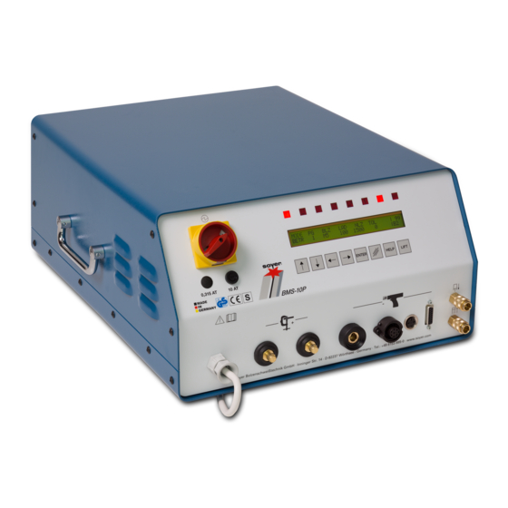
5 Start-up View Front view 1. No function 2. Main switch 3. Fuse element F 1 with fuse 10 AT 4. LCD display 5. LED displays 6. Function keys 7. Air function "forward" 8. Air function "back" 9. Control cable socket 10. -
Page 20: Main Switch
The main switch is used to switch the stud welder on and off. 5.1.2 Description of function keys The BMS-10P stud welder has eight function keys at the front panel which allow different types of functions to be carried out. Description 6.1 "Arrow up"... -
Page 21: Description Of Display
Example: |101 Current charging voltage is 101 V The current capacity of the capacitor bank is displayed at the bottom right. Example BMS-10P: B1 = 33,000 µF | B2 = 99,000 µF Description of operating parameters (MODE) Parameter Description Operation. -
Page 22: Fuse Element
5.1.5 Fuse element The BMS-10P stud welder is protected by a 10 AT fuse. CAUTION Should it become necessary to replace fuses, only use those with specified electrical values. Oversized fuses could either cause defects to the electrical system or a fire. -
Page 23: Description Of Symbols
5.1.7 Description of symbols Symbol Designation Function LED "Ready" LED lights up when stud welder is ready for operation. LED "Stud on LED lights up when earth terminal of stud welder is connected Workpiece" and stud touches the workpiece. LED lights up when pressing release button of welding gun or LED "Release"... -
Page 24: Adjustment Of Operating Modes
Adjustment of operating modes 5.2.1 Starting the stud welder After switching on the stud welder, the 8 LED lamps light briefly. The stud welder carries out a self test. After the self test has been carried out successfully, the stud welder automatically sets the parameters which were last set. -
Page 25: Creating A New Welding Program
Position gun or welding head on workpiece. The LED "Stud on workpiece" lights up. Press the release button of the gun or the welding head or give a triggering signal via the CNC interface. The weld stud is lifted off the workpiece as long as the triggering signal is there. If necessary, check and correct the height of lift according to the specified standard values. -
Page 26: Copying A Welding Program
Copying a welding program Welding programs should be copied when carrying out further parameter tests to save values already determined. Set "MODE" parameter to "OP". Choose a program that is already occupied. Press the "ENTER" key. The following message appears on the display: The stud welder displays the first free program site available where you can store the program to be copied. -
Page 27: Preparation For Start-Up
The start-up procedure described in this section applies to the stud welder in combination with a SOYER stud welding gun. When starting up the stud welder in conjunction with a SOYER stud welding machine (NC, CNC), the work steps must be followed accordingly. -
Page 28: Welding Parameters
(see DVS guideline, Part 1, "Quality assurance of stud welding joints"). The welding parameters were determined with the BMS-10P stud welder and the PS-3 stud welding gun using a lift adjustment of about 2.5 mm. A steel plate with a thickness of 2 mm served as base metal for welding copper-plated CD studs (4.8) as per DIN EN ISO 13918. -
Page 29: Operation
6 Operation NOTE The relevant accident prevention and safety regulations must be complied with when operating the stud welder. NOTE The welding areas must be metallically bright. → If necessary, grind the area to be welded. Switch on mains switch. After switching the stud welder on, all eight LED lamps light up for a short period. -
Page 30: Notes On The "Lifting Test" Operation Mode
Notes on the "Lifting test" operation mode The lifting test allows for the activation of the gun’s lifting magnet thus being able to control the setting. Proceed as follows: Provide ground connection to the workpiece, connect welding gun. Mount stud chuck to the welding gun and insert weld stud into stud chuck. -
Page 31: Adjustment Of Stud Welding Guns
Adjustment of stud welding guns 6.2.1 Basic setting of the stud chuck with set screw The stud chucks with set screw of the PS-1, PS-3, PS- 3K, PS-0K and PS-1K stud welding guns are all of the same style. ... -
Page 32: Start-Up Of Ps-3 Stud Welding Gun
Start-up of PS-3 stud welding gun Note: The PS-3 stud welding gun is only suitable for stud sizes M3 - M8! Ensure depth of immersion / stud protrusion is set between 1.5 mm and 3 mm. After adjustment, check and correct if necessary. Hand-tighten by means of the fixing nut. - Page 33 Switch the BMS-10P stud welder on using the main switch. Choose operation mode "LIFT" on the stud welder. Position welding gun on the workpiece Press push button. The gun lifts the chuck with weld stud away from the workpiece Adjustment of the gun lift is achieved by turning the rear adjustment cap of the welding gun to the left or to the right.
-
Page 34: Start-Up Of Ps-3A Welding Gun
Start-up of PS-3A welding gun The PS-3A welding gun is suitable for PT welding studs as per DIN EN ISO 13918 from M3 – M8 and a maximum stud length of 35 mm. The stud welding gun is usually supplied in a ready-to-use condition. Prior to start-up make sure, however, that the appropriate conversion kit for the weld stud to be used has been installed. - Page 35 Please note: To facilitate the installation of the stud chuck, move or dismantle the support. For doing so, loosen the four Allen screws. Loosen sleeve nut by means of SW 17 socket wrench. Insert the chuck into the spring piston and push it firmly until it comes to a stop (ensure correct mounting position).
- Page 36 The height of lift is the distance for which the weld stud is lifted from the workpiece during the welding process. The height of lift should amount to approx. 2 mm. Switch the BMS-10P stud welder on using the main switch. Choose operation mode "LIFT" on the stud welder. NOTE: If the lift test is carried out on a workpiece which is connected to the earth connection of the stud welder, the drop time will be shown in milliseconds on the display.
- Page 37 Choose operation mode "OP" on the stud welder. Is the charging voltage set according to the stud diameter? Check and correct if necessary. Position welding gun vertically on the workpiece (at a 90- degree angle to the workpiece). Check once again the selected parameters.
-
Page 38: Quality Control
Quality control The quality control serves to monitor the reproducibility of the welding process and to report inadmissible deviations. Thus changes can be detected which impair the quality of the welding results. All welds are monitored when the quality control is switched on. The current weld in real-time is always compared with the stored reference values. - Page 39 "Error" LED blinks. The stud welder is then locked until acknowledging the error message with the "LIFT" key Error messages BMS-10P Text Description...
-
Page 40: Subsequent Collection Or Completion Of Reference Values
6.5.2 Subsequent collection or completion of reference values Depending on the quality and condition of workpieces (rust, forging scales, oil residues), the measuring results of the individual welds are subject to a considerable variance. It might occur e.g. that even perfect welds are reported as defective. This is due to the fact that not enough reference welds have been carried out. -
Page 41: Special Functions
Special functions The following additional special functions can be selected with the BMS-10P stud welder: NOTE Only select the special functions when you are already familiar with the basic functions of the stud welder. The stud welder must be switched off to call up special functions. To call up the respective special functions, certain key combinations must be pressed and kept pressed while switching the stud welder on. -
Page 42: Special Functions - "Extended Submenu
6.6.2 Special functions - "Extended submenu" Various parameters can be adapted via this submenu, which is especially helpful when e.g. using an external control system. To access the submenu, the following procedures are necessary: Simultaneously press function keys "Arrow up" and "Arrow down" and keep them pressed. ... -
Page 43: Special Function "Setting The Language. Display Of Software Version Number
6.6.3 Special function "Setting the language. Display of software version number" This special function serves to select different languages for the display texts and to display the software version number. The languages available are shown in the display. To select this special function, the following procedures are necessary: ... -
Page 44: Special Function "Setting The Feeder Operation
Explanation of parameters Default Parameter Description Range value Piston This parameter sets the after-running time of the stud 0 – 2000 ms feed blow air for the pushing piston in the welding gun/welding head to press the stud out of the stud chuck. - Page 45 This function serves to output a protocol via the RS 232 interface at the stud welder's rear onto a printer. Only printers equipped with a serial interface can be used. Protocol example: Translation: BMS-10P SOYER STUD WELDER – TEST RECORD Item no. : Date : Lot no. : Prod. date : Lot size : Sampl.
- Page 46 Function "Clear protocol" With this function all digits of the protocol function are set to zero i.e. logging deletes all studs and errors collected so far. This function should only be selected after printing out the protocol.
-
Page 47: Quality Control (Stud Welding)
7 Quality control (stud welding) General instructions Provided the SOYER stud welding system is correctly used and the materials are appropriately selected, the strength of the welding joint (welding zone) will always be stronger than that of the stud or base material. -
Page 48: Maintenance
Always disconnect the connecting plug from the mains supply socket before opening the housing of the stud welding system. Only trained and appropriately qualified personnel are allowed to carry out works at the electric mains supply and welding system. NOTE ® Only use original SOYER spare parts. -
Page 49: Cleaning
However, please observe the manufacturer’s specifications on the detergent you intend to use. Replacement of components Components may only be replaced by trained SOYER personnel. The perfect function of your stud welder can only be guaranteed when original SOYER spare parts are used. -
Page 50: Troubleshooting
The following list of errors, their causes and remedies is designed to help you eliminate any trouble immediately on the spot. If you cannot eliminate the trouble, please contact the SOYER customer service responsible for your area or Heinz Soyer Bolzenschweißtechnik GmbH. - Page 51 Stud is too loose or not fully inserted into stud chuck until stop. Insert stud into stud chuck until stop. Replace stud chuck if necessary. Inferior-quality weld studs used e.g. with inaccurate dimensions. Only use SOYER weld studs. Welding energy not correctly adjusted. Adjust welding energy.
-
Page 52: Transport And Storage
The stud welder is robustly designed and has a two-piece metal housing with front and rear panel. Owing to electronic components it should be ensured, however, that transport is free from vibrations. The BMS-10P stud welder has two carrying handles on its top for easy transport and mobile use over short distances. -
Page 53: List Of Standards And Guideline
12 List of standards and guideline • 2014/35/EU Directive on Low Voltage • 2014/30/EU Directive on Electromagnetic Compatibility • EN 60974–1 Arc welding equipment - welding current sources • EN 60974–10 Arc welding equipment - EMC requirements • DVS Information Sheet 0901 Arc stud welding of metallic materials •... - Page 54 Heinz Soyer Bolzenschweißtechnik GmbH www.soyer.de Inninger Straße 14 | 82237 Wörthsee | Tel.: +49 8153 8850 | Fax: +49 8153 8030 | E-mail: info@soyer.de |...
Need help?
Do you have a question about the BMS-10P and is the answer not in the manual?
Questions and answers