Soyer BMS-9 Operating Instructions Manual
Automatic system
Hide thumbs
Also See for BMS-9:
- Operating instructions manual (39 pages) ,
- Operating instructions manual (52 pages) ,
- Operating instructions manual (53 pages)

Related Manuals for Soyer BMS-9


Summary of Contents for Soyer BMS-9
- Page 1 Operating Instructions Automatic system Stud welding devices BMS-9 Automatic BMS-9V Automatic Stud welding gun PS-3A Universal feeder UVR-300...
- Page 2 Stud welding gun PS-3A Universal feeder UVR-300 Operating Instructions Document no.: P00164, 05-2020, Original instructions (English: P00264) All information in this document is the property of Heinz Soyer Bolzenschweißtechnik GmbH. Revision status Document created/amended Editor Date Translation of the origi- Created...
-
Page 3: Table Of Contents
6. Description of the automatic system ....... . 17 7. Description of stud welding devices BMS-9(V) Automatic ....18 7.1. - Page 4 12. Converting/adjusting the automatic system ......77 12.1. Converting the automatic system for the stud diameter 12.1.1 Conversion sets 12.2. Adjusting the device parameters 12.2.1 Explanation of the parameters Operating instructions Soyer Bolzenschweißtechnik...
- Page 5 17. Replacement and conversion parts ....... 100 17.1. Feeder conversion set 17.2. Conversion and replacement parts for the gun and stud chuck Operating instructions Soyer Bolzenschweißtechnik...
-
Page 6: General Information
The devices are designed and constructed in accordance with the general ac- cepted codes of practice. Please note that significant changes to the devices will cause the decla- ration of conformity to become void. Furthermore, the manufacturer's warranty may be rendered invalid. Operating instructions Soyer Bolzenschweißtechnik... - Page 7 D-82237 Wörthsee, Germany Phone: +49(0)8153-8850 Description of the machine: • Function: Stud welding system (unit consisting of feeder and stud welding device) • Type/Model: BMS-9 Automatic / BMS-9V Automatic • Serial number: ________________ • Year of manufacture: ________________ The product is conform with other directives/regulations applicable to the product: •...
-
Page 8: Manufacturer
Web: www.soyer.de, www.soyer.com 1.4 Instruction, training Soyer offers optional and individual instruction in the operation of the devices. Moreover, Soyer offers training for customer-specific use of the devices. Information on the scope and costs of instruction and training can be obtained from Soyer GmbH. -
Page 9: Important Safety Instructions
Do not touch or open, danger to unauthorised per- sons. Danger to persons with medical implants such as pacemakers. The information sign is not a warning sign. It indi- cates important and useful information on the sub- ject. Operating instructions Soyer Bolzenschweißtechnik... -
Page 10: General Safety Instructions
• Starting the device with faulty protection devices is not permitted. Faulty protection devices must be repaired or replaced immediately. Unintentional operation by third parties must be prevented. Operating instructions Soyer Bolzenschweißtechnik... - Page 11 • Work on electric or electronic components may only be performed by trained electrotechnical personnel of Soyer Bolzenschweißtechnik. • Before performing any work on the device, the mains switch of the device must be turned off and the mains plug must be disconnected.
- Page 12 WARNING Danger of fire from hot welding spatters Welding spatters or hot workpieces occurring during the welding process may cause danger of fire. • Do not store combustible or highly flammable materials in the welding area. Operating instructions Soyer Bolzenschweißtechnik...
-
Page 13: Personal Protective Equipment
Welding spatters occur during the welding process. Wear appropriate, non-flammable, heat-resistant safety footwear. Hearing protection Relatively loud welding noises may occur, depending on the welding device and the welding application. In that case, wear appropriate hearing protection. Operating instructions Soyer Bolzenschweißtechnik... -
Page 14: Intended Use Of The Automatic System
These operating instructions and the declaration of conformity only apply if the named devices are used together as described in these operating instructions. With the SOYER® BMS-9 Automatic capacitor discharge stud welding device, pins and threaded studs from M3 to M8 as well as many different weld fasteners made of steel, stainless steel, aluminium and brass can be welded in accordance with DIN EN ISO 13918 (capacitor discharge). -
Page 15: Prerequisites For Personnel
This work must be performed in accordance with the applicable technical rules for electrotechnical devices. All devices of Soyer Bolzenschweißtechnik GmbH must only be opened by Soyer personnel or personnel authorised by Soyer. Operating instructions Soyer Bolzenschweißtechnik... -
Page 16: Transport
Local environmental directives must be observed when disposing of the device. Water-endangering as well as environmentally hazardous substances are to be disposed of in accordance with legal regulations. If applicable, materials must be separated according to regulations. Operating instructions Soyer Bolzenschweißtechnik... -
Page 17: Description Of The Automatic System
ESCRIPTION OF THE AUTOMATIC SYSTEM 6. Description of the automatic system The automatic system consists of the individual devices: Stud welding devices BMS-9 Auto- matic or BMS-9(V) Automatic (See chapter “7. Description of stud welding devices BMS-9(V) Automatic” on page 18) PS-3A stud welding gun (See chapter “8. -
Page 18: Description Of Stud Welding Devices Bms-9(V) Automatic
7.1 Type differentiation The difference between the device types BMS-9 Automatic and BMS-9V Auto- matic described in these instructions lies in the different performances of the ca- pacitor banks and therefore in the welding performance. -
Page 19: Product Features
Monitoring of all functions via a clear function display field 7.2.2 Capacitor discharge stud welding The SOYER® BMS-9 Automatic stud welding device operates according to the principle of capacitor discharge with tip ignition. This system uses the sudden discharge of a capacitor bank to generate arc en- ergy. -
Page 20: Overview Of The Controls
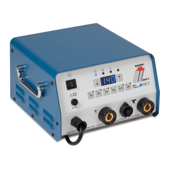
TÜV Rheinland geprüfte Sicherheit M 10A Heinz Soyer Bolzenschweißtechnik GmbH · Inninger Str. 14 · D-82237 Wörthsee · Germany · Tel.: +49 8153 885-0 · www.soyer.com Figure 1: Overview of the front panel of BMS-9 Automatic Item Designation Mains switch for turning the device on/off Selection keys to quickly and directly preselect the stud diameters and the charging voltage (see chapter “12.3.1 Tables for adjusting the... - Page 21 Device back panel Feeder Max. 7 bar Figure 2: Overview of the back panel of BMS-9 Item Designation Connection of feeder hose package: Blow air Connection option of a CNC control interface. Connection of feeder hose package: Control cable to the feeder...
-
Page 22: Displaying The Operating States
The LED lights up when the trigger button on the welding gun is pressed. Malfunction The LED lights up when a malfunction of the stud welding device occurs. Then, observe chapter “13.5 Malfunctions with an error mes- sage on the stud welding device” on page 96. Operating instructions Soyer Bolzenschweißtechnik... -
Page 23: Technical Data On Bms-9(V) Automatic Stud Welding Device
Standard gun PS-3A for automatic operation Welding area BMS-9 Automatic: M3 - M8 or Ø 3 - 8 mm for steel, stainless steel, aluminium and brass (M8 or Ø 8 for alu- minium and brass limited, depending on the respective requirements) BMS-9V Automatic: M4 - M10 or Ø... -
Page 24: Permitted Stud Welding Guns
Hazards for the operator may occur when a wrong welding gun is used. • Only use welding guns hereinafter permitted by Soyer. The use of other guns or guns from another manufacturer will invalidate the declarations of conformity and warranties of Soyer. -
Page 25: Cleaning The Stud Welding Device
Work on electrical devices and components may only be performed by skilled electricians in accordance with electrotechnical regulations. • Make sure that no liquids get into the device. Do not use aggressive detergents for cleaning the device. Operating instructions Soyer Bolzenschweißtechnik... - Page 26 Incorrect cleaning may cause damage to the device. • Make sure that no liquids get into the device. • Do not use aggressive detergents for cleaning the device. The frequency of cleaning depends on the operating conditions of the stud weld- ing device. Operating instructions Soyer Bolzenschweißtechnik...
-
Page 27: Description Of The Ps-3A Stud Welding Gun
The height of the lift is also decisive for the welding result. The height of lift can be determined via the lift time using the BMS-9(V) stud weld- ing device. See chapter chapter “12.3.3 Adjusting the lift time (height of lift) in the setting mode”... -
Page 28: Inserting The Stud Feed Hose
With the stud feed hose, ensure that the hose end (a) is straight, clean and free of burrs. Place the stud feed pipe union nut (b) onto the hose. Step 2: Insert the hose into the stud feed pipe (a) until the stop. Operating instructions Soyer Bolzenschweißtechnik... - Page 29 For this reason: To avoid damage to the clamp of the stud feed pipe in the gun, it is recommended to always remove the stud feed pipe from the gun when chang- ing the hose. Operating instructions Soyer Bolzenschweißtechnik...
-
Page 30: Technical Data For The Ps-3A Stud Welding Gun
Stud length Adjustable stud chuck up to a maximum of 35 mm Longer stud lengths with optional accessory possible Stud welding devices The gun is approved for operation on the following SOYER® stud welding devices: • BMS-9 Automatic • BMS-9V Automatic •... -
Page 31: Cleaning The Stud Welding Gun
Welding spatters and slag can have sharp edges. • Wear protective gloves when cleaning. We recommend the use of SOYER® separating spray to prevent impuri- ties from welding spatters and slag and to simplify the cleaning process (order number: M01464). -
Page 32: Description Of The Stud Chuck For Ps-3A
Stud Plunger Stud chuck Distance sleeve The stud chuck must be adjusted to suit the length and diameter of the welding stud. The stud chuck can hold studs with a length of up to 35 mm. Operating instructions Soyer Bolzenschweißtechnik... -
Page 33: Adjusting The Stud Chuck
3 mm above the stud chuck with its flange upper edge. 1.5 - 3 mm Step 4: Place a distance sleeve or filling dis- tance part combination between the plunger and the stud chuck. The adjustment is complete. Operating instructions Soyer Bolzenschweißtechnik... -
Page 34: Inserting The Stud Chuck And Stud Feed Pipe
In the following steps, the stud chuck containing a stud is inserted. Step 3: Replacing the stud chuck is made easier by disassembling or moving the support. To do this, loosen the four Allen screws (a). Remove the union nut (b). Operating instructions Soyer Bolzenschweißtechnik... - Page 35 33) above the stud chuck. If not, the stud must either be moved into this position manually or the gun must be hit with compressed air for the plunger to push the stud and position it. Operating instructions Soyer Bolzenschweißtechnik...
- Page 36 1.5 - 3 mm above the support. Fix the support into place after adjusting with the four Allen screws. 1.5 - 3 mm The assembly is complete. Operating instructions Soyer Bolzenschweißtechnik...
-
Page 37: Description Of The Uvr-300 Universal Feeder
The feeder intensity can be adjusted via a potentiometer. This is controlled via a control panel with membrane keypad. LED displays, signal transmitters on the stud escapement and the feeder interface in the stud welder enable a regulated function in both continuous or automatic mode. Operating instructions Soyer Bolzenschweißtechnik... -
Page 38: Safety Information For Uvr-300
Each time, before you start the system, check that the stud feed hose is correctly inserted on both sides, into the feeder and the gun. • Only use stud feed hoses from Soyer GmbH. • Never bridge the safety pressure switch at the cover hood (do not trigger the switch if the protective hood has been removed). -
Page 39: Overview Of Uvr-300
LED operating displays (see “10.3” on page 42) Feed opening for the stud feed hose Safety switch to disconnect the compressed air when the protective hood is not attached. WARNING WARNING The safety switch must not be bridged! Operating instructions Soyer Bolzenschweißtechnik... - Page 40 Figure 7: Overview of the universal feeder connections Item Designation Blow air regulator Supply air line Observe the maximum permitted pressure. Hose package with all tubes and hoses to connect to the stud welding device and with the mains plug for the feeder. Operating instructions Soyer Bolzenschweißtechnik...
- Page 41 Figure 8: Overview of the transport area Item Designation Feeder bowl with welding studs Connection piece for the stud feed hose (replaceable part) Outlet rail (replaceable part) Blow-off nozzle to separate studs from on top of one another. Hold-down plate Stud retainer Operating instructions Soyer Bolzenschweißtechnik...
-
Page 42: Led Operating Displays (Device Front Panel)
The LED lights up when the vibration drive is in operation. Automatic The LED lights up when automatic mode is switched on. No function There are no LEDs for the UVR-300. Malfunction The LED lights up when there is a malfunction. Operating instructions Soyer Bolzenschweißtechnik... -
Page 43: Function Keys And Special Functions
Function key: ON/OFF, to switch the controls on/off. Function key: Operating mode to switch to • Manual mode (continuous operation) • Automatic mode. Function key: Reload to convey a stud to the welding gun. You can also reload by triggering the welding gun. Operating instructions Soyer Bolzenschweißtechnik... -
Page 44: Special Functions (Potentiometer)
The reload time can be regulated based on the stud diameter. Turning to the left increases the time; turning to the right shortens the time. P 2: Frequency adjustment for the feeder vibration drive. Operating instructions Soyer Bolzenschweißtechnik... -
Page 45: Converting The Universal Feeder
Connection pieces for the stud feed hose Threaded studs M10, aid to remove the stud retainer Outlet rails with distance piece All conversion set parts can be ordered separately. For this, please observe chap- ter “17.1 Feeder conversion set” on page 100. Operating instructions Soyer Bolzenschweißtechnik... -
Page 46: Carrying Out The Conversion
Disconnect the main air feed at the back panel of the device. • Remove the cover hood (b) via the fastening screws (c) on both sides. Reassemble the cover hood after the work, as the feeder cannot start without this. Operating instructions Soyer Bolzenschweißtechnik... - Page 47 (a). Studs which are parallel to one another or on top of one another (b) then fall off the plate. After the adjustment, tighten the clamp screws (b) again. The step width is adjusted. Operating instructions Soyer Bolzenschweißtechnik...
- Page 48 Remove the hose connection (a) from the feeder. The hose connection is fastened with a spring-loaded pin. Through the bore hole of the top panel (b), you can loosen or re-attach the threaded pin with an Allen key if required. Operating instructions Soyer Bolzenschweißtechnik...
- Page 49 Remove the required hose connection from the conversion set. Each hose connection is labelled with the stud diameter it must be used for (a). Step 3: Ensure that the safety interlock (a) is unobstructed and can be moved easily. Operating instructions Soyer Bolzenschweißtechnik...
- Page 50 Insert the hose into the connection piece until the stop. The hose connection has been replaced. To replace the stud feed hose on the gun, please observe chapter “8.1 Insert- ing the stud feed hose” on page 28 Operating instructions Soyer Bolzenschweißtechnik...
- Page 51 (b). To remove and insert the stud retainer, use a screw or a stud with diameter M 10 which you screw into the centre (c). CAUTION CAUTION Remove the screw/stud again after inserting the barrel. Operating instructions Soyer Bolzenschweißtechnik...
- Page 52 Step 4: Open the tommy screw (a) and remove the panel (b) with the compressed air connection (c). CAUTION CAUTION Ensure that the compressed air line and the compressed air nozzle are not damaged by this. Operating instructions Soyer Bolzenschweißtechnik...
- Page 53 Insert the outlet rail (a) and the panel with the compressed air connection (b). Fasten both with the tommy screw (c) and the fastening screw (d). CAUTION CAUTION Ensure that the compressed air line and the compressed air nozzle are not damaged by this. Operating instructions Soyer Bolzenschweißtechnik...
- Page 54 If not, open the tommy screw (b) and push the block on the tran- sition (c) until there is a clean, aligning transition. Step 8: Attach the hold-down plate with the fastening screw (a) above the outlet rail. The outlet rail has been changed. Operating instructions Soyer Bolzenschweißtechnik...
- Page 55 Remove the limit stop distance plate (a) by opening the tommy screw (b). Step 2: Remove the required limit stop distance plate from the conver- sion set. Each limit stop distance plate is labelled with the stud diameter it must be used for (a). Operating instructions Soyer Bolzenschweißtechnik...
- Page 56 ESCRIPTION OF THE UNIVERSAL FEEDER Replacing the limit stop distance plate Step 3: Attach the limit stop distance plate (a) and clamp it with the tommy screw (b). The limit stop distance plate has been changed. Operating instructions Soyer Bolzenschweißtechnik...
-
Page 57: Adjusting The Feeder
“12. Converting/adjusting the automatic system” on page 77. 10.6.1 Adjusting the blow air regulator Figure 13: Blow air regulator Item Designation Manometer Pressure regulator Pull out to make the adjustment, push back in after adjusting the pres- sure. Operating instructions Soyer Bolzenschweißtechnik... -
Page 58: Adjusting The Blow-Off Nozzles
Designation Blow-off nozzles Part being blown off (example) Valve for regulating the blow-off air The blow-off nozzles prevent an incorrectly positioned stud from being transport- ed further. The blow-off air is adjusted via a central valve. Operating instructions Soyer Bolzenschweißtechnik... -
Page 59: Adjusting The Transport Speed In The Feeder Bowl
Max.: Maximum transport speed The transport speed to be adjusted depends on the type and size of the welding studs. The welding studs must be transported upwards evenly, without gaps and without being pushed on top of one another. Operating instructions Soyer Bolzenschweißtechnik... -
Page 60: Readjusting The Limit Switch
The limit switches must be readjusted when they are not active in the respective position of the slide (not lit up). If the limit switches are not active, no notification about the end position of the slide is issued to the controls, and the system stops. Operating instructions Soyer Bolzenschweißtechnik... -
Page 61: Correcting Feeder Malfunctions
The control cable and/or mains cable are not con- nected properly or they are damaged. Connect the cable properly or inspect it for damage and replace if required. The power supply for the feeder is defective. Have this checked by an electrician. Operating instructions Soyer Bolzenschweißtechnik... - Page 62 Check the conversion parts and install them accord- ing to the stud diameter. Insufficient quality of the welding studs. Only use SOYER® welding studs which are suitable for automated systems. Stud falls through the Insufficient quality of the welding studs.
- Page 63 Regulate the pressure (observe maximum pressure). gun. Problems with the stud feed hose. Check the internal diameter. Check for damage or kinks (and radii which are too small). Check the hose ends, chamfer the inside of the hose end if necessary. Operating instructions Soyer Bolzenschweißtechnik...
-
Page 64: Technical Data For The Uvr-300
UVR-300 universal feeder Item no. P01740 Working area SOYER® threaded studs and pins with flange according to DIN EN ISO 13918 of M3 - M8 or Ø 3 - 8 mm and 6 - 40 mm length Material Steel, stainless steel, aluminium and brass Feeding capacity Approx. -
Page 65: Cleaning The Uvr-300
Do not use aggressive detergents for cleaning the device. Please make sure that any cleaning waste is disposed of in an environmentally safe manner. Please observe the instructions of the detergent manufacturer. The frequency of cleaning depends on the operating conditions of the feeder. Operating instructions Soyer Bolzenschweißtechnik... -
Page 66: Setup And Connection Of The Automatic System
ETUP AND CONNECTION OF THE AUTOMATIC SYSTEM 11. Setup and connection of the automatic system The following describes how the devices • Stud welding device BMS-9(V) Automatic • Welding gun PS-3A • Universal feeder UVR-300 are connected to power and connect together to the automatic system. - Page 67 Hose package with welding and control cable and compressed air hose to connect to the stud welding device. The following describes how to connect the device to power and connect the de- vices together step by step. Operating instructions Soyer Bolzenschweißtechnik...
-
Page 68: Connections On The Stud Welding Device
Sicherheit M 10A Heinz Soyer Bolzenschweißtechnik GmbH · Inninger Str. 14 · D-82237 Wörthsee · Germany · Tel.: +49 8153 885-0 · www.soyer.com Check that the device switch (a) is off and after installation, con- nect the stud welding device to power supply using the mains plug (b = mains cable). - Page 69 Sicherheit M 10A Heinz Soyer Bolzenschweißtechnik GmbH · Inninger Str. 14 · D-82237 Wörthsee · Germany · Tel.: +49 8153 885-0 · www.soyer.com • Plug the welding cable into the socket (a) and turn the plug to the right up to the stop.
- Page 70 Feeder connection – blow air Feeder Max. 7 bar Connect the blow air hose (a) from the feeder hose package. Observe the maximum permitted pressure. Observe the labelling on the connection and hose, do not mix up! Operating instructions Soyer Bolzenschweißtechnik...
- Page 71 Connect both compressed air hoses for the slide (a) from the hose package. Observe the coloured markings (V: blue; Z: black) on the connection and the hose, do not mix up! The back panel of the device is connected. Operating instructions Soyer Bolzenschweißtechnik...
-
Page 72: Connections On The Feeder
Observe the maximum permitted pressure. Step 2: Stud feed hose Insert the stud feed hose into the connection piece (a) until the stop. The stud feed hose and connection piece must match the stud diameter being processed. Operating instructions Soyer Bolzenschweißtechnik... - Page 73 If the stud feed hose is used incorrectly, or an unsuitable hose is used, there is a risk of injury due to ejected welding studs. • Only use original stud feed hoses from Soyer GmbH. • Only ever use stud feed hoses which match the stud diameter.
-
Page 74: Connections On The Welding Gun
With the stud feed hose, ensure that the hose end (a) is straight, clean and free of burrs. Place the stud feed pipe union nut (b) onto the hose. Step 2: Insert the hose into the stud feed pipe (a) until the stop. Operating instructions Soyer Bolzenschweißtechnik... -
Page 75: Information About Connecting The Earth Cable
Then connect the earth cable to the workpiece (ensure a conductive Heinz Soyer Bolzenschweißtechnik GmbH · Inninger Str. 14 · D-82237 Wörthsee · Germany · Tel.: +49 8153 885-0 · www.soyer.com connection). Then attach the earth clamps to the workpiece so that the welding gun is positioned in the centre of the connecting line of the two earth clamps. - Page 76 Ideal condition, stud is located in the centre of the two earth connections. Asymmetrical earth connection The arc is deflected to the side where there is a lower current density. Workpiece geometry Additional workpiece masses disturb the arc symmetry. Operating instructions Soyer Bolzenschweißtechnik...
-
Page 77: Converting/Adjusting The Automatic System
The feeder is supplied with the corresponding conversion parts. You can find the conversion parts required for the gun in chapter “17.2 Conversion and replace- ment parts for the gun and stud chuck” on page 102. Operating instructions Soyer Bolzenschweißtechnik... -
Page 78: Adjusting The Device Parameters
86. Automatic reload: ON with automatic stud feed, OFF with manual stud feed. Trigger delay: Do not change. Leave on the factory setting. The trigger delay is only used for CNC or robot operation. Operating instructions Soyer Bolzenschweißtechnik... -
Page 79: Adjusting The Main Parameters
Ø7,1 Ø5 Step 3: After approx. 3 seconds, the button Ø 3 is activated and the feeder operating Ø3 Ø4 Ø5 Ø6 mode is displayed on the screen. To adjust the parameters, see the following table. Operating instructions Soyer Bolzenschweißtechnik... - Page 80 [Factory setting: 0.5] Ø 7.1 Feeder reload time 0 to 20 s, in 1 s stages (Ø 8)* [Factory setting: 1] Ø 8 End the adjustment menu. (Ø 10)* *) Buttons in brackets for the BMS-9V Automatic Operating instructions Soyer Bolzenschweißtechnik...
-
Page 81: Adjusting The Ancillary Parameters
Ø5 Step 3: After approx. 3 seconds, the button Ø 3 is activated and the number of repair Ø3 Ø4 Ø5 Ø6 attempts is displayed on the screen. To adjust the parameters, see the following table. Operating instructions Soyer Bolzenschweißtechnik... - Page 82 [Factory setting: 1] Ø 7.1 Trigger delay 0.0 to 1.0 s, in 0.1 s stages (Ø 8)* [Factory setting: 0] Ø 8 End the adjustment menu. (Ø 10)* *) Buttons in brackets for the BMS-9V Automatic Operating instructions Soyer Bolzenschweißtechnik...
-
Page 83: Adjusting The Charging Voltage And Lift Time On The Stud Welding Device
Lift time In the tables, you will also find experience values for adjusting the lift time (see chapter “12.3.3 Adjusting the lift time (height of lift) in the setting mode” on page 86). Operating instructions Soyer Bolzenschweißtechnik... - Page 84 ONVERTING ADJUSTING THE AUTOMATIC SYSTEM Adjustment table Adjustment guide BMS-9 Automatic BMS-9 Automatic Device button Ø Ø3 Ø4 Ø5 Ø6 Ø7.1 Ø8 [mm] Corresponds to ------- threaded stud Charging voltage preset [V] Guideline value for With gun PS-9: 6 - 7 ms...
-
Page 85: Adjusting The Charging Voltage
TÜV Rheinland geprüfte Sicherheit M 10A Heinz Soyer Bolzenschweißtechnik GmbH · Inninger Str. 14 · D-82237 Wörthsee · Germany · Tel.: +49 8153 885-0 · www.soyer.com Step 3: On the display, a charging voltage value will be displayed in [V]. -
Page 86: Adjusting The Lift Time (Height Of Lift) In The Setting Mode
Connect the device as described in chapter “11.6 Information about connecting the earth cable” on page 75. Step 2: Check that the stud welding device is switched off. Step 3: Equip the gun with a welding stud. Operating instructions Soyer Bolzenschweißtechnik... - Page 87 If the desired lift time is set, switch off the stud welding device and switch it back on again. Afterwards, the device will be back in operating mode. Operating instructions Soyer Bolzenschweißtechnik...
- Page 88 • If the lifting cycle takes place without the notification that the studs are on the workpiece, instead of the lift time, [- - -] is displayed, as no earth connection was present. Operating instructions Soyer Bolzenschweißtechnik...
-
Page 89: Welding With The Automatic System
Check or convert the automatic system according to chapter “12. Converting/adjusting the automatic system” on page 77. Step 4: Fill the feeder bowl (a) with welding studs. Only use SOYER® welding studs. Observe the permitted fill weight. Operating instructions Soyer Bolzenschweißtechnik... - Page 90 Hold guns with stud ejectors fac- ing downwards and do not point them at persons or animals. Step 8: Ensure that the welding points on the stud and workpiece are metallically bright. Operating instructions Soyer Bolzenschweißtechnik...
-
Page 91: Refilling The Feeder During Operation
Observe the per- mitted filling weight and that the stud type is the same. Afterwards, assemble the protective hood. The compressed-air supply is re-es- tablished and the work can be continued. Operating instructions Soyer Bolzenschweißtechnik... -
Page 92: Notes On Checking The Quality Of The Weld
ELDING WITH THE AUTOMATIC SYSTEM 13.2 Notes on checking the quality of the weld If the SOYER® stud welding equipment is handled correctly and the correct ma- terials are selected, the strength of the welding joint (welding zone) is always greater than the strength of the stud or the base material. - Page 93 Note Poor welding joint, e.g. due to a blow effect or a welding gun that was shaken or applied at a slant. The stud flange is not welded completely and has visible imperfections. Undercuts are visible. Operating instructions Soyer Bolzenschweißtechnik...
-
Page 94: Switching Off The Devices
Switch off the feeder at the mains switch. Switch off the main compressed air or disconnect the feeder from the com- pressed-air supply. Ensure that the devices cannot be switched on and used by unauthorised per- sons. Operating instructions Soyer Bolzenschweißtechnik... -
Page 95: Welding Defects And Their Causes
ELDING WITH THE AUTOMATIC SYSTEM 13.4 Welding defects and their causes In the following, the most common welding errors, possible causes and trouble- shooting are described. Please contact Heinz Soyer Bolzenschweißtechnik GmbH if a problem cannot be solved. Error Possible cause and troubleshooting Device does not weld, no Stud welding device is not switched on. -
Page 96: Malfunctions With An Error Message On The Stud Welding Device
DANGER Dangers during troubleshooting During troubleshooting, various dangers may occur. • Soyer Bolzenschweißtechnik GmbH devices must only be opened by Soyer personnel or personnel authorised by Soyer. • For troubleshooting, the device must be disconnected from the main power supply and secured against accidental switch-on. - Page 97 In the event of error code E05, excess temperature, the welding device cannot be used until the displayed error message disappears. • If the devices works with a reduced charging current due to a high internal tem- perature, the LED “Malfunction” flashes. Operating instructions Soyer Bolzenschweißtechnik...
-
Page 98: Maintenance And Repair
AINTENANCE AND REPAIR 14. Maintenance and repair Maintenance and repair of the stud welding device and the stud welding guns should only be performed by Heinz Soyer Bolzenschweißtechnik GmbH or au- thorised specialists. 15. Service If servicing is required, please contact: Heinz Soyer Bolzenschweißtechnik GmbH... -
Page 99: Warranty Conditions
When using welding studs from external manufacturers, we do not assume any warranty for proper function of the automatic system and the quality of the welding joint. Operating instructions Soyer Bolzenschweißtechnik... -
Page 100: Replacement And Conversion Parts
Figure 17: Conversion set exchange parts (1) Individual parts in the feeder conversion set (1) Item Designation Dimensions Item no. Adjustment plate (limit stop dis- F05343 tance plate) F05344 F05345 F05346 Ø 7.1 mm F05347 F05348 Operating instructions Soyer Bolzenschweißtechnik... - Page 101 Limit stop for fixing bracket F05335 Lens head screw M5 x 12 mm M03870 Guide rail F05572 Hexagonal Allen screw M4 x 8 mm M01563 Distance piece F05349 F05350 F05351 F05352 Ø 7.1 mm F06115 F05290 Operating instructions Soyer Bolzenschweißtechnik...
-
Page 102: Conversion And Replacement Parts For The Gun And Stud Chuck
M4 / M5 F02032 M6-M8 F02570 Ø 7.1 mm Stud feed hose F01081 (Always cut by F01082 metre. Please state desired length in F01083 metres). Item quantity 1 F01084 means 1 m. M8 / Ø 7.1 mm F01085 Operating instructions Soyer Bolzenschweißtechnik... - Page 103 M4 x 8 mm F06400 studs M5 x 8 mm F06401 M6 x 8 mm F06402* M8 x 10 mm F06403* Pushing piston for F04865 short studs F04866 M8 / Ø 7.1 mm F04867 * Availability on request Operating instructions Soyer Bolzenschweißtechnik...
- Page 104 Heinz Soyer Bolzenschweißtechnik GmbH Inninger Straße 14 82237 Wörthsee Tel.: 0049-8153-885-0 Mail: info@soyer.de...
Need help?
Do you have a question about the BMS-9 and is the answer not in the manual?
Questions and answers