Table of Contents
Advertisement
Quick Links
Advertisement
Table of Contents
Troubleshooting

Related Manuals for ILX Lightwave LDT-5900 Series


Summary of Contents for ILX Lightwave LDT-5900 Series
-
Page 3: Table Of Contents
T A B L E O F C O N T E N T S ABLE OF ONTENTS Table of Contents ......... . . i List of Figures . - Page 4 T A B L E O F C O N T E N T S Available Options and Accessories ........4 Specifications .
- Page 5 T A B L E O F C O N T E N T S Chapter 3 Remote Operations Remote Configuration ..........41 GPIB Configuration .
- Page 6 T A B L E O F C O N T E N T S Chapter 5 Calibration and Troubleshooting Calibration ........... . 118 Recommended Equipment .
-
Page 7: List Of Figures
L I S T O F F I G U R E S IST OF IGURES Figure 2.1 Front Panel ........9 Figure 2.2 Rear Panel . - Page 8 L I S T O F F I G U R E S LDT-5980/ 5948...
-
Page 9: List Of Tables
L I S T O F T A B L E S IST OF ABLES Table 2.1 PID Constant Values ......22 Table 3.1 Substitute Parameter Names . - Page 10 L I S T O F T A B L E S Table 4.1 GPIB Command Summary Reference List ... . 62 Table 5.1 Problem and Action ......128 Table 5.2 LDT-5980/5948 Error Codes .
-
Page 11: Safety And Warranty Information
• Prolonged storage under adverse conditions • Failure to perform intended measurements or functions If necessary, return the instrument to ILX Lightwave, or authorized local ILX Lightwave distributor, for service or repair to ensure that safety features are maintained (see the contact information on page All instruments returned to ILX Lightwave are required to have a Return Authorization Number assigned by an official representative of ILX Lightwave Corporation. -
Page 12: Safety Symbols
Technical specifications including electrical ratings and weight are included within the manual. See the Table of Contents to locate the specifications and other product information. The following classifications are standard across all ILX Lightwave products: • Indoor use only • Ordinary Protection: This product is NOT protected against the harmful ingress of moisture. -
Page 13: Warranty
Returning an Instrument If an instrument is to be shipped to ILX Lightwave for repair or service, be sure to: Obtain a Return Authorization number (RA) from ILX Customer Service. Attach a tag to the instrument identifying the owner and indicating the required service or repair. -
Page 14: Comments, Suggestions, And Problems
W A R R A N T Y Comments, Suggestions, and Problems To ensure that you get the most out of your ILX Lightwave product, we ask that you direct any product operation or service related questions or comments to ILX Lightwave Customer Support. - Page 15 ILX Lightwave instrument: Description of the problem: If ILX Lightwave determines that a return to the factory is necessary, you are issued a Return Authorization (RA) number. Please mark this number on the outside of the shipping box.
- Page 16 W A R R A N T Y LDT-5980/ 5948...
-
Page 17: Introduction And Specifications
Prolonged storage under adverse conditions Failure to perform intended measurements or functions If necessary, return the LDT-5900 Series Temperature Controller to ILX Lightwave for service and repair to ensure that safety features are maintained. Follow the “Returning an Instrument” process described on page xi. -
Page 18: Product Overview
C H A P T E R Prod uct Overview Product Overview The LDT-5900 Series Temperature Controllers consists of two family members, the LDT-5948 60W Precision Temperature Controller and the LDT-5980 120W High Power Temperature Controller. These instruments are bi-directional current sources with precision measurement circuits to monitor and control the temperature of the device under test. -
Page 19: Installing The Ldt-5900
100-240 VAC (all values RMS), from 50-60 Hz. Tilt-Foot Adjustment The LDT-5900 Series comes standard with folding front legs and two rear feet for use as a benchtop instrument. Extend the front legs to tilt the front panel upward, making it easier to read the display. -
Page 20: Available Options And Accessories
Series Temperature Controllers. Unless properly configured, use of other cables may lead to fire hazard and may limit the controller’s maximum output current. See Chapter 2 for more details. Other laser diode mounts, sensors and accessories are available. Please contact ILX Lightwave for information on additional options for your applications. LDT-5980/ 5948... -
Page 21: Specifications
I N T R O D U C T I O N A N D S P E C I F I C A T I O N S C H A P T E R Sp ecifica t ions Specifications TEMPERATURE CONTROL LDT-5948... - Page 22 I N T R O D U C T I O N A N D S P E C I F I C A T I O N S C H A P T E R Sp ecifica t ions Thermistor Sensing Current 10 A / 100 A / 1 mA Useable Thermistor / RTD Range...
-
Page 23: Figure 2.3 Trigger Out
I N T R O D U C T I O N A N D S P E C I F I C A T I O N S C H A P T E R Sp ecifica t ions GENERAL LDT-5948 LDT-5980... - Page 24 I N T R O D U C T I O N A N D S P E C I F I C A T I O N S C H A P T E R Sp ecifica t ions LDT-5980/ 5948...
-
Page 25: Front Panel Overview
C H A P T E R PERATIONS This chapter describes the operation of the LDT-5900 Series Temperature Controller. It is divided into five sections covering front panel overview, rear panel overview, general operations, front panel operations and basic TEC operations. -
Page 26: Rear Panel Overview
O P E R A T I O N S C H A P T E R Rea r Pa nel Overview Rear Panel Overview Rear Panel Controls and Connections Figure 2.2 Rear Panel AC Power Entry Module The AC Power Entry Module is located on the lower right side of the rear panel. The LDT-5900 must be connected to a properly rated AC source in order to operate. -
Page 27: Gpib Connector
O P E R A T I O N S C H A P T E R Rea r Pa nel Overview GPIB Connector The GPIB interface connector is located in the upper left corner of the rear panel. Refer to Figure 2.2. The 24-pin GPIB interface connector is tapered to ensure proper orientation. -
Page 28: General Operation
Remote operations are discussed in Chapter 3 and the command reference is discussed in Chapter 4. Warm Up and Environmental Considerations Operate the LDT-5900 Series Temperature Controller at an ambient temperature range of 10 C to 40 C. -
Page 29: Tec Grounding Considerations
The CC-59X Series cables are specifically designed to be compatible with the 5900 Series Temperature Controllers. See the ILX Lightwave product catalogue or contact ILX Customer Service (see page xii for contact information) for information about the cable. -
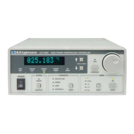
Page 30: Front Panel Operation
Front Pa nel Opera t ion Front Panel Operation Figure 2.5 shows the front panel of the LDT-5900 Series Temperature Controller. The key operating parameters for the LDT-5900 Series Temperature Controller can be set, adjusted, and displayed through various menus accessible by using the front panel push buttons (keys) and knobs. -
Page 31: Adjust Section
O P E R A T I O N S C H A P T E R Front Pa nel Opera t ion The error indicators (LEDs) in the display section are described as follows: • TEMP LIMIT - The Temperature Limit LED will be RED when either the Low Temperature or the High Temperature Limit is met or exceeded and the output will be shut off. -
Page 32: Measurement And Setpoint
C H A P T E R Front Pa nel Opera t ion Measurement and Setpoint By default, the LDT-5900 Series Temperature Controller displays the temperature measurement from the selected sensor in C. Using the DISPLAY / MENU arrow F, K) -
Page 33: System Section
O P E R A T I O N S C H A P T E R Front Pa nel Opera t ion System Section The System section of the front panel contains the MAIN / LOCAL button and the REMOTE indicator. - Page 34 The DISPLAY / MENU up and down arrow keys scroll thru the error log, which lists the most recent error at the top. Table 3.7 in Chapter 3 lists the error codes for the LDT-5900 Series Temperature Controllers. ERROR LOG 00000000003/7...
- Page 35 O P E R A T I O N S C H A P T E R Front Pa nel Opera t ion Buttons The fourth page of the system menu allows the user to set the beep for the buttons either on or off by using the adjust knob and then pressing the ENTER / LOCK key.
- Page 36 O P E R A T I O N S C H A P T E R Front Pa nel Opera t ion When the setpoint reaches the specified Stop temperature, the next pulse will reset the setpoint back to the Start temperature. The setpoint cannot exceed the Stop temperature, and any attempt to step beyond the Stop temperature will instead reset the setpoint back to the Start temperature.
-
Page 37: Parameter Section
O P E R A T I O N S C H A P T E R Front Pa nel Opera t ion A/D Setup The last page of the system menu allows the user to set up the A/D filter to reject either 50 Hz or 60 Hz AC line noise. -
Page 38: Pid / Auto-Tune
0 - 999.999 Derivative 0 - 999.999 The LDT-5900 Series Temperature Controllers have an auto-tune algorithm that will help the user determine nominal values for the PID coefficients. While the auto-tuned values typically provide acceptable stability and overshoot for a given thermal system, these values can usually be optimized through further user tuning, as described later in this section. -
Page 39: Auto-Tune Operation
Front Pa nel Opera t ion Auto-Tune Operation The auto tune algorithm in the LDT-5900 series of temperature controllers will calculate a thermal system's PID coefficients through an iterative PID temperature control process. Figure 2.6 describes the tuning process pictorially. - Page 40 O P E R A T I O N S C H A P T E R Front Pa nel Opera t ion After the temperature has stabilized, the integral term (I term) is then added to the control loop (Point 5 on Graph). The I term is then increased until it causes the temperature to oscillate around the user defined tuning set point (Point 7 on Graph).
-
Page 41: Modifying The Pid Coefficients
O P E R A T I O N S C H A P T E R Front Pa nel Opera t ion If “AutoTune N/A” is displayed, the Auto-Tune feature (and modification of the PID constants) is not available for the currently selected control mode. To abort an Auto-Tune that is in progress, press the OUTPUT key. -
Page 42: Sensor
O P E R A T I O N S C H A P T E R Front Pa nel Opera t ion LDT-59XX TEMPERATURE CONTROLLER P: [0030.00] I: 0000.800 SENSOR The Sensor parameter allows the user to select the type of sensor for the application: Thermistor, IC-V, IC-I or RTD. -
Page 43: Limits
O P E R A T I O N S C H A P T E R Front Pa nel Opera t ion LDT-59XX TEMPERATURE CONTROLLER C1: [001.125] C2: [002.347 The coefficients can be modified by using the Adjust Knob and then pressing the ENTER / LOCK key. -
Page 44: Save / Recall
O P E R A T I O N S C H A P T E R Front Pa nel Opera t ion SAVE / RECALL The Save / Recall menu functions are used to quickly configure the LDT-5900 Series Temperature Controller’s parameters to user-determined pre-set values. LDT-59XX TEMPERATURE CONTROLLER Save 0: [1]... -
Page 45: Mode Section
O P E R A T I O N S C H A P T E R Front Pa nel Opera t ion RECALL The Recall function is used to return the LDT-5900 to a previously defined state or configuration. To recall a saved configuration (or unconfigured bin) of the LDT- 5900, select the Recall parameter from the SAVE / RECALL menu. -
Page 46: Snsr
O P E R A T I O N S C H A P T E R Front Pa nel Opera t ion Selecting T will enable the instrument to operate in constant temperature mode when OUTPUT is turned on. In T mode, the controller output current to the TEC is continuously adjusted to maintain the setpoint temperature at the sensor. -
Page 47: Rac
O P E R A T I O N S C H A P T E R Front Pa nel Opera t ion In V mode, the controller output current is continuously adjusted to maintain the setpoint voltage across the TEC. VTE mode is intended for applying a constant voltage into a typical TE load (.1 <... - Page 48 O P E R A T I O N S C H A P T E R Front Pa nel Opera t ion LDT-59XX TEMPERATURE CONTROLLER 001.5243 To activate this feature, press the OUTPUT key. The instrument will measure and display the resistance of the TE module, and then turn output off.
-
Page 49: Basic Tec Operation Instructions
Ba sic TEC Op era t ion Inst ruct ions Basic TEC Operation Instructions This procedure is for basic setup and operation of the LDT-5900 Series Temperature Controllers. See General Guidelines for Sensor Selection and Safety Limits for detailed information about the specific sensors and control parameters. -
Page 50: General Guidelines For Sensor Selection And Safety Limits
This section presents some guidelines to assist in selecting the optimal settings for your application. Sensor Options The LDT-5900 Series Temperature Controllers can measure temperature through a variety of sensor options; thermistors, IC sensors (IC-I, IC-V) or RTDs. Thermistor - When a thermistor sensor is selected, the LDT-5900 measures temperature based on using a negative temperature coefficient (NTC) thermistor. -
Page 51: Figure 2.7 Example Thermistor Resistance Vs. Temperature
O P E R A T I O N S C H A P T E R Ba sic TEC Op era t ion Inst ruct ions supply current selection depends on the thermistor operating temperature range and the required temperature resolution. A general rule of thumb for a 10 k thermistor is to use the 10 A range for temperatures between -30 C and +30 and the 100 A range for temperatures between 10... - Page 52 O P E R A T I O N S C H A P T E R Ba sic TEC Op era t ion Inst ruct ions IC-I Sensors - When an IC-I sensor is selected, the LDT-5900 measures temperature based on the current delivered by the sensor. An example of an IC-I sensor is the Analog Devices AD590.
-
Page 53: Setting Safety Limits
O P E R A T I O N S C H A P T E R Ba sic TEC Op era t ion Inst ruct ions = Resistance ( ) at temperature T (°C) T = Temperature in °C The A, B, and C, are derived from resistance measurements at 0, 100 °C and 260 °C, and are defined as follows: + ( * )/100... - Page 54 RED in a thermal runaway condition, (i.e. the current is running at its limit and the temperature is moving away from the setpoint). To help avoid thermal runaway damage, the LDT-5900 Series Temperature Controller provides a high-temperature limit setting. When the load temperature exceeds the High Temperature setting, the LDT-5900 turns off the TEC current and generates an error.
-
Page 55: Default Settings
O P E R A T I O N S C H A P T E R Ba sic TEC Op era t ion Inst ruct ions Default Settings When you select Default from the Recall menu, the LDT-5900 Series Temperature Controller returns to the following settings: Output: Mode:... - Page 56 O P E R A T I O N S C H A P T E R Ba sic TEC Op era t ion Inst ruct ions LDT-5980/ 5948...
-
Page 57: Remote Operations
C H A P T E R EMOTE PERATIONS Everything you can do from the front panel can also be done remotely, and in some cases, with more flexibility. For instance, in remote mode you have access to commands for functions not found on the front panel. The following sections show you the fundamentals of operating your LDT-5900 module remotely through the General Purpose Interface Bus (GPIB) and RS-232 interfaces. -
Page 58: Rs-232 Configuration
Remot e Configura t ion RS-232 Configuration Before you can operate the LDT-5900 Series Temperature Controller over RS- 232, you need to select the baud rate. The instrument's baud rate setting must match the baud rate used by the host controller serial RS-232 interface, which is typically a serial COMM port on your PC. -
Page 59: Remote Communication
GPIB Versus RS-232 Communication The LDT-5900 Series Temperature Controller should not be run remotely via GPIB and RS-232 at the same time. When using the RS-232 interface, the remote GPIB command set is fully operable. Command syntax does not vary between GPIB and RS-232 usage. -
Page 60: Letters
R E M O T E O P E R A T I O N S C H A P T E R Remot e Comm unica t ion Letters Any GPIB or RS-232 command or query must contain all of the letters that are shown in upper case in the command definition, though they do not need to be typed in upper case. -
Page 61: Terminators
R E M O T E O P E R A T I O N S C H A P T E R Remot e Comm unica t ion Terminators A program message terminator identifies the end of a command string. These are the valid terminator sequences: •... -
Page 62: Resolution
C H A P T E R Remot e Comm unica t ion Resolution All queries to the LDT-5900 Series Temperature Controllers that return a numerical value will have nine (9) significant degits to the right of the decimal point. -
Page 63: Figure 3.1 Ldt-5900 Command Path Structure
R E M O T E O P E R A T I O N S C H A P T E R Remot e Comm unica t ion Table 4.1 on page 31 lists the LDT-5980/5948 commands, with the full path shown for each command and a brief explanation of its usage. -
Page 64: Syntax Summary
R E M O T E O P E R A T I O N S C H A P T E R Remot e Comm unica t ion Syntax Summary GPIB or RS-232 commands must contain all of the letters shown in upper case in the command definition. -
Page 65: Ieee 488.2 Common Commands
R E M O T E O P E R A T I O N S C H A P T E R Remot e Comm unica t ion IEEE 488.2 Common Commands IEEE 488.2 Common Commands and Queries are distinguished by the "*" which begins each mnemonic. -
Page 66: Sequential/Overlapped Commands
C H A P T E R Remot e Comm unica t ion Sequential/Overlapped Commands All common commands for the LDT-5900 Series Temperature Controllers are sequential and most device-dependent commands are executed after the previous command is complete. The *WAI (common command) is an example of a sequential command which forces the next command to wait until the no-operation-pending flag is true. -
Page 67: Status Reporting
R E M O T E O P E R A T I O N S C H A P T E R St a t us Report ing Status Reporting The following sections discuss the LDT-5900 status reporting, including the “STATUS”, “EVENT”, “ENABLE:EVENT”... -
Page 68: Event Registers
R E M O T E O P E R A T I O N S C H A P T E R St a t us Report ing Table 3.4 LDT-5900 Status Registers: Status Register 1 Bit Number Condition Decimal Value RAC Measurement Complete Reserved... - Page 69 R E M O T E O P E R A T I O N S C H A P T E R St a t us Report ing The Event Registers bits are set (and, if enabled, the SRQ is generated) only when the enabled event condition transitions from the false state to the true state.
-
Page 70: Table 3.5 Ldt-5900 Event Register Contents: Event Register 0
R E M O T E O P E R A T I O N S C H A P T E R St a t us Report ing Table 3.5 LDT-5900 Event Register Contents: Event Register 0 Value = 1 Event is enabled Value = 0 Event is disabled Bit Number Condition... -
Page 71: Output Off Registers
R E M O T E O P E R A T I O N S C H A P T E R St a t us Report ing Table 3.6 LDT-5900 Event Register Contents: Event Register 1 Bit Number Condition Default Value Decimal Value... -
Page 72: Table 3.7 Ldt-5900 Output Off Register Contents: Output Off Enable Register 0
R E M O T E O P E R A T I O N S C H A P T E R St a t us Report ing Table 3.7 LDT-5900 Output Off Register Contents: Output Off Enable Register 0 Value = 1 Output Off is enabled Value = 0 Output Off is disabled Bit Number... -
Page 73: Table 3.8 Ldt-5900 Output Off Register Contents: Output Off Enable Register 1
R E M O T E O P E R A T I O N S C H A P T E R St a t us Report ing Table 3.8 LDT-5900 Output Off Register Contents: Output Off Enable Register 1 Bit Number Condition Default Value... -
Page 74: Error Messages
R E M O T E O P E R A T I O N S C H A P T E R Error Messa ges Error Messages This section contains descriptions of the errors that are specific to the LDT-5900. Testing for Errors in Remote Operation For more information about specific GPIB commands, see Chapter 4, Command Reference. - Page 75 R E M O T E O P E R A T I O N S C H A P T E R Error Messa g es Table 3.9 Error Codes Error Code Explanation Controller output off error Calibration failed DSP reset failed Calibration constant error Invalid sensor error...
- Page 76 R E M O T E O P E R A T I O N S C H A P T E R Error Messa ges Table 3.9 Error Codes Error Code Explanation Internal mail list access list failed Unknown TEC ID command Invalid UART ID UART transmit buffer overflow UART receive buffer overflow...
-
Page 77: Command Reference
EFERENCE This chapter is a reference for all of the remote GPIB and RS-232 commands for the LDT-5900 Series Temperature Controllers. It contains an overview of the commands, shown in Table 4.1, as well as detailed command descriptions, listed in alphabetical order. - Page 78 C O M M A N D R E F E R E N C E C H A P T E R GPIB Comma nd s GPIB Commands Table 4.1 GPIB Command Summary Reference List NAME Parameters FUNCTION Used to turn beep function on or off BEEP none Queries the state of the beep function...
- Page 79 C O M M A N D R E F E R E N C E C H A P T E R GPIB Comma nds Table 4.1 GPIB Command Summary Reference List NAME Parameters FUNCTION none Queries the 1 mA sensor current calibration CAL:SOURCE:SENsor:1MA? coefficient Enters the TE voltage calibration coefficients...
- Page 80 C O M M A N D R E F E R E N C E C H A P T E R GPIB Comma nd s Table 4.1 GPIB Command Summary Reference List NAME Parameters FUNCTION none Queries the lower TE current limit setting LIMit:ITE:LOw? Enters the upper sensor limit setting LIMit:SENsor:HIgh...
- Page 81 C O M M A N D R E F E R E N C E C H A P T E R GPIB Comma nds Table 4.1 GPIB Command Summary Reference List NAME Parameters FUNCTION none Queries the state of the controller output OUTPUT? Enters the P, I and D constants none...
- Page 82 C O M M A N D R E F E R E N C E C H A P T E R GPIB Comma nd s Table 4.1 GPIB Command Summary Reference List NAME Parameters FUNCTION none Queries maximum trigger in temperature TRIGger:IN:STOP? setpoint Enters time required for temperature to stay in...
-
Page 83: Command Reference
C O M M A N D R E F E R E N C E C H A P T E R Comm a nd Reference Command Reference The Command Reference presents the commands for remote operation of the LDT-5900, listed in alphabetical order. - Page 84 C O M M A N D R E F E R E N C E C H A P T E R Com ma nd Reference CAL:COARSEDAC OMMON EVICE EPENDENT RONT ANEL Action The CAL:COARSEDAC is used to initiate the calibration of the TE current setpoint by allowing the user to enter calibration coefficients.
- Page 85 C O M M A N D R E F E R E N C E C H A P T E R Comm a nd Reference CAL:ITE OMMON EVICE EPENDENT RONT ANEL Action The CAL:ITE command is used to enter the calibration coefficients for the TE current measurement.
- Page 86 C O M M A N D R E F E R E N C E C H A P T E R Com ma nd Reference CAL:SAVE OMMON EVICE EPENDENT RONT ANEL Action The CAL:SAVE is used to save all calibration coefficients in non-volatile memory. Parameters None.
- Page 87 C O M M A N D R E F E R E N C E C H A P T E R Comm a nd Reference CAL:SENsor:VOLTage:100UA OMMON EVICE EPENDENT RONT ANEL Action The CAL:SENsor:VOLTage:100UA command is used to enter the calibration coefficients for the sensor voltage measurement with a 100 A sensor supply current.
- Page 88 C O M M A N D R E F E R E N C E C H A P T E R Com ma nd Reference CAL:SENsor:VOLTage:1MA? OMMON EVICE EPENDENT RONT ANEL Action The CAL:SENsor:VOLTage:1MA? query returns the calibration coefficients for the sensor voltage measurement with a 1 mA sensor supply current.
- Page 89 C O M M A N D R E F E R E N C E C H A P T E R Comm a nd Reference CAL:SOURCE:SENsor:100UA OMMON EVICE EPENDENT RONT ANEL Action The CAL:SOURCE:SENsor:100UA is used to enter the calibration coefficient for the 100 µA sensor current source.
- Page 90 C O M M A N D R E F E R E N C E C H A P T E R Com ma nd Reference CAL:SOURCE:SENsor:1MA? OMMON EVICE EPENDENT RONT ANEL Action The CAL:SOURCE:SENsor:1MA? query returns the calibration coefficient for the 1 mA sensor current source.
- Page 91 C O M M A N D R E F E R E N C E C H A P T E R Comm a nd Reference CONST: OMMON EVICE EPENDENT RONT ANEL The CONST: command path is used to access the calibration constant commands and queries.
- Page 92 C O M M A N D R E F E R E N C E C H A P T E R Com ma nd Reference CONST:ICV? OMMON EVICE EPENDENT RONT ANEL Action The CONST:ICV? query returns the slope and offset coefficients for a voltage IC sensor. Response The response is two values.
- Page 93 C O M M A N D R E F E R E N C E C H A P T E R Comm a nd Reference CONST:THERMistor OMMON EVICE EPENDENT RONT ANEL Action The CONST:THERMistor command sets the Steinhart-Hart coefficients for thermistor. Parameters Three <nrf values>...
- Page 94 C O M M A N D R E F E R E N C E C H A P T E R Com ma nd Reference DISPlay? OMMON EVICE EPENDENT RONT ANEL Action The DISPlay? query returns the status of the display. Response The returned value is either a 0 or a 1.
- Page 95 C O M M A N D R E F E R E N C E C H A P T E R Comm a nd Reference Notes Read these registers using the ENABle:EVENT? query. The factory default values for these registers are both 0, nothing enabled.
- Page 96 C O M M A N D R E F E R E N C E C H A P T E R Com ma nd Reference ENABle:EVENT? OMMON EVICE EPENDENT RONT ANEL Action The ENABle:EVENT query returns the contents of the controller Event Enable Registers. Response The response is two values which represent the sum of the enabled bits for register 1 and the sum of the enabled bits for register 0 respectively.
- Page 97 C O M M A N D R E F E R E N C E C H A P T E R Comm a nd Reference Event Enable Register 0 Bit Number Condition Default Value Decimal Value Upper Temperature Limit Lower Tempature Limit Sensor Open Sensor Shorted...
- Page 98 C O M M A N D R E F E R E N C E C H A P T E R Com ma nd Reference ENABle:OUTOFF OMMON EVICE EPENDENT RONT ANEL Action The ENABle:OUTOFF command sets the controller Output Off Enable Registers. The bits in these registers specify the conditions that will cause the controller to automatically turn off.
- Page 99 C O M M A N D R E F E R E N C E C H A P T E R Comm a nd Reference Notes Read these registers using the ENABle:OUTOFF? query. The factory default values for these registers are 512 and 6159 for registers 1 and 0 respectively.
- Page 100 C O M M A N D R E F E R E N C E C H A P T E R Com ma nd Reference ENABle:OUTOFF? OMMON EVICE EPENDENT RONT ANEL Action The ENABle:OUTOFF? query returns the contents of the controller Output Off Enable Registers.
- Page 101 C O M M A N D R E F E R E N C E C H A P T E R Comm a nd Reference Output Off Enable Register 0 Bit Number Condition Default Value Decimal Value Upper Temperature Limit Lower Temperature Limit Sensor Open Sensor Shorted...
- Page 102 C O M M A N D R E F E R E N C E C H A P T E R Com ma nd Reference *ESE <nrf value> OMMON EVICE EPENDENT Event Status Enable RONT ANEL Action Enables bits in the Standard Event Status Enable Register. Parameter The value must be between 0 and 255.
- Page 103 C O M M A N D R E F E R E N C E C H A P T E R Comm a nd Reference *ESR? OMMON EVICE EPENDENT Standard Event Status Register? RONT ANEL Action Requests the value in the Standard Event Status Register. Response The value must be between 0 and 255.
- Page 104 C O M M A N D R E F E R E N C E C H A P T E R Com ma nd Reference EVENT? OMMON EVICE EPENDENT RONT ANEL Action The EVENT? query returns the contents of the controller Event Registers and then clears the registers.
- Page 105 Returns a comma delimited standard format ASCII identification string, from information stored in the instrument during manufacture. Example *IDN? response: ILX Lightwave,LDT-5948,59481234,05.19.10, means ILX Lightwave is the manufacturer, LDT-5948 is the model number, 59481234 is the serial number, and 05.19.10 is the firmware version.
- Page 106 C O M M A N D R E F E R E N C E C H A P T E R Com ma nd Reference OMMON EVICE EPENDENT RONT ANEL Action The KEY command is used to initiate a front panel key press or knob turn. Parameters One <nrf>...
- Page 107 C O M M A N D R E F E R E N C E C H A P T E R Comm a nd Reference LIMit:ITE:HIgh? OMMON EVICE EPENDENT RONT ANEL Action The LIMit:ITE:HIgh? query returns the value of the upper TE current limit value. Response The response is a single value that represents the upper current limit.
- Page 108 C O M M A N D R E F E R E N C E C H A P T E R Com ma nd Reference LIMit:SENsor:HIgh OMMON EVICE EPENDENT RONT ANEL Action The LIMit:SENsor:HIgh command sets sensor upper limit value. Parameters An <nrf value>...
- Page 109 C O M M A N D R E F E R E N C E C H A P T E R Comm a nd Reference LIMit:SENsor:LOw OMMON EVICE EPENDENT RONT ANEL Action The LIMit:SENsor:LOw command sets sensor lower limit value. Parameters An <nrf value>...
- Page 110 C O M M A N D R E F E R E N C E C H A P T E R Com ma nd Reference LIMit:Temp:HIgh OMMON EVICE EPENDENT RONT ANEL Action The LIMit:Temp:HIgh command sets the upper temperature limit value. Parameters An <nrf value>...
- Page 111 C O M M A N D R E F E R E N C E C H A P T E R Comm a nd Reference LIMit:Temp:LOw? OMMON EVICE EPENDENT RONT ANEL Action The LIMit:Temp:LOw? query returns the value of the lower temperature limit setting. Response The response is a single value that represents the lower temperature limit.
- Page 112 C O M M A N D R E F E R E N C E C H A P T E R Com ma nd Reference LIMit:VTE OMMON EVICE EPENDENT RONT ANEL The LIMit:VTE: command path is used to access the VTE limit commands. The following commands can be reached directly from the LIMit:VTE: command path.
- Page 113 C O M M A N D R E F E R E N C E C H A P T E R Comm a nd Reference LIMit:VTE:LOw? OMMON EVICE EPENDENT RONT ANEL Action The LIMit:VTE:LOw? query returns the value of the lower TE voltage limit setting. Response The response a single value that represents the lower voltage limit.
- Page 114 C O M M A N D R E F E R E N C E C H A P T E R Com ma nd Reference MEASure:3Volts? OMMON EVICE EPENDENT RONT ANEL Action The MEASure:3Volts? query returns the measured value of the internal 3.3V PCB power supply.
- Page 115 C O M M A N D R E F E R E N C E C H A P T E R Comm a nd Reference MEASure:INTTemp? OMMON EVICE EPENDENT RONT ANEL Action The MEASure:INTTemp? query returns the value of the measured internal temperature within the instrument.
- Page 116 C O M M A N D R E F E R E N C E C H A P T E R Com ma nd Reference MEASure:RAC? OMMON EVICE EPENDENT RONT ANEL Action The MEASure:RAC? query returns the value of the last AC resistance measurement. Response The response is a single value that represents the measured RAC value, in Ohms.
- Page 117 C O M M A N D R E F E R E N C E C H A P T E R Comm a nd Reference MESsage OMMON EVICE EPENDENT RONT ANEL Action Stores an ASCII string into non-volatile memory. Parameters String is 1 to 15 non-zero ASCII characters.
- Page 118 C O M M A N D R E F E R E N C E C H A P T E R Com ma nd Reference *OPC? OMMON EVICE EPENDENT Operation Complete Query RONT ANEL Action Queries the status of all pending overlapped command operations. Response The response is a single value.
- Page 119 C O M M A N D R E F E R E N C E C H A P T E R Comm a nd Reference PID? OMMON EVICE EPENDENT RONT ANEL Action The PID? Query returns the values of the PID coefficients. Response The response is three integer values, the first being the P term, the second being the I term, and the third being the D term.
- Page 120 C O M M A N D R E F E R E N C E C H A P T E R Com ma nd Reference *PUD OMMON EVICE EPENDENT Program User Data RONT ANEL Action Stores data unique to the instrument, such as calibration date and serial number. This data is protected from change by the "SECURE <nrf>"...
- Page 121 C O M M A N D R E F E R E N C E C H A P T E R Comm a nd Reference RADix? OMMON EVICE EPENDENT RONT ANEL Action The RADix? query allows the programmer to determine which radix type for status, condition, and event query response data is currently selected.
- Page 122 C O M M A N D R E F E R E N C E C H A P T E R Com ma nd Reference SENsor OMMON EVICE EPENDENT RONT ANEL Action The SENsor commands selects the sensor type and sense current. Parameter One <character data value>...
- Page 123 C O M M A N D R E F E R E N C E C H A P T E R Comm a nd Reference SET:ITE OMMON EVICE EPENDENT RONT ANEL Action The SET:ITE command sets the constant TE current control setpoint. Parameter A <nrf value>...
- Page 124 C O M M A N D R E F E R E N C E C H A P T E R Com ma nd Reference SET:Temp OMMON EVICE EPENDENT RONT ANEL Action The SET:Temp command sets the constant temperature control setpoint. Parameter A <nrf value>...
- Page 125 C O M M A N D R E F E R E N C E C H A P T E R Comm a nd Reference *SRE <nrf value> OMMON EVICE EPENDENT Service Request Enable RONT ANEL Action Enables bits in the Service Request Enable Register. Parameter The value must be between 0 and 255.
- Page 126 C O M M A N D R E F E R E N C E C H A P T E R Com ma nd Reference STATUS? OMMON EVICE EPENDENT RONT ANEL Action The STATUS? query returns the contents of the controller Status Registers.. Response The response is two values which represent the sum of the status bits for register 1 and the sum of the status bits for register 0 respectively.
- Page 127 C O M M A N D R E F E R E N C E C H A P T E R Comm a nd Reference Status Register 0 Bit Number Condition Decimal Value Upper Temperature Limit Lower Temperature Limit Sensor Open Sensor Shorted TEC Current Upper Limit...
- Page 128 C O M M A N D R E F E R E N C E C H A P T E R Com ma nd Reference *STB? OMMON EVICE EPENDENT Status Byte? RONT ANEL Action Requests the value in the Status Byte Register. Response The value must be between 0 and 255.
- Page 129 C O M M A N D R E F E R E N C E C H A P T E R Comm a nd Reference TRIGger:IN OMMON EVICE EPENDENT RONT ANEL The TRIGger:IN: command path is used to access the input trigger commands. The following commands can be reached directly from the TRIGger:IN: command path.
- Page 130 C O M M A N D R E F E R E N C E C H A P T E R Com ma nd Reference TRIGger:IN:START? OMMON EVICE EPENDENT RONT ANEL Action The TRIGger:IN:START? query returns the value of the starting temperature setpoint. Response The response is a single value that represents the starting temperature setpoint, in Notes...
- Page 131 C O M M A N D R E F E R E N C E C H A P T E R Comm a nd Reference TRIGger:IN:STOP? OMMON EVICE EPENDENT RONT ANEL Action The TRIGger:IN:STOP? query returns the value of the stopping temperature setpoint. Response The response is a single value that represents the stopping temperature setpoint, in Notes...
- Page 132 C O M M A N D R E F E R E N C E C H A P T E R Com ma nd Reference *WAI OMMON EVICE EPENDENT Wait to Continue RONT ANEL Action Prevents the instrument from executing any further commands until OPC (operation complete) status is true.
-
Page 133: Calibration And Troubleshooting
C H A P T E R ALIBRATION AND ROUBLESHOOTING This chapter describes calibration and troubleshooting of the LDT-5900 Series Temperature Controllers. Descriptions of the required test instruments, calibration conditions, and detailed procedures for calibration of the temperature controllers are included. A troubleshooting guide is also offered for common failure problems. -
Page 134: Calibration
C A L I B R A T I O N A N D T R O U B L E S H O O T I N G C H A P T E R Ca libra t ion Calibration Several calibrations must be performed to fully calibrate the LDT-5948 and LDT- 5980. - Page 135 C A L I B R A T I O N A N D T R O U B L E S H O O T I N G C H A P T E R Ca libra t ion location as the remaining output wires.
-
Page 136: Calibration Procedure
C A L I B R A T I O N A N D T R O U B L E S H O O T I N G C H A P T E R Ca libra t ion Procedure Calibration Procedure WARMUP Using the multimeter's 4-wire (Kelvin) resistance measurement mode, accurately... - Page 137 C A L I B R A T I O N A N D T R O U B L E S H O O T I N G C H A P T E R Ca libra t ion Procedure Calculate the VTE Measurement Slope and Offset using the following formulae: Enable Cal Mode by entering the remote command MODE CAL.
- Page 138 C A L I B R A T I O N A N D T R O U B L E S H O O T I N G C H A P T E R Ca libra t ion Procedure Save the new values to flash memory by using the CAL:SAVE command.
- Page 139 C A L I B R A T I O N A N D T R O U B L E S H O O T I N G C H A P T E R Ca libra t ion Procedure SENSOR OUTPUT CURRENT CALIBRATION Select Sensor Mode and connect 100 k resistor across sensor loads.
- Page 140 C A L I B R A T I O N A N D T R O U B L E S H O O T I N G C H A P T E R Ca libra t ion Procedure Record UUT-measured resistance (R ) using the MEASure:SENsor? command.
- Page 141 C A L I B R A T I O N A N D T R O U B L E S H O O T I N G C H A P T E R Ca libra t ion Procedure Calculate, using Ohm’s Law, the voltage drop corresponding to the UUT-measured resistances.
- Page 142 C A L I B R A T I O N A N D T R O U B L E S H O O T I N G C H A P T E R Ca libra t ion Procedure Calculate the 1 mA Sensor Voltage Measurement slope and offset using the equations below: sens...
- Page 143 C A L I B R A T I O N A N D T R O U B L E S H O O T I N G C H A P T E R Ca libra t ion Procedure Enable Cal Mode by entering the remote command MODE CAL Enter the new calibration values using the command CAL:RAC m , -b...
-
Page 144: Troubleshooting
C H A P T E R Troubleshoot ing Troubleshooting This section is a guide to troubleshooting the LDT-5900 Series Temperature Controllers. Some of the more common symptoms are listed here, and the appropriate troubleshooting actions are given. If problems persist, contact ILX Customer Service (see page xii for contact information). -
Page 145: Error Codes
C A L I B R A T I O N A N D T R O U B L E S H O O T I N G C H A P T E R Troubleshoot ing Table 5.1 Problem and Action SYMPTOM CORRECTIVE ACTIONS Output turns off or turns off intermittently. - Page 146 C A L I B R A T I O N A N D T R O U B L E S H O O T I N G C H A P T E R Troubleshoot ing Error Code Explanation End of data error Invalid parameter for command...
- Page 147 C A L I B R A T I O N A N D T R O U B L E S H O O T I N G C H A P T E R Troubleshoot ing Error Code Explanation Measurement out of setpoint tolerance caused controller output to turn off PCB Temperature out-of-tolerance caused controller output to turn off...
- Page 148 C A L I B R A T I O N A N D T R O U B L E S H O O T I N G C H A P T E R Troubleshoot ing LDT-5980/ 5948...
Need help?
Do you have a question about the LDT-5900 Series and is the answer not in the manual?
Questions and answers