Table of Contents
Advertisement
Advertisement
Table of Contents

Subscribe to Our Youtube Channel
Related Manuals for ILX Lightwave LDT-5412


Summary of Contents for ILX Lightwave LDT-5412
- Page 1 User’s Guide Thermoelectric Temperature Controller LDT-5412 ILX Lightwave Corporation · 31950 Frontage Road · Bozeman, MT, U.S.A. 59715 · U.S. & Canada: 1-800-459-9459 · International Inquiries: 406-556-2481 · Fax 406-586-9405 · ilx.custhelp.com www.ilxlightwave.com 70003603 May 2011...
-
Page 3: Table Of Contents
LDT-5412 Familiarization ........ - Page 4 Steinhart-Hart Constants ........22 LDT-5412...
-
Page 5: Safety And Warranty Information
• Prolonged storage under adverse conditions • Failure to perform intended measurements or functions If necessary, return the instrument to ILX Lightwave, or authorized local ILX Lightwave distributor, for service or repair to ensure that safety features are maintained (see the contact information on page vi). -
Page 6: Safety Symbols
Technical specifications including electrical ratings and weight are included within the manual. See the Table of Contents to locate the specifications and other product information. The following classifications are standard across all ILX Lightwave products: • Indoor use only • Ordinary Protection: This product is NOT protected against the harmful ingress of moisture. -
Page 7: Warranty
Returning an Instrument If an instrument is to be shipped to ILX Lightwave for repair or service, be sure to: Obtain a Return Authorization number (RA) from ILX Customer Service. Attach a tag to the instrument identifying the owner and indicating the required service or repair. -
Page 8: Comments, Suggestions, And Problems
WA R R A N T Y Comments, Suggestions, and Problems To ensure that you get the most out of your ILX Lightwave product, we ask that you direct any product operation or service related questions or comments to ILX Lightwave Customer Support. -
Page 9: General Information
C H A P T E R ENERAL NFORMATION This manual contains operation and maintenance information for the LDT-5412. Operating instructions are found in Chapter 2. It is recommended that Chapter 2 be read before operating the 5412. Product Overview The LDT-5412 is a precision thermoelectric temperature controller which reads and displays a thermistor's resistance value. -
Page 10: Specifications
Our goal is to make the best laser diode instrumentation available anywhere. To achieve this, we need your ideas and comments on ways we can improve our products. We invite you to contact us at any time with your suggestions. LDT-5412... -
Page 11: Operation
C H A P T E R PERATION This chapter is a guide to setting up and operating the LDT-5412. The controls and connectors are described, and then step-by-step instructions for connecting and using the LDT-5412 are presented. Installation Before plugging the LDT-5412 into your AC power source, read this chapter. -
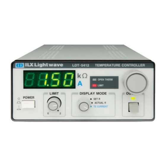
Page 12: Front Panel
Figure 2.1 5412 Front Panel AC Power-Up Sequence With the LDT-5412 connected to an AC power source, pressing the POWER off/on switch will supply power to the instrument and start the power-up sequence. DISPLAY MODE Selection The DISPLAY MODE select switch allows the user to select between the three display modes. -
Page 13: Main Control Knob
The OUTPUT off/on switch is located in the lower right-hand corner of the front panel. This switch has a toggling action which turns the output current of the LDT-5412 on and off. When the output is active, the LED indicator just above the switch will be lit. -
Page 14: Fault Indicators
OUTPUT is manually turned on again. • LIMIT - indicates that the LDT-5412 output is being limited to the setting of the front panel LIMIT knob. When a LIMIT condition occurs, the LIMIT indicator becomes lit. -
Page 15: Rear Panel
ACTUAL R, external set resistor connectors (located on J301) and SET RESISTOR switch, GAIN control, power cord receptacle, and serial number sticker. Figure 2.2 LDT-5412 Rear Panel Note: A solid line indicates that the pins are internally jumpered. Figure 2.3 D-connector (J301) Pinout... -
Page 16: Output Connectors
The Control Signal is available at pin 10 of J301. This provides (approximately) a 1 V/A signal which can be used to drive booster current supplies. Grounding Considerations The outputs of the LDT-5412 are isolated from chassis ground, allowing either output terminal to be grounded at the user's option. THERMISTOR CURRENT Switch The thermistor source current set switch selects the thermistor current supply of either 10 uA or 100 uA. -
Page 17: Gain Control
°C. Storage temperatures should be in the range of -40 to 70 °C. In order to achieve rated accuracy, the LDT-5412 should be warmed up for 1 hour before use. Note: To prevent overheating, the LDT-5412 must be kept well ventilated. Allow at least 1/2 inch clearance around the vent holes. 05_11 LDT-5412 ... -
Page 18: Operating Instructions
Operating Instructions Operating Instructions The following sections contain instructions on the set-up and operation of the LDT-5412. Connecting to Your Device When connecting or disconnecting laser diode modules and other sensitive devices to your 5412, we recommend that the OUTPUT be turned off (LED unlit). -
Page 19: Temperature From Resistance
In these tables the resistance is not given directly. But rather, a scaling factor is given at each temperature. Resistance is found then by multiplying the nominal resistance value 05_11 LDT-5412 ... -
Page 20: Use Of The Steinhart-Hart Equation
Generally, the Steinhart-Hart constants for a thermistor are not specified by the thermistor manufacturer. These constants may be derived specifically for each thermistor, or the nominal value for a thermistor may be used (see Appendix A). ILX Lightwave supplies the S-H constants when a TS-510 calibrated thermistor is purchased. ... -
Page 21: Calibrated Thermistors
When the ANALOG OUTPUT signal is connected to a calculator or meter with external control signal capability and memory to store a conversion formula (such as the Steinhart-Hart equation), the resistance can be converted to temperature directly. 05_11 LDT-5412 ... -
Page 22: Sensing Current And Thermistor Selection
Thermistor resistance and voltage are related through Ohms Law (V = I x R). The LDT-5412 supplies current to the thermistor, either 10 uA or 100 uA, and as the resistance changes a changing voltage signal is available to the thermistor inputs of the 5412. -
Page 23: Selecting And Using Thermistors
DEGREES C 10 A 100 A - Denotes practical range with typical 10K thermistor - Denotes measurable range with typical 10K thermisto * ILX default values for C1 and C2 Figure 2.5 Thermistor Temperature Range 05_11 LDT-5412 ... - Page 24 O P E R A T I O N C H A P T E R Sensing Current and Thermistor Selection LDT-5412...
-
Page 25: Maintenance And Troubleshooting
Consult the factory for service instructions. Troubleshooting This appendix is a guide to troubleshooting the LDT-5412. Some of the more common symptoms are listed here, and the appropriate troubleshooting actions are given. We recommend that the user start at the beginning of this guide. Read the symptom descriptions, and follow the steps for the corrective actions which apply. - Page 26 • Check the AC line cord to make sure that it is well-connected. TE module won't heat or cool. • Check the LIMIT control. If the current is too low, the desired temperature (resistance) may never be attained. LDT-5412...
-
Page 27: Appendix A Use Of The Steinhart-Hart Equation
+5oC. The following program can be used to simultaneously solve the three equations to determine the constants C1, C2, and C3. Some nominal values for the Steinhart-Hart constants for various thermistors are presented at the end of this appendix. LDT-5412 ... -
Page 28: Determining The Steinhart-Hart Constants
RandT.BAS program below. For more information on using the S-H equation, refer to ILX Lightwave Application Note #4. Using the S-H Equation to Find Resistance or Temperature ... - Page 29 'find temperature given resistance 300 T! = (1! / (C1! + C2! * LOG(R!) + C3! * (LOG(R!)^3))) - 273.15 310 PRINT " Temperature in C = "; T! : PRINT : GOTO 140 320 ' 330 END 05_11 LDT-5412 ...
-
Page 30: Steinhart-Hart Constants
General Optronics Modules 1.126 2.346 0.861 The nominal S-H constant values listed above were determined from the manufacturer's raw data, assuming 0% resistance tolerance. The better the tolerance of your thermistor, the better the accuracy when using these nominal values. LDT-5412...
Need help?
Do you have a question about the LDT-5412 and is the answer not in the manual?
Questions and answers