WAGO I/OSYSTEM 750 Series Manual
Fieldbus independent i/o modules, incremental encoder interfaces
Hide thumbs
Also See for I/OSYSTEM 750 Series:

Related Manuals for WAGO I/OSYSTEM 750 Series


Summary of Contents for WAGO I/OSYSTEM 750 Series
- Page 1 Fieldbus Independent I/O Modules Incremental Encoder Interfaces 750-637, (/xxx-xxx) Manual Version 1.4.0...
- Page 2 • General Copyright 2008 by WAGO Kontakttechnik GmbH & Co. KG All rights reserved. WAGO Kontakttechnik GmbH & Co. KG Hansastraße 27 D-32423 Minden Phone: +49 (0) 571/8 87 – 0 Fax: +49 (0) 571/8 87 – 1 69 E-Mail: info@wago.com...
-
Page 3: Table Of Contents
Schematic Diagram............... 35 2.1.4.5 Technical Data ................36 2.1.4.6 Functional Description..............38 2.1.4.7 Process Image ................39 2.1.5 750-637/000-004 [Inc.Enc./24V/32Bit/S.E./cam] ......43 2.1.5.1 View....................43 2.1.5.2 Description..................43 2.1.5.3 Display Elements ................45 2.1.5.4 Schematic Diagram............... 45 WAGO-I/O-SYSTEM 750 I/O Modules... - Page 4 DEMKO 08 ATEX 142851X and IECEx PTB 07.0064)....60 3.2.2 Special conditions for safe use (ATEX Certificate TÜV 07 ATEX 554086 X) ..................61 3.2.3 Special conditions for safe use (IEC-Ex Certificate TUN 09.0001 X)62 3.2.4 ANSI/ISA 12.12.01 ................63 WAGO-I/O-SYSTEM 750 I/O Modules...
-
Page 5: Important Notes
Co. KG, Minden, Germany. Non-observance will involve the right to assert damage claims. WAGO Kontakttechnik GmbH & Co. KG reserves the right to provide for any alterations or modifications that serve to increase the efficiency of technical progress. WAGO Kontakttechnik GmbH & Co. KG owns all rights arising from the granting of patents or from the legal protection of utility patents. -
Page 6: Use Of The 750 Series In Compliance With Underlying Provisions
Legal Bases All responsible persons have to familiarize themselves with the underlying legal standards to be applied. WAGO Kontakttechnik GmbH & Co. KG does not assume any liability whatsoever resulting from improper handling and damage incurred to both WAGO´s own and third-party products by disregarding detailed information in this Manual. -
Page 7: Standards And Guidelines For Operating The 750 Series
(emissions of interference) in compliance with EN 61000-6-3. You will find the detailed information in section "WAGO-I/O-SYSTEM 750" "System Description" "Technical Data". Please observe the safety precautions against electrostatic discharge in accordance with DIN EN 61340-5-1/-3. -
Page 8: Symbols
Observe the precautionary measure for handling components at risk of electrostatic discharge. Note Make important notes that are to be complied with so that a trouble-free and efficient device operation can be guaranteed. Additional Information References to additional literature, manuals, data sheets and internet pages. WAGO-I/O-SYSTEM 750 I/O Modules... -
Page 9: Safety Information
Danger The WAGO-I/O-SYSTEM 750 and its components are an open system. It must only be assembled in housings, cabinets or in electrical operation rooms. Access is only permitted via a key or tool to authorized qualified personnel. -
Page 10: Font Conventions
1.7 Scope This manual describes the special modules 750-637, (/xxx-xxx) Incremental Encoder Interfaces of the modular WAGO-I/O-SYSTEM 750. Handling, assembly and start-up are described in the manual of the Fieldbus Coupler. Therefore this documentation is valid only in the connection with the... -
Page 11: O Modules
Sensor Operation DC 5 V DC 24 V DC 24 V DC 5 V DC 5 V Voltage Interpretation fourfold fourfold fourfold single single Bit Width 32 Bit 32 Bit 32 Bit 32 Bit 32 Bit WAGO-I/O-SYSTEM 750 I/O Modules... -
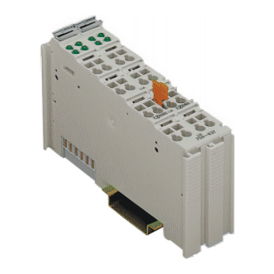
Page 12: 750-637 [Inc.enc./Rs422/32Bit/Diff.]
RS 422 connection. The data width of the encoder module is 32 bits. Either the current counter reading, the latch value, the set value or the current speed can be mapped into the process data. WAGO-I/O-SYSTEM 750 I/O Modules... - Page 13 The shield (screen) is directly connected to the carrier rail. The module 750-637 can be used with all couplers/controllers of the WAGO-I/O-SYSTEM 750 (except for the economy types 750-320, -323, -324 and -327). The version of both hardware and software that are valid for this module is specified in the manufacturing number, which is part of the lateral marking on the module.
-
Page 14: Display Elements
Output = 24 V 2.1.2.5 Schematic Diagram 24V/0V A B C _ _ _ A B C A,B,C N1/N2 N1/N2 Logic Latch Latch/Gate Gate/Ref Gate /Ref Latch Ref/Shield Shield Ve/V (screen) (screen) 750-637 Fig. 2.1.2-2: Schematic Diagram g063701e WAGO-I/O-SYSTEM 750 I/O Modules... -
Page 15: Technical Data
Output resistance 160 m typ. Digital Inputs (Latch, Gate, Ref) Input voltage (0) DC –3 V ... +5 V (1) DC +15 V ... +30 V Input current Latch: 5 mA typ. Gate and Ref: 7 mA WAGO-I/O-SYSTEM 750 I/O Modules... - Page 16 Class I Div2 ABCD T4 More Information Detailed references to the approvals are listed in the document "Overview Approvals WAGO-I/O-SYSTEM 750", which You can find on the CD ROM ELECTRONICC Tools and Docs (Item-No.: 0888-0412/…) or in the Internet under: http://www.wago.com...
- Page 17 750-637 [Inc.Enc./RS422/32Bit/Diff.] • 17 Technical Data Further „General Technical Data“ for the WAGO-I/O-SYSTEM 750 is available in the specific fieldbus coupler / controller manuals. WAGO-I/O-SYSTEM 750 I/O Modules...
-
Page 18: Functional Description
Ground for the 24 V supply voltage, internally connected with U Output Function N1, N2 Cam output, 24 V, 0.5 A "1" - Counter value is within of the defined range "0" - Counter value is outside of the defined range WAGO-I/O-SYSTEM 750 I/O Modules... -
Page 19: Process Image
The setting is mirrored in status byte S1 in bit 0 and bit 1. MapPZD (Control Byte C1 / Status Byte S1, Bit 0 and 1) Bit 1 Bit 0 Coding of the Process data Counter value Latch value Velocity (Increments per milliseconds) Set value WAGO-I/O-SYSTEM 750 I/O Modules... - Page 20 Cam window 1st bit is set, if: bottom comparative value N1 ≤ counter reading ≤ top comparative value N1 Cam window 2nd bit is set, if: bottom comparative value N2 ≤ counter reading ≤ top comparative value N2 reserved WAGO-I/O-SYSTEM 750 I/O Modules...
- Page 21 OpMode 0=Capture Mode The counter is latched by a trigger signal 1=Preload Mode The counter is latched by a trigger signal. Subsequently, the counter is loaded with the set value. reserved WAGO-I/O-SYSTEM 750 I/O Modules...
- Page 22 - The controls must release EN_LATC (C1.0) or EN_LAT_EXT (C1.1) with a positive edge - A positive edge is created at input REF - Subsequently, the next positive edge at input C or input Latch leads to a Capture or Preload event reserved WAGO-I/O-SYSTEM 750 I/O Modules...
-
Page 23: 750-637/000-001 [Inc.enc./24V/32Bit/Diff.]
“C” or “Latch” is positive. The speed (increments/ms) is automatically recorded and can be transmitted as an alternative to the latch value. WAGO-I/O-SYSTEM 750 I/O Modules... - Page 24 The shield (screen) is directly connected to the carrier rail. The module 750-637/000-001 can be used with all couplers/controllers of the WAGO-I/O-SYSTEM 750 (except for the economy types 750-320, -323, -324 and -327). This description is valid for the XXXX0301... hardware and software version.
-
Page 25: Display Elements
Output = 24 V Schematic Diagram 24V/0V A B C _ _ _ A B C A,B,C N1/N2 N1/N2 Logic Latch Latch/Gate Gate/Ref Gate /Ref Latch Ref/Shield Shield (screen) (screen) 750-637/000-001 Fig. 0-2: Schematic Diagram g063711e WAGO-I/O-SYSTEM 750 I/O Modules... -
Page 26: Technical Data
(1) DC +30 V > (U(B) - U(/B)) > DC +15 V Input voltage C, /C (0) DC -30 V < (U(C) - U(/C)) < DC -15 V (1) DC +30 V > (U(C) - U(/C)) > DC +15 V WAGO-I/O-SYSTEM 750 I/O Modules... - Page 27 More Information Detailed references to the approvals are listed in the document "Overview Approvals WAGO-I/O-SYSTEM 750", which You can find on the CD ROM ELECTRONICC Tools and Docs (Item-No.: 0888-0412/…) or in the Internet Service Downloads Documentation ...
-
Page 28: Functional Description
Ground for the 24 V supply voltage Output Function N1, N2 Cam output, 24 V, 0.5 A "1" - Counter value is within of the defined range "0" - Counter value is outside of the defined range WAGO-I/O-SYSTEM 750 I/O Modules... -
Page 29: Process Image
The setting is mirrored in status byte S1 in bit 0 and bit 1. MapPZD (Control Byte C1 / Status Byte S1, Bit 0 and 1) Bit 1 Bit 0 Coding of the Process data Counter value Latch value Velocity (Increments per milliseconds) Set value WAGO-I/O-SYSTEM 750 I/O Modules... - Page 30 Cam window 1st bit is set, if: bottom comparative value N1 <= Counter reading <= top comparative value N1 Cam window 2nd bit is set, if: bottom comparative value N2 <= Counter reading <= top comparative value N2 reserved WAGO-I/O-SYSTEM 750 I/O Modules...
- Page 31 OpMode 0=Capture Mode The counter is latched by a trigger signal 1=Preload Mode The counter is latched by a trigger signal. Subsequently, the counter is loaded with the set value. reserved WAGO-I/O-SYSTEM 750 I/O Modules...
- Page 32 - The controls must release EN_LATC (C1.0) or EN_LAT_EXT (C1.1) with a positive edge - A positive edge is created at input REF - Subsequently, the next positive edge at input C or input Latch leads to a Capture or Preload event reserved WAGO-I/O-SYSTEM 750 I/O Modules...
-
Page 33: 750-637/000-002 [Inc.enc./24V/32Bit/S.e.]
“C” or “Latch” is positive. The speed (increments/ms) is automatically recorded and can be transmitted as an alternative to the latch value. WAGO-I/O-SYSTEM 750 I/O Modules... - Page 34 The shield (screen) is directly connected to the carrier rail. The module 750-637/000-002 can be used with all couplers/controllers of the WAGO-I/O-SYSTEM 750 (except for the economy types 750-320, -323, -324 and -327). This description is valid for the XXXX0301... hardware and software version.
-
Page 35: Display Elements
Output = 0 V green Output = 24 V 2.1.3.4 Schematic Diagram 24V/0V A B C A,B,C N1/N2 N1/N2 Logic Latch Latch/Gate Gate/Ref Gate /Ref Latch Ref/Shield Shield (screen) (screen) 750-637/000-002 Fig. 2.1.3-2: Schematic Diagram g063721e WAGO-I/O-SYSTEM 750 I/O Modules... -
Page 36: Technical Data
(0) DC 0 V < U(B) < DC 5 V (1) DC 30 V > U(B) > DC 15 V Input voltage C, /C (0) DC 0 V < U(C) < DC 5 V (1) DC 30 V > U(B) > DC 15 V WAGO-I/O-SYSTEM 750 I/O Modules... - Page 37 Class I Div2 ABCD T4A More Information Detailed references to the approvals are listed in the document "Overview Approvals WAGO-I/O-SYSTEM 750", which You can find on the CD ROM ELECTRONICC Tools and Docs (Item-No.: 0888-0412/…) or in the Internet under: http://www.wago.com...
-
Page 38: Functional Description
Ground for the 24 V supply voltage Output Function N1, N2 Cam output, 24 V, 0.5 A "1" - Counter value is within of the defined range "0" - Counter value is outside of the defined range WAGO-I/O-SYSTEM 750 I/O Modules... -
Page 39: Process Image
The setting is mirrored in status byte S1 in bit 0 and bit 1. MapPZD (Control Byte C1 / Status Byte S1, Bit 0 and 1) Bit 1 Bit 0 Coding of the Process data Counter value Latch value Velocity (Increments per milliseconds) Set value WAGO-I/O-SYSTEM 750 I/O Modules... - Page 40 Cam window 1st bit is set, if: bottom comparative value N1 <= Counter reading <= top comparative value N1 Cam window 2nd bit is set, if: bottom comparative value N2 <= Counter reading <= top comparative value N2 reserved WAGO-I/O-SYSTEM 750 I/O Modules...
- Page 41 OpMode 0=Capture Mode The counter is latched by a trigger signal 1=Preload Mode The counter is latched by a trigger signal. Subsequently, the counter is loaded with the set value. reserved WAGO-I/O-SYSTEM 750 I/O Modules...
- Page 42 - The controls must release EN_LATC (C1.0) or EN_LAT_EXT (C1.1) with a positive edge - A positive edge is created at input REF - Subsequently, the next positive edge at input C or input Latch leads to a Capture or Preload event reserved WAGO-I/O-SYSTEM 750 I/O Modules...
-
Page 43: 750-637/000-004 [Inc.enc./24V/32Bit/S.e./Cam]
“C” or “Latch” is positive. The speed (increments/ms) is automatically recorded and can be transmitted as an alternative to the latch value. WAGO-I/O-SYSTEM 750 I/O Modules... - Page 44 The shield (screen) is directly connected to the carrier rail. The module 750-637/000-002 can be used with all couplers/controllers of the WAGO-I/O-SYSTEM 750 (except for the economy types 750-320, -323, -324 and -327). This description is valid for the XXXX0101... hardware and software version.
-
Page 45: Display Elements
Output = 0 V green Output = 24 V 2.1.4.4 Schematic Diagram 24V/0V A B C A,B,C N1/N2 N1/N2 Logic Latch Latch/Gate Gate/Ref Gate /Ref Latch Ref/Shield Shield (screen) (screen) 750-637/000-004 Fig. 2.1.4-2: Schematic Diagram g063741e WAGO-I/O-SYSTEM 750 I/O Modules... -
Page 46: Technical Data
Output resistance 160 m typ. Digital Inputs (Latch, Gate, Ref) Input voltage (0) DC –3 V ... +5 V (1) DC +15 V ... +30 V Input current Latch: 5 mA typ. Gate and Ref: 7 mA WAGO-I/O-SYSTEM 750 I/O Modules... -
Page 47: Functional Description
Class I Div2 ABCD T4 More Information Detailed references to the approvals are listed in the document "Overview Approvals WAGO-I/O-SYSTEM 750", which You can find on the CD ROM ELECTRONICC Tools and Docs (Item-No.: 0888-0412/…) or in the Internet under: http://www.wago.com... - Page 48 When the voltage is restored, all cams remain reset independent of the previous switching state (output voltage 0 V). The voltage failure is reported to the control unit via a status bit. The cam windows must then be set anew. WAGO-I/O-SYSTEM 750 I/O Modules...
-
Page 49: Process Image
Latch value The setting is mirrored in status byte S1 in bit 0 and bit 1. MapPZD (Control Byte C1 / Status Byte S1, Bit 0) Bit 0 Coding of the Process data Counter value Latch value WAGO-I/O-SYSTEM 750 I/O Modules... - Page 50 Bit = 1 The field voltage is < 5 V Bit = 0 The field voltage is > 20.4 V After a power failure, all cam windows are set to 0. The counter reading is set to 0. reserved WAGO-I/O-SYSTEM 750 I/O Modules...
- Page 51 The bit is set if bottom comparison value N2F1_LO < counter reading < upper comparison value N2F1_HI and the cams are enabled ( C1.6 ), and the field voltage is available ( S0.6 = 0). Reserved (These bits should be masked in the PLC) WAGO-I/O-SYSTEM 750 I/O Modules...
- Page 52 Bit = 0 Capture Mode The counter is latched by a trigger signal Bit = 1 Preload Mode The counter is latched by a trigger signal. Subsequently, the counter is loaded with the set value. reserved WAGO-I/O-SYSTEM 750 I/O Modules...
- Page 53 Bit = 0 All cam outputs are disabled; i.e., output voltage 0 V Bit = 1 All cam outputs are enabled; i.e., output voltage 24 V _Nocken The request is acknowledged in status bit Enable_Cams (S0.3). reserved WAGO-I/O-SYSTEM 750 I/O Modules...
-
Page 54: Use In Hazardous Environments
10BSpecial Modules Use in Hazardous Environments The WAGO-I/O-SYSTEM 750 (electrical equipment) is designed for use in Zone 2 hazardous areas. The following sections include both the general identification of components (devices) and the installation regulations to be observed. The individual subsections of the "Installation Regulations"... -
Page 55: Identification
DEMKO 08 ATEX 142851 X Approval body and/or number of the examination IECEx PTB 07.0064X certificate I M2 / II 3 GD Device group and Unit category Ex nA Type of ignition and extended identification Device group Temperature class WAGO-I/O-SYSTEM 750 I/O Modules... - Page 56 56 • Use in Hazardous Environments Identification Figure 1: Example of side marking of Ex i and IEC Ex i approved I/O modules Figure 2: Inscription text detail acc. CENELEC and IEC WAGO-I/O-SYSTEM 750 I/O Modules...
- Page 57 Device category: Zone 2 device (Zone 0 subunit) Explosion protection mark Type of protection: Non-sparking operating equipment [ia] Category of type of protection intrinsic safety: Even safe when two errors occur Explosion Group Temperature class: Max. surface temperature 135°C WAGO-I/O-SYSTEM 750 I/O Modules...
-
Page 58: For America According To Nec 500
Tab. 0-2: Description of Printing on Printing on Text Description CL 1 Explosion protection group (condition of use category) DIV 2 Area of application (zone) Grp. ABCD Explosion group (gas group) Op temp. code T4 Temperature class WAGO-I/O-SYSTEM 750 I/O Modules... -
Page 59: Installation Regulations
Installation Regulations NFPA 70 National Electrical Code Art. 500 Hazardous Locations ANSI/ISA-RP 12.6-1987 Recommended Practice C22.1 Canadian Electrical Code Warning When using the WAGO-I/O SYSTEM 750 (electrical operation) with Ex approval, the following points are mandatory: WAGO-I/O-SYSTEM 750 I/O Modules... -
Page 60: Special Conditions For Safe Operation Of The Atex And Iec Ex (Acc. Demko 08 Atex 142851X And Iecex Ptb 07.0064)
2.3.1 Special Conditions for Safe Operation of the ATEX and IEC Ex (acc. DEMKO 08 ATEX 142851X and IECEx PTB 07.0064) The fieldbus-independent I/O modules of the WAGO-I/O-SYSTEMs 750-.../...-... Must be installed in an environment with degree of pollution 2 or better. In the final... -
Page 61: Special Conditions For Safe Use (Atex Certificate Tüv 07 Atex 554086 X)
554086 X) For use as Gc- or Dc-apparatus (in zone 2 or 22) the fieldbus independent I/O modules WAGO-I/O-SYSTEM 750-*** shall be erected in an enclosure that fulfils the requirements of the applicable standards (see the marking) EN 60079-0, EN 60079-11, EN 60079-15, EN 61241-0 and EN 61241-1. - Page 62 2.3.3 Special conditions for safe use (IEC-Ex Certificate TUN 09.0001 For use as Dc- or Gc-apparatus (in zone 2 or 22) the fieldbus independent I/O modules WAGO-I/O-SYSTEM 750-*** shall be erected in an enclosure that fulfils the requirements of the applicable standards (see the marking) IEC 60079-0, IEC 60079-11, IEC 60079-15, IEC 61241-0 and IEC 61241-1.
-
Page 63: Ansi/Isa 12.12.01
The switch need not be integrated in the equipment. For devices with Ethernet connectors: ”Only for use in LAN, not for connection to telecommunication circuits.” Warning Use Module 750-642 only with antenna module 758-910. WAGO-I/O-SYSTEM 750 I/O Modules... - Page 64 WAGO Kontakttechnik GmbH & Co. KG Postfach 2880 • D-32385 Minden Hansastraße 27 • D-32423 Minden Phone: 05 71/8 87 – 0 Fax: 05 71/8 87 – 1 69 E-Mail: info@wago.com Internet: http://www.wago.com...
Need help?
Do you have a question about the I/OSYSTEM 750 Series and is the answer not in the manual?
Questions and answers