Table of Contents
Advertisement
Advertisement
Table of Contents

Related Manuals for Ross Ultricore RCP-ME


Summary of Contents for Ross Ultricore RCP-ME
- Page 1 RCP-ME User Guide...
- Page 2 Ross has become well known for the Ross Video Code of Ethics. It guides our interactions and empowers our employees. I hope you enjoy reading it below. If anything at all with your Ross experience does not live up to your expectations be sure to reach out to us at solutions@rossvideo.com.
- Page 3 Copyright ©2017 Ross Video Limited, Ross®, and any related marks are trademarks or registered trademarks of Ross Video Limited. All other trademarks are the property of their respective companies. PATENTS ISSUED and PENDING. All rights reserved. No part of this publication may be reproduced, stored in a retrieval system, or transmitted in any form or by any means, mechanical, photocopying, recording or otherwise, without the prior written permission of Ross Video.
- Page 4 If an item becomes defective within the warranty period Ross will repair or replace the defective item, as determined solely by Ross. Warranty repairs will be conducted at Ross, with all shipping FOB Ross dock. If repairs are conducted at the customer site, reasonable out-of-pocket charges will apply.
- Page 5 To avoid the potential release of those substances into the environment and to diminish the need for the extraction of natural resources, Ross Video encourages you to use the appropriate take-back systems. These systems will reuse or recycle most of the materials from your end-of-life equipment in an environmentally friendly and health conscious manner.
-
Page 7: Table Of Contents
Contents Introduction Related Publications..............................11 Documentation Conventions........................... 12 Contacting Technical Support..........................12 Hardware Overview Front Panel Overview ............................. 15 Rear Panel Overview .............................. 16 Getting Started Features ................................... 17 Typical System Equipment ............................. 17 System Overview ..............................18 How the RCP-ME and Routing Switchers Communicate ..................18 Installation and Configuration Overview........................ - Page 8 Functions What is a Function?..............................45 Assigning Functions to Buttons on the RCP-ME....................46 Assigning a Protect Button............................47 Assigning a Take Button ............................47 Assigning a Chop Button ............................48 Assigning a Shift Button ............................48 Assigning a Panel Lock Button ..........................49 Clearing a Function from a Button..........................50 Macros What is a macro? ..............................51 Assigning a Macro Button............................51...
- Page 9 Managing Panel Configurations Saving the Current Configuration for the RCP-ME ....................73 Editing a Configuration File ........................... 74 Sending a Configuration File to a Device....................... 74 Loading the Factory Defaults Using DashBoard ....................75 Monitoring Adjusting the Contrast for the LCD........................77 Viewing Status and Alarms in DashBoard ......................
- Page 10 iv • Contents RCP-ME User Guide (v4.0)
-
Page 11: Introduction
Introduction This guide is for installers and operators of the Ross Video RCP-ME. It provides instructions on how to connect the panel to your routing switcher system, how to set up a configuration file for the RCP-ME, and how to operate the RCP-ME. -
Page 12: Documentation Conventions
Contact your IT department before connecting to your facility network to ensure that there are no conflicts. Contacting Technical Support At Ross Video, we take pride in the quality of our products, but if problems occur, help is as close as the nearest telephone. - Page 13 a voice message can be left and the call will be returned shortly. This team of highly trained staff is available to react to any problem and to do whatever is necessary to ensure customer satisfaction. • Technical Support: (+1) 613-652-4886 •...
- Page 14 14 • Introduction RCP-ME User Guide (v4.0)
-
Page 15: Hardware Overview
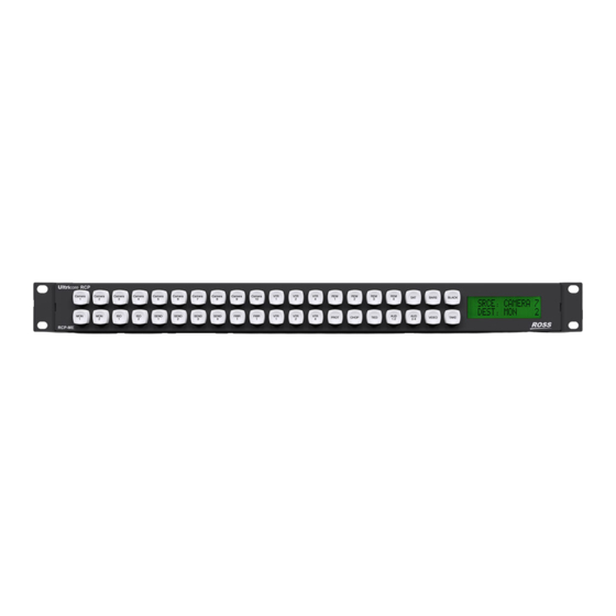
Hardware Overview The RCP-ME provides flexible connectivity of additional remote control panels and multi-page menu programming. Front Panel Overview This section provides a general overview of the RCP-ME front panel features. RCP-ME SRC: Server 1 1 2 3 4 DST: VTR 2 Figure 1.1 Front Panel of an RCP-ME 1. -
Page 16: Rear Panel Overview
1 2 3 4 00000002 ** MACRO PLAY ** 1 2 3 4 Figure 1.4 Examples of a Message Screen Error Screen An error screen appears briefly when the routing switcher sends a response back to the RCP-ME indicating that it cannot complete the request. -
Page 17: Getting Started
Getting Started Thank you for purchasing a Ross Video RCP-ME Remote Control Panel. This remote control panel enables you to control a routing switcher system from one point. With Ross Video’s reputation for delivering leading-edge routing switcher equipment and our unsurpassed level of customer service and support, you can look forward to many years of reliable broadcasting. -
Page 18: System Overview
System Overview A routing switcher system may use distributed control across the internet, a LAN, or a VPN. The routing switcher system shown in Figure 2.1 has been simplified. Server 1 Camera 1 RCP-ME Remote Control Panel ETHERNET Server 3 Ultrix 64x64 3G/HD/SD SDI Router Ultrix-HDNBC-IO... -
Page 19: Installation And Configuration Overview
When the routing switcher system is powered up, the routing switcher restores its crosspoint status. The RCP-ME requests the status of the routing switcher. The routing switcher sends the status of the crosspoints to the RCP-ME. Installation and Configuration Overview The generalized workflow of setting up your RCP-ME is: Implement your routing system plan. -
Page 20: Physical Installation
If anything is missing or damaged, contact your Ross Video office immediately to obtain the correct warranty service procedures. This ensures prompt assistance, minimal turnaround time, and avoids any freight issues. -
Page 21: Basic Configuration
Connecting to a Routing System The RCP-ME is designed for installation into a standard 19” equipment rack. It has integrated rack ears, allowing it to be screwed in using standard screws and cage nuts. To connect the remote control panel in the routing system Place the RCP-ME into the rack frame and then fix in place with appropriate fasteners. - Page 22 Accessing the RCP-ME Connection Editor The RCP-ME Connection Editor takes the panel’s configured name and sets the connections to the routing system. For More Information on... • the RCP-ME Connection Editor menus, refer to the section “RCP-ME Connection Editor Fields” on page 81. To open the RCP-ME Connection Editor Launch DashBoard.
-
Page 23: Adding The Rcp-Me To The Dashboard Tree View
The Panel Config interface opens. Adding the RCP-ME to the DashBoard Tree View In order to access the RCP-ME in DashBoard and configure its settings, the RCP-ME needs to be detected and the IP address for the LAN configured for use within a network using Walkabout. Once the network settings are configured in Walkabout, the RCP-ME is visible in DashBoard and you can update the panel device details, button assignments, and a configuration file sent to it. - Page 24 • Netmask – double-click inside the cell to enter an IP netmask for the RCP-ME. The default is 255.255.255.0. • Gateway – double-click inside the cell to enter an IP gateway for the RCP-ME. The default is 192.168.20.1. Refresh the Basic Tree View. The RCP-ME is added to the devices listed in the Basic Tree View.
- Page 25 Connecting to the Routing System Once you have established communication between the DashBoard client and the RCP-ME, you will need to connect the panel to the routing system. You can specify multiple devices for the RCP-ME to communicate with, but the panel will only connect to one device at a time (as indicated by the read-only Connected check box beside the IP Address for the device).
-
Page 26: Setting Up The Routing Mode
Setting up the Routing Mode The RCP-ME can be configured for one of two routing modes: • Physical mode — the input (or output) label 1 refers to input socket #1 on the rear of a physical router. Input label #2 refers directly to input socket #2 and so on. The label number or row, maps directly to the input or output physical connection number of a router. -
Page 27: Resetting Devices
To-deassign a resource Select the destination to which the resource is attached. Press DE-ASIGN. If the selected destination does not include a resource, one of two things will occur: • If the panel is in MC mode, park the current destination (switch same source number to destination). •... - Page 28 28 • Getting Started RCP-ME User Guide (v4.0)
-
Page 29: Destination And Sources
Destination and Sources Destination and source buttons map the physical connections on the routing switcher to the RCP-ME. You can provide labels for these physical connections using the Input Assigns and Output Assigns tabs in the Panel Config interface for the RCP-ME. ... -
Page 30: Assigning A Destination Or Source Button
Press Enter The name of the item of destination/source equipment appears on the corresponding button on the simulated RCP-ME in DashBoard. Repeat step 1 to 5 until all of the outputs and inputs on the routing switchers have been assigned a label for the connected destination and source equipment. -
Page 31: Assigning A Crosspoint Button
Assigning a Source to a Button A source represents the device that sends the physical input to the routing switcher. A switch occurs when a source button is pressed and the signal is routed to the currently selected destination. The function of any source button on a menu is changed when a button is assigned to the menu (see TAKE “Assigning a Take Button”... -
Page 32: Setting The Retry Time For A Switch Failure
Setting the Retry Time for a Switch Failure When using an NK series router with an RCP-ME and you make a switch, a switch request is sent from the RCP-ME to the NK-NET (or NK-IPS) and forwarded to the NK routing switcher. If the RCP-ME does not receive a response from the routing switcher, the RCP-ME retries the request after the time specified in the Comms Retry Delay Factor field. -
Page 33: Toggling Between Two Sources
Press the source button that you want to use. In the example below, is the selected source. RCP-ME VTR1 VTR2 VTR3 VTR4 TAKE SRC: HD 1 1 2 3 4 DST: EDIT 3 EDIT EDIT EDIT SAT1 SAT2 SAT3 If a button is assigned to the menu, the text on the screen that identifies the source button alternates TAKE between Take ? and the selected source label. - Page 34 SRC: Server 1 1 2 3 4 DST: VTR 2 SRC: Camera 1 1 2 3 4 DST: VTR 2 Figure 3.1 Toggling between two sources using slow chop • Press twice to toggle rapidly between the two sources (toggle cadence is 400 ms). The source label on CHOP the screen toggles between the two sources.
-
Page 35: Breakaways And Levels
Breakaways and Levels Routing systems often compromise many different signal types, and these may be in separate physical units. To control these units collectively or independently, we assign a level so the control system may differentiate between them. • A level is a single level (or layer) often comprising of a single signal type •... -
Page 36: Automatically Resetting A Custom Breakaway To The Default Breakaway After A Switch
Clear the remaining level masks from unused breakaways in the Breakaways table. In the Configuration section, use the Breakaway Warning Mode list to select the breakaway with which you want to compare the status of the router levels in the current breakaway. 10. -
Page 37: Assigning A Breakaway Step Button
Close the Button configuration box. The simulated RCP-ME in DashBoard shows the name of the breakaway on the selected button. For example, Tied. Send the current configuration file to the device (see “To send the current configuration to a panel” on page 74). -
Page 38: Assigning A Level Button
Assigning a Level Button A level button enables you to select one router level per button for a switch. While a breakaway is similar, breakaways can contain more than one router level. Multiple level buttons can be assigned on a panel. To assign a level to a button Open the RCP-ME Panel Config interface (see “To open the RCP-ME Panel Config interface”... -
Page 39: Viewing The Breakaways Assigned To An Rcp-Me
Viewing the Breakaways Assigned to an RCP-ME You can view the breakaways assigned to an RCP-ME if a breakaway step button is assigned to the RCP-ME. The breakaway step button cycles to the next breakaway in the list each time it is pressed. As each breakaway is selected, the level(s) defined in that breakaway are illuminated if corresponding level buttons have been assigned to the RCP-ME. - Page 40 Send the current configuration file to the device (see “To send the current configuration to a panel” on page 74). Using a Level Mask Button A Level Mask button enables you to quickly view what levels are selected, and edit which levels are included in the next crosspoint switch.
-
Page 41: Menus
Menus Menus can be used to group together certain functionality within the RCP-ME system. Each menu page provides a new set of 40 buttons that you can assign with new functions. What is a Menu button? A specific menu destination assigned to a button. You can set the button to return to Menu Number 1 (Home), the next or previously visited menu, or go up or down a menu as defined on the Menu Details tab in the Panel Config interface. -
Page 42: Assigning A Menu Link Button
› Fallback Off — After a button in the menu is pressed, the RCP-ME remains on the menu. If you select Fallback Off, the corresponding value in the Fallback Menu column is ignored. You must provide extra menu navigation buttons within the menu so that you can exit from the menu. ›... -
Page 43: Returning To The Home Menu
To assign menu navigation to a button Open the RCP-ME Panel Config interface (see “To open the RCP-ME Panel Config interface” on page 22). On the simulated RCP-ME, select the button that you want to use for menu navigation. The Button dialog opens. In the Button list, select Menu Navigate. - Page 44 Examples To select SRC HD1 to DEST VTR3 Select the destination by pressing VTR OUT EDIT SHIFT Press EDIT SHIFT Select the source by pressing EDIT SHIFT Press EDIT SHIFT To select SRC VTR2 to DEST SAT2 Select the destination by pressing EDIT SHIFT Press...
-
Page 45: Functions
Functions This chapter briefly summarizes how to assign a function to one of the buttons on the hard panel. What is a Function? The RCP-ME has some special function tasks that can be assigned to any button on the panel. The available functions are detailed below. -
Page 46: Assigning Functions To Buttons On The Rcp-Me
For example, a single button is assigned to Source 1, Source 21, or Source 31 depending on whether a button Shift is engaged: • Pressing accesses Source 1. SRC 1 • Pressing accesses SRC 21. SRC SH1 SRC 1 • Pressing accesses SRC 31. -
Page 47: Assigning A Protect Button
Close the Button dialog. The simulated RCP-ME in DashBoard shows the type of shift and shift page on the selected button. For example, SRC SH2. Send the current configuration file to the device (see “To send the current configuration to a panel” on page 74). -
Page 48: Assigning A Chop Button
To assign a take button Open the RCP-ME Panel Config interface (see “To open the RCP-ME Panel Config interface” on page 22). On the simulated RCP-ME, select the button that you want to use for the take button. The Button dialog opens. In the Button list, select Function Key. -
Page 49: Assigning A Panel Lock Button
• Shift 2 In the Value field, select an output or input assignment for the shift. Close the Button dialog. The simulated RCP-ME in DashBoard shows the type of shift and shift page on the selected button. For example, SRC SH2. Send the current configuration file to the device (see “To send the current configuration to a panel”... -
Page 50: Clearing A Function From A Button
In the Button list, select Function Key. In the Value field, select Panel Lock as the function to assign to this button. Close the Button dialog. The simulated RCP-ME in DashBoard shows the lock on the selected button. Clearing a Function from a Button If a button is not used for any function it should be unassigned. -
Page 51: Macros
Macros This chapter provides instructions for creating and editing macros, assigning a macro to a button, and using macros via the hard panel. What is a macro? A macro is a sequence of events (e.g. switches) that are assigned to a button. If you want to perform several tasks with the press of a single button, assign a macro button to the RCP-ME and then record a macro using this button. -
Page 52: Editing A Macro Using The Panel
Editing a Macro using the Panel You can add extra button sequences to an existing macro or you can join two existing macros together. To add to a macro using the panel On the RCP-ME, hold the Macro #x button until the button begins to flash rapidly. Release the button. -
Page 53: Using A Macro
Each function can occur on any available level, independent of any other function within the same macro event. 10. Repeat Steps 6 to 9 for any remaining events of the macro. 11. Send the current configuration file to the device (see “To send the current configuration to a panel” on page 74). - Page 54 54 • Macros RCP-ME User Guide (v4.0)
-
Page 55: Salvos
Salvos This chapter provides instructions for assigning a salvo to a button and how the RCP-ME uses salvos. What is a salvo? A salvo is a predefined list of switch events. Salvos are stored within a central controlling device such as an Ultrix router or Ultricore Central Controller and may be accessed by any Remote Control Panel within the system. - Page 56 56 • Salvos RCP-ME User Guide (v4.0)
-
Page 57: Category Index Mode
Category Index Mode Category Index mode allows alpha-numeric extensions to labels to 'build up' the final label selection. For example, VTR 1 - 6 may be expressed as a VTR label with numerical extensions 1 through 6. Similarly, alpha extensions may be used, for example, VTR A - E for VTRs A through E. -
Page 58: Entering Category Index Mode
The possible categories and indexes would be: Categories Indexes CAM_ SAT_ EDIT_ a. The “_” characters represents a blank space. This indicates the category will filter resources with a space in the name (e.g. the CAM_ category will allow resources named CAM 1, CAM 2 but not CAM3). - Page 59 RCP-ME TAKE EXIT DEST EDIT /SEL 1 2 3 4 Press EDIT The available EDIT indexes are lit. RCP-ME TAKE EXIT DEST EDIT /SEL 1 2 3 4 Press RCP-ME TAKE EXIT DEST EDIT 1 2 3 4 /SEL Press TAKE/SEL The display reports on the second line of the display to indicate the current destination.
- Page 60 60 • Category Index Mode RCP-ME User Guide (v4.0)
-
Page 61: Protects And Locks
Protects and Locks This chapter defines when to use a protect and lock, configuring a Protect or Lock button, how to protect a destination, and how to clear protects held by a RCP-ME. The RCP-ME protect mode may be set either in Protect mode or Lock mode. -
Page 62: Locking An Rcp-Me
In the Configuration section, select the mode of protection that you want to use for the button. Use the Protect information in Table 10.1 as a guide. Table 10.1 Protect Mode Descriptions Protect Mode Description Block Other The protected destination and level(s) cannot be switched to another source Panels (Protect) by other remote control panels. -
Page 63: Protecting A Destination
In the Configuration section, select the Panel Locked check box. Send the current configuration file to the device (see “To send the current configuration to a panel” on page 74). The RCP-ME is locked. If a panel button is assigned, it can be pressed to unlock the RCP-ME. LOCK To lock the RCP-ME using a panel lock button •... -
Page 64: Clearing Protects Held By An Rcp-Me
If you are protecting a destination on a level for which a routing switcher does not respond, a protect breakaway error (*PROT BRKWY ERR*) occurs. To remove the protection from a destination Press the button for the protected destination. Press the button. -
Page 65: Machine Control
Machine Control When configuring the RCP-ME, you have the option to enable Machine Control, and to add a Machine Control button to the panel. What is Machine Control? Typically, the ports on a data router (such as the NK-M series routers) are bi-directional where there is both a transmit (input to output) and reciprocal receive connection that is made for each port. -
Page 66: Configuring A De-Assign Button
Configuring a De-assign Button De-assign will disconnect a reciprocal machine control path through a machine control router, parking sources to their respective destinations. Similarly, if using resource management, de-assigning will park the resource inputs and outputs and de-allocate the resource to be used in other routes. To assign a de-assign button Open the RCP-ME Panel Config interface (see “To open the RCP-ME Panel Config interface”... -
Page 67: Linking Remote Control Panels
Linking Remote Control Panels If your routing switcher system is extensive, control of the entire system may not be possible through just one remote control panel. If this is the case, additional remote control panels may be added. You can choose to operate the remote control panels individually, or you can link the remote control panels together so they operate as one larger remote control panel. -
Page 68: Operating Linked Remote Control Panels
Operating Linked Remote Control Panels You can link multiple RCP-MEs together, or link them with one or more RCP-ME, RCP-NKMs, or RCP-NKQs, or a combination thereof. The remote control panels must have Panel Link Addresses set, as outlined in the section “Linking Remote Control Panels”... - Page 69 Breakaways Breakaway numbers are not sent in the switch request, thus removing the need for identical breakaway definitions across linked remote control panels. As such, breakaway step is not available across linked remote control panels. You can view the breakaways within the same remote control panel, in line with unlinked behavior. Menus Menus and menu navigation keys are only effective on the remote control panel to which they are assigned.
- Page 70 70 • Linking Remote Control Panels RCP-ME User Guide (v4.0)
-
Page 71: Cutbus Mode
Cutbus Mode Cutbus is a configuration that creates a default switching panel that only affects assigned outputs on a particular router. The RCP-ME has three modes of cutbus operation: cutbus off, cutbus normal, or multi. Setting Up Cutbus Normal Mode The panel operates in either single cutbus mode or dual cutbus mode. - Page 72 72 • Cutbus Mode RCP-ME User Guide (v4.0)
-
Page 73: Managing Panel Configurations
Managing Panel Configurations The parameters that you have set up on the Panel Config interface for an RCP-ME are stored to a configuration file on your DashBoard client PC. A configuration file can be recalled and applied to other remote control panels communicating with your DashBoard client PC. -
Page 74: Editing A Configuration File
Click Editing a Configuration File Any saved configuration files can be accessed and opened via the File Navigator pane in the DashBoard window. You can also open a saved configuration file, make changes to it, save it, and then send it to a panel. To edit a saved configuration file In the File Navigator pane, navigate to the saved configuration file that you want to open. -
Page 75: Loading The Factory Defaults Using Dashboard
Loading the Factory Defaults Using DashBoard If you need to return the RCP-ME to a known configuration, you can use DashBoard to load the factory defaults. This defaults the RCP-ME panel configuration (Panel Config interface settings) only, and not the connection configuration (Connection Editor). - Page 76 76 • Managing Panel Configurations RCP-ME User Guide (v4.0)
-
Page 77: Monitoring
Monitoring This chapter provides information on the display options for the LCD, how to monitor the panel via DashBoard, general tips to troubleshoot common problems, and briefly summarizes the steps required to update the firmware on the hard panel Adjusting the Contrast for the LCD You can fine tune the display contrast of the LCD on the front panel. -
Page 78: Troubleshooting
Contact Ross Technical Support for the latest software file for the RCP-ME. Checking the Firmware Version Firmware may be updated easily using DashBoard. To check for the latest firmware versions, contact Ross Video Technical Support. 78 • Monitoring RCP-ME User Guide (v4.0) - Page 79 The Panel Config interface opens. The firmware version is shown in the Version field located at the top of the interface. Upgrading the Firmware Version Firmware upgrade files can be obtained by contacting Ross Video Technical Support. To upgrade the RCP-ME firmware Launch DashBoard.
- Page 80 80 • Monitoring RCP-ME User Guide (v4.0)
-
Page 81: Dashboard Interface Overview
DashBoard Interface Overview This chapter outlines the interfaces, menus, and parameters available in DashBoard for the RCP-ME. RCP-ME Connection Editor Fields The RCP-ME Connector Editor interface displays in DashBoard when you double-click the second sub-node listed in the RCP-ME tree. This interface enables users to establish the RCP-ME network settings, such as the IP Address and TCP Port, assign the panel to a router group, and specify a unique identifier for the panel to be used in the DashBoard interfaces. - Page 82 Table 16.1 Device Details Area Item Parameters Description Details <text> Assigned by the user to give an RCP-ME specific details. For example, a physical location or a brief description of its use. This field has a maximum of 16 characters and is used for description and identification only.
-
Page 83: Panel Config Interface
In the event that the RCP-ME is unable to connect to a server or loses connectivity, it will attempt to connect to the next server after 10 seconds. For each server that the RCP-ME fails to connect to, it will attempt to connect to the next available server until it arrives back at the original server to which it attempted to connect. - Page 84 Top Toolbar The Device Details area is located in the top-right corner of the RCP-ME Panel Configuration Editor. This area displays information that identifies the RCP-ME within your routing system. Table 16.4 briefly summarizes the fields displayed in this Device Details area. Table 16.4 Device Details Area Area Item...
- Page 85 3. Button < > Field Click the arrow buttons to select a button from the panel or use the list to select a specific button. The available button functions are listed in the Button configuration box. Click a button on the simulated panel to open the Button configuration box.
- Page 86 Table 16.5 Configuration Tab Area Item Parameters Description Breakaways The list number of the breakaway (read-only) Name <text> The name assigned for the breakaway. The names are user configurable level mask (1...32) 1-32 Click a router level to: • assign a level mask ( ) or •...
- Page 87 Specify a router level for machine control Virtual Routing Selected Enable virtual routing. Virtual routing requires an Enabled NK-VRC in an Ross NK series router system. Virtual routing must be enabled for the RCP-ME to function with an Ultrix router or Ultricore Central Controller. Cleared...
- Page 88 Table 16.5 Configuration Tab Area Item Parameters Description Alarms Protect No Protect Indicates that there is no crosspoint protect enabled (read-only) (Green) on the panel Protect(s) Indicates that a crosspoint protect is enabled on the (Yellow) panel Menu Details Tab The Menu Details tab enables you to specify: •...
- Page 89 Table 16.6 Menu Details Tab Item Parameters Description Fallback Mode Fallback Off After a button in the menu is pressed, the RCP-ME remains on the menu the panel is currently on First Menu After a button in the menu is pressed, the RCP-ME returns to Menu Number 1 Previous Menu After a button in the menu is pressed, the RCP-ME...
- Page 90 Table 16.7 Output/Input Assigns Tab Item Parameters Description Import Global Labels Imports global labels (a file create and managed by DashBoard) for the input/output labels Output/Input Range Specifies the range of outputs/inputs to view in the Output/Input Assigns. The Assigns tab will only display the ranges in blocks of 120 outputs/inputs at a time, with each block selectable in the list.
- Page 91 Table 16.8 Macro Events Tab Item Parameters Description Output Specifies the destination output Input Specifies the source input Level Mask (1...32) Specifies the level mask(s) for the device affected by the macro Clear Clear the level mask(s) Set the level mask(s) Salvo Names Tab ...
- Page 92 Destination/Source Label Access Tabs The Label Access tabs allow or deny a panel access to a label. Even if a button is assigned with a specific source or destination label, and if the label access is denied (the box is unchecked), then a “ ”...
- Page 93 Table 16.12 lists the tab check boxes available in the Send Configuration dialog. Table 16.12 Send Configuration — Pages List Page Description Select Pages Selecting this selects every tab, including the Function and Key button definitions to send to the device. Home The information contained in the Device Details frame and the Configuration tab.
- Page 94 94 • DashBoard Interface Overview RCP-ME User Guide (v4.0)
-
Page 95: Rcp-Me Hexadecimal To Router Level Conversion
RCP-ME Hexadecimal to Router Level Conversion The router level is represented by eight hexadecimal characters. For each hexadecimal character, read the corresponding binary representation across the table. For each ‘1’ that appears in the binary representation, drop down to the Level row to read the actual router level included in the mask. - Page 96 17–96 • RCP-ME Hexadecimal to Router Level Conversion RCP-ME User Guide (v4.0)
-
Page 97: Glossary
Source — a logical label representing an input or group of inputs to the routing system. T-Bus — the Ross Video proprietary routing communication method via a defined physical interface. Tied (Audio Follow Video) — the default breakaway name referring to all routing system levels. - Page 98 98 • Glossary RCP-ME User Guide (v4.0)
Need help?
Do you have a question about the Ultricore RCP-ME and is the answer not in the manual?
Questions and answers